door key Alfa Romeo 159 2006 Owner handbook (in English)
[x] Cancel search | Manufacturer: ALFA ROMEO, Model Year: 2006, Model line: 159, Model: Alfa Romeo 159 2006Pages: 299, PDF Size: 4.64 MB
Page 35 of 299
33
SAFETY
DEVICES
WARNING LIGHTS
AND MESSAGES
IN AN
EMERGENCY
CAR
MAINTENANCE
TECHNICAL
SPECIFICATIONS
INDEX
DASHBOARD
AND
CONTROLS
CORRECT USE
OF THE CAR
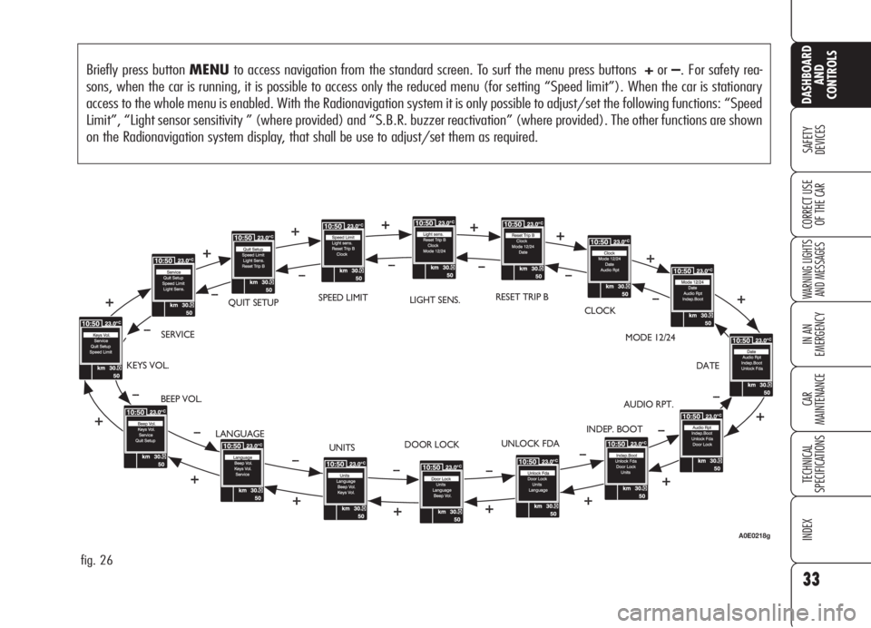
Briefly press button MENUto access navigation from the standard screen. To surf the menu press buttons +or–. For safety rea-
sons, when the car is running, it is possible to access only the reduced menu (for setting “Speed limit”). When the car is stationary
access to the whole menu is enabled. With the Radionavigation system it is only possible to adjust/set the following functions: “Speed
Limit”, “Light sensor sensitivity ” (where provided) and “S.B.R. buzzer reactivation” (where provided). The other functions are shown
on the Radionavigation system display, that shall be use to adjust/set them as required.
fig. 26
BEEP VOL.SERVICEQUIT SETUPLIGHT SENS.RESET TRIP B
CLOCK
MODE 12/24
DATE
AUDIO RPT.
INDEP. BOOT
UNLOCK FDA
DOOR LOCK
UNITS KEYS VOL.
LANGUAGESPEED LIMIT
A0E0218g
Page 39 of 299
37
SAFETY
DEVICES
WARNING LIGHTS
AND MESSAGES
IN AN
EMERGENCY
CAR
MAINTENANCE
TECHNICAL
SPECIFICATIONS
INDEX
DASHBOARD
AND
CONTROLS
CORRECT USE
OF THE CAR
Driver’s door unlocking
(Unlock Fda)
With this function it is possible to unlock
only the driver’s door by pressing the
electronic key button
Ë.
With this function active (ON), it is
however possible to unlock the other
doors by pressing the door unlock but-
ton on central console.
To activate/deactivate (ON/OFF) this
function proceed as follows:
❒briefly press button MENU:ONor
OFF(according to previous setting)
will flash on the display;
❒press button +or–to select the re-
quired language;
❒briefly press button MENUto go
back to the menu screen or press the
button for long to go back to the stan-
dard screen.Automatic central door locking
(Door lock)
When activated (ON), this function
locks automatically the doors when the
car speed exceeds 20 km/h.
To activate/deactivate (ON/OFF) this
function proceed as follows:
❒briefly press buttonMENU:ONor
OFF(according to previous setting)
will flash on the display;
❒press button +or–to select the re-
quired language;
❒briefly press button MENUto go
back to the menu screen or press the
button for long to go back to the stan-
dard screen.
Function activation is indicated by the
circular led around the button
q. Independent boot unlocking
(Indep. Boot)
With this function it is possible to unlock
the boot independently from doors.
When this function is on, to unlock the
boot press the electronic key button
`or use the lever set under the rear
left seat (see paragraph “Boot” in this
section).
To activate independent boot function
(ON) or deactivate it (OFF), proceed
as follows:
❒briefly press button MENU:ONor
OFF(according to previous setting)
will flash on the display;
❒press button +or–to select the re-
quired language;
❒briefly press button MENUto go
back to the menu screen or press the
button for long to go back to the stan-
dard screen.
Page 49 of 299
47
SAFETY
DEVICES
WARNING
LIGHTS AND
MESSAGES
IN AN
EMERGENCY
CAR
MAINTENANCE
TECHNICAL
SPECIFICATIONS
INDEX
CORRECT USE
OF THE CAR
DASHBOARD
AND
CONTROLS
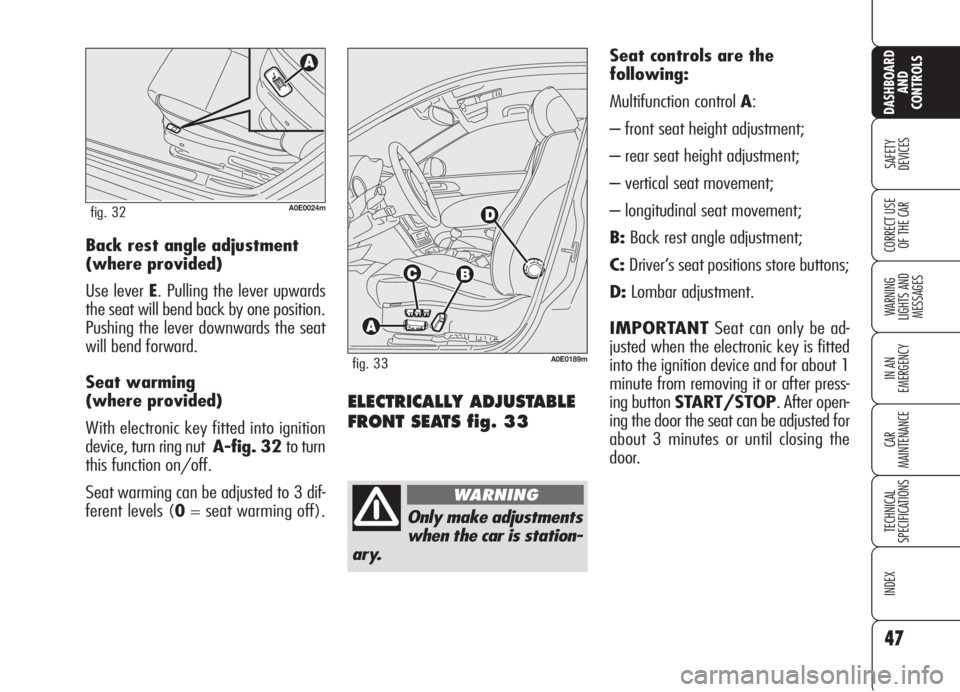
ELECTRICALLY ADJUSTABLE
FRONT SEATS fig. 33
Seat controls are the
following:
Multifunction control A:
– front seat height adjustment;
– rear seat height adjustment;
– vertical seat movement;
– longitudinal seat movement;
B:Back rest angle adjustment;
C:Driver’s seat positions store buttons;
D:Lombar adjustment.
IMPORTANTSeat can only be ad-
justed when the electronic key is fitted
into the ignition device and for about 1
minute from removing it or after press-
ing button START/STOP. After open-
ing the door the seat can be adjusted for
about 3 minutes or until closing the
door. Back rest angle adjustment
(where provided)
Use lever E. Pulling the lever upwards
the seat will bend back by one position.
Pushing the lever downwards the seat
will bend forward.
Seat warming
(where provided)
With electronic key fitted into ignition
device, turn ring nut A-fig. 32 to turn
this function on/off.
Seat warming can be adjusted to 3 dif-
ferent levels (0= seat warming off).
A0E0024mfig. 32
Only make adjustments
when the car is station-
ary.
WARNING
A0E0189mfig. 33
Page 50 of 299
48
SAFETY
DEVICES
WARNING
LIGHTS AND
MESSAGES
IN AN
EMERGENCY
CAR
MAINTENANCE
TECHNICAL
SPECIFICATIONS
INDEX
CORRECT USE
OF THE CAR
DASHBOARD
AND
CONTROLS
HEAD RESTRAINTS
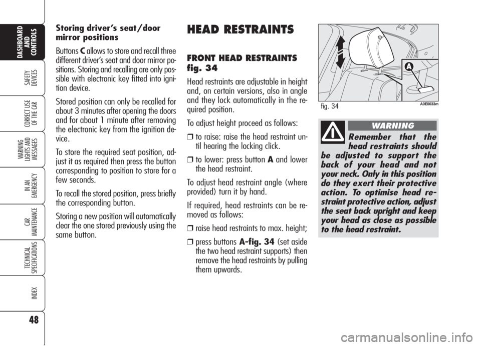
FRONT HEAD RESTRAINTS
fig. 34
Head restraints are adjustable in height
and, on certain versions, also in angle
and they lock automatically in the re-
quired position.
To adjust height proceed as follows:
❒to raise: raise the head restraint un-
til hearing the locking click.
❒to lower: press button Aand lower
the head restraint.
To adjust head restraint angle (where
provided) turn it by hand.
If required, head restraints can be re-
moved as follows:
❒raise head restraints to max. height;
❒press buttonsA-fig. 34(set aside
the two head restraint supports) then
remove the head restraints by pulling
them upwards. Storing driver’s seat/door
mirror positions
ButtonsCallows to store and recall three
different driver’s seat and door mirror po-
sitions. Storing and recalling are only pos-
sible with electronic key fitted into igni-
tion device.
Stored position can only be recalled for
about 3 minutes after opening the doors
and for about 1 minute after removing
the electronic key from the ignition de-
vice.
To store the required seat position, ad-
just it as required then press the button
corresponding to position to store for a
few seconds.
To recall the stored position, press briefly
the corresponding button.
Storing a new position will automatically
clear the one stored previously using the
same button.
A0E0033mfig. 34
Remember that the
head restraints should
be adjusted to support the
back of your head and not
your neck. Only in this position
do they exert their protective
action. To optimise head re-
straint protective action, adjust
the seat back upright and keep
your head as close as possible
to the head restraint.
WARNING
Page 53 of 299

51
SAFETY
DEVICES
WARNING
LIGHTS AND
MESSAGES
IN AN
EMERGENCY
CAR
MAINTENANCE
TECHNICAL
SPECIFICATIONS
INDEX
CORRECT USE
OF THE CAR
DASHBOARD
AND
CONTROLS
Electrically folding of the
mirror (only versions with 4
power windows)
When required (for example when the
mirror causes difficulty in narrow spaces)
it is possible to fold the mirrors by press-
ing button C-fig. 39.
To bring the mirrors back to driving po-
sition press again button C-fig. 39.
A0E0081mfig. 40
To adjust the mirror selected press but-
tonBin the four directions shown by
the arrows.
IMPORTANTAfter adjusting the mir-
ror, turn selector Ato0to prevent ac-
cidental movements.
Manually folding of the mirror
When required (for example when the
mirror causes difficulty in narrow spaces)
it is possible to fold the mirror moving it
from positionA-fig. 40 to position B.DOOR MIRRORS
Door mirror can only be adjusted and
folded when the electronic key is fitted
into the ignition device.
Adjusting the mirror
Use device A-fig. 39to select the re-
quired mirror:
❒turn selector Ato1to select the left
door mirror;
❒turn selector Ato2to select the right
door mirror.
A0E0036mfig. 39
As the driver’s door mir-
ror is curved, it may
slightly alter the per-
ception of distance.
When driving the mir-
rors shall always be in
open position.
WARNING
Page 54 of 299

52
SAFETY
DEVICES
WARNING
LIGHTS AND
MESSAGES
IN AN
EMERGENCY
CAR
MAINTENANCE
TECHNICAL
SPECIFICATIONS
INDEX
CORRECT USE
OF THE CAR
DASHBOARD
AND
CONTROLS
Storing the “parking”
position of the door mirror
on the passenger side
On versions equipped with electric seats,
when engaging reverse for parking to
improve visibility the driver can adjust
(and store) the passenger's door mirror
to a position different than that used
commonly. To store mirror position pro-
ceed as follows:
❒To perform storing, proceed as fol-
lows: engage reverse with car
stopped and electronic key fitted in-
to the ignition device;
❒move device A-fig. 39to position
2(passenger door mirror selection);
❒adjust the passenger door mirror to
obtain the best position for parking
manoeuvres;
❒keep one of the buttons C-fig. 33
pressed for at least 3 seconds (see
paragraph “Seats” in this section).
Together with the passenger door mir-
ror “parking” position, also the driver
seat position and the driver door mirror
will be stored. The sound of a buzzer
will confirm that the mirror position has
been stored.Recalling the passenger door
mirror “parking” position
Proceed as follows: fit the electronic key
into the ignition device, engage reverse,
move device A-fig. 39to position 2
(passenger door mirror selection).
The mirror will set automatically to the
previously stored position.
If no parking position has been stored,
when engaging reverse the passenger
door mirror will slightly lower to favour
the parking manoeuvre.
The passenger door mirror will return au-
tomatically to its original position about
10 seconds after disengaging reverse,
immediately after exceeding 10 km/h
with forward gear or when moving de-
viceA-fig. 39to0.Automatic door mirror
realignment
Each time the electronic key is fitted in-
to the ignition device the door mirrors
return automatically to the last position
reached and/or recalled before remov-
ing the electronic key from the ignition
device.
This enables mirror alignment if, when
the car is parked, one of the door mir-
rors has been moved manually and/or
accidentally.
Defrosting/demisting
The electric mirrors are fitted with heat-
ing coils which come into operation
when turning on the heated rear win-
dow (pressing button
().
IMPORTANTThis function is timed
and is deactivated after a few minutes.
Page 81 of 299
79
SAFETY
DEVICES
WARNING
LIGHTS AND
MESSAGES
IN AN
EMERGENCY
CAR
MAINTENANCE
TECHNICAL
SPECIFICATIONS
INDEX
CORRECT USE
OF THE CAR
DASHBOARD
AND
CONTROLS
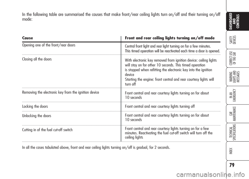
In the following table are summarised the causes that make front/rear ceiling lights turn on/off and their turning on/off
mode:
Cause
Opening one of the front/rear doors
Closing all the doors
Removing the electronic key from the ignition device
Locking the doors
Unlocking the doors
Cutting in of the fuel cut-off switch
Front and rear ceiling lights turning on/off mode
Central front light and rear light turning on for a few minutes.
This timed operation will be reactivated each time a door is opened.
With electronic key removed from ignition device: ceiling lights
will stay on for other 10 seconds. This timed operation
is stopped when refitting the electronic key into the ignition
device
Starting the engine: front central and rear courtesy lights will
turn off
Front central and rear courtesy lights turning on for about
10 seconds
Front central and rear courtesy lights turning off
Front central and rear courtesy lights turning on for about
10 seconds
Front central and rear courtesy lights turning on for a few
minutes. Reactivating the fuel cut-off switch will turn off the
ceiling lights
In all the cases tabulated above, front and rear ceiling lights turning on/off is gradual, for 2 seconds.
Page 82 of 299

DOOR PUDDLE LIGHTS
The door light will turn on when open-
ing the door regardless of the electron-
ic key position. It will stay on for about
3 minutes when the door is open, then
it will go off automatically.
80
SAFETY
DEVICES
WARNING
LIGHTS AND
MESSAGES
IN AN
EMERGENCY
CAR
MAINTENANCE
TECHNICAL
SPECIFICATIONS
INDEX
CORRECT USE
OF THE CAR
DASHBOARD
AND
CONTROLS
IMPORTANTLeaving inadvertently a
door open, the ceiling lights will turn off
automatically after a few minutes. To
turn them on again, open another door
or close and open again the same door.
Versions with sunroof
(where provided) fig. 60
Versions with sunroof are fitted with two
rear ceiling lights located above the rears
doors.
Press lens A-fig. 60to turn these
lights on/off.REAR CEILING LIGHT
Versions without sunroof
fig. 59
Press button:
A:to turn on/off the driver’s courtesy
light;
B:to turn on/off the passenger’s cour-
tesy light.
Closing the doors, the ceiling lights will
stay on for a few seconds, then they will
switch off automatically. Ceiling lights
will turn off when fitting the electronic
key into the ignition device.
A0E0094mfig. 59A0E0037mfig. 60
Page 83 of 299
81
SAFETY
DEVICES
WARNING
LIGHTS AND
MESSAGES
IN AN
EMERGENCY
CAR
MAINTENANCE
TECHNICAL
SPECIFICATIONS
INDEX
CORRECT USE
OF THE CAR
DASHBOARD
AND
CONTROLS
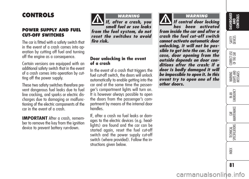
CONTROLS
POWER SUPPLY AND FUEL
CUT-OFF SWITCHES
The car is fitted with a safety switch that
in the event of a crash comes into op-
eration by cutting off fuel and turning
off the engine as a consequence.
Certain versions are equipped with an
additional safety switch that in the event
of a crash comes into operation by cut-
ting off the power supply.
These two safety switches therefore pre-
vent dangerous fuel leaks due to fuel
line cracking, and sparks or electric dis-
charges due to damaging or malfunc-
tioning of the electric components of the
car in the event of a crash.
IMPORTANTAfter a crash, remem-
ber to remove the key from the ignition
device to prevent battery run-down.
If, after a crash, you
smell fuel or see leaks
from the fuel system, do not
reset the switches to avoid
fire risk.
WARNING
If central door locking
has been activated
from inside the car and after a
crash the fuel cut-off switch
cannot activate automatic door
unlocking, it will not be pos-
sible to get into the car. In any
case, door opening from the
outside depends on door con-
ditions after the crash: if a
door is badly damaged it will
be impossible to open it. In this
event try to open one of the
other doors.
WARNING
Door unlocking in the event
of a crash
In the event of a crash that triggers the
fuel cut-off switch, the doors will unlock
automatically to enable getting into the
car and at the same time the passen-
ger’s compartment lights will turn on.
It is however always possible to open
the doors from the passenger’s com-
partment by means of the internal door
handles.
If, after a crash no fuel leaks or dam-
ages to the electric devices (e.g. head-
lights) are found and the car can be
started again, reset the fuel cut-off
switch and the power supply cut-off
switch (where provided). Follow the in-
structions given below.
Page 91 of 299
PROGRAMMING
IMPORTANTWhile programming the
system, check for the absence of peo-
ple, animals or objects within the ma-
noeuvre space of main doors or gates to
prevent the risk of injuries or damages.
IMPORTANTPull up the handbrake
and fit the key into the ignition device.
Do not start the engine.Proceed as follows:
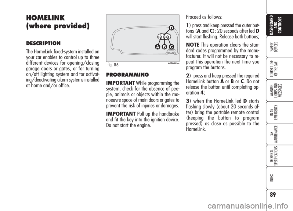
1) press and keep pressed the outer but-
tons (AandC): 20 seconds after led D
will start flashing. Release both buttons;
NOTEThis operation clears the stan-
dard codes programmed by the manu-
facturer. It will not be necessary to re-
peat this operation the next time you
program the buttons.
2) press and keep pressed the required
HomeLink button AorBorC. Do not
release the button until completing op-
eration4;
3) when the HomeLink led Dstarts
flashing slowly (about 20 seconds af-
ter) bring the portable remote control
(keeping the button to program
pressed) as close as possible to the
HomeLink.
89
SAFETY
DEVICES
WARNING
LIGHTS AND
MESSAGES
IN AN
EMERGENCY
CAR
MAINTENANCE
TECHNICAL
SPECIFICATIONS
INDEX
CORRECT USE
OF THE CAR
DASHBOARD
AND
CONTROLS
HOMELINK
(where provided)
DESCRIPTION
The HomeLink fixed-system installed on
your car enables to control up to three
different devices for opening/closing
garage doors or gates, or for turning
on/off lighting system and for activat-
ing/deactivating alarm systems installed
at home and/or office.
A0E0311mfig. 86