engine Alfa Romeo 159 2006 Owner handbook (in English)
[x] Cancel search | Manufacturer: ALFA ROMEO, Model Year: 2006, Model line: 159, Model: Alfa Romeo 159 2006Pages: 299, PDF Size: 4.64 MB
Page 26 of 299
24
SAFETY
DEVICES
WARNING LIGHTS
AND MESSAGES
IN AN
EMERGENCY
CAR
MAINTENANCE
TECHNICAL
SPECIFICATIONS
INDEX
DASHBOARD
AND
CONTROLS
CORRECT USE
OF THE CAR
Fitting the electronic key into the igni-
tion device will display the total km (or
mi), press button A-fig. 22for trip me-
ter (or mi).
To reset the trip meter (or mi), press for
long button A-fig. 22during display-
ing.
MULTIFUNCTION
DISPLAY
(where provided)
The “Multifunction display” shows all
the useful information necessary when
driving, more particularly:
INFORMATION ON
STANDARD SCREEN
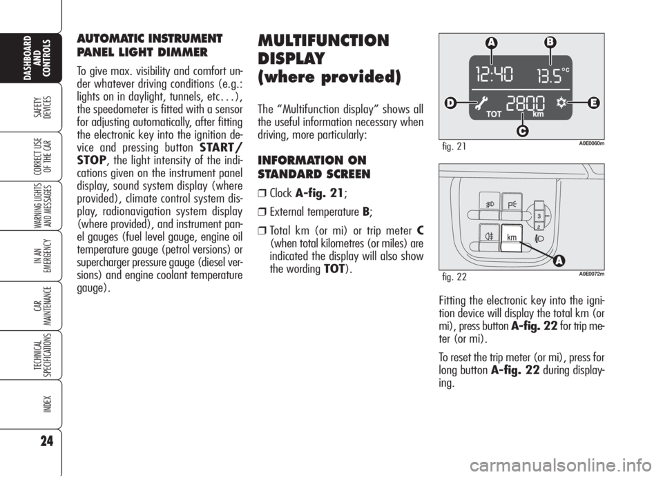
❒ClockA-fig. 21;
❒External temperature B;
❒Total km (or mi) or trip meter C
(when total kilometres (or miles) are
indicated the display will also show
the wording TOT).
A0E0060mfig. 21
A0E0072mfig. 22
AUTOMATIC INSTRUMENT
PANEL LIGHT DIMMER
To give max. visibility and comfort un-
der whatever driving conditions (e.g.:
lights on in daylight, tunnels, etc…),
the speedometer is fitted with a sensor
for adjusting automatically, after fitting
the electronic key into the ignition de-
vice and pressing button START/
STOP, the light intensity of the indi-
cations given on the instrument panel
display, sound system display (where
provided), climate control system dis-
play, radionavigation system display
(where provided), and instrument pan-
el gauges (fuel level gauge, engine oil
temperature gauge (petrol versions) or
supercharger pressure gauge (diesel ver-
sions) and engine coolant temperature
gauge).
Page 27 of 299
25
SAFETY
DEVICES
WARNING LIGHTS
AND MESSAGES
IN AN
EMERGENCY
CAR
MAINTENANCE
TECHNICAL
SPECIFICATIONS
INDEX
DASHBOARD
AND
CONTROLS
CORRECT USE
OF THE CAR
INFORMATION ABOUT CAR
CONDITIONS (at event)
❒Scheduled servicing (symbol õD-
fig. 21).
❒Instrument panel light dimmer.
❒Symbol of possible presence of ice on
the road (symbol
√E-fig. 21).
❒Speed limit exceeded.
❒Engine oil level.
A0E0074mfig. 23
“SETUP MENU”
There is also a “Setup Menu” enabling
to perform the adjustments and/or set-
tings described on the following pages
by pressing button MENUand+/–
(seefig. 23). The Setup can be acti-
vated by pressing briefly button MENU.
With the car stopped, the
following settings are
enabled:
❒Speed limit on/off and speed limit
value.
❒Clock.
❒Failure/warning buzzer volume.
❒“Distance” unit.
With the car running, only the
following setting is enabled:
❒Speed limit on/off and speed limit
value setting.
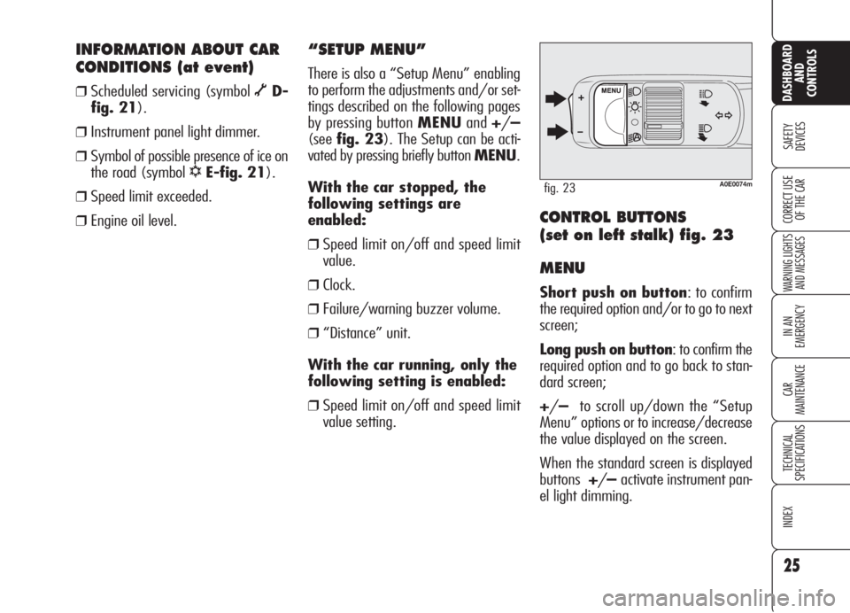
CONTROL BUTTONS
(set on left stalk) fig. 23
MENU
Short push on button: to confirm
the required option and/or to go to next
screen;
Long push on button: to confirm the
required option and to go back to stan-
dard screen;
+/–to scroll up/down the “Setup
Menu” options or to increase/decrease
the value displayed on the screen.
When the standard screen is displayed
buttons+/–activate instrument pan-
el light dimming.
Page 30 of 299
ENGINE OIL LEVEL
INDICATION
Fitting the electronic key into the igni-
tion device, the display will show for a
few seconds the engine oil level. At this
stage, to clear this indication and to go
to next screen, press button MENU.
Low oil level will be indicated by a ded-
icated warning message on the display.
IMPORTANT Check the proper en-
gine oil level on the dipstick (see para-
graph “Checking levels” in section “Car
maintenance”).
IMPORTANTProper engine oil level
shall be checked with the car on level
ground.
IMPORTANT To read the correct oil
level after fitting the electronic key, wait
for about 2 seconds before starting the
engine.
IMPORTANT Engine oil level could in-
crease after a long stop.
MESSAGES DISPLAYED
AT STARTING
After the engine oil level, the display will
show for a few seconds a message in-
dicating the procedure to follow to start
the engine (PRESS PEDAL AND
START: press brake or clutch pedal and
then press button START/STOPto
start the engine). Scheduled servicing
IMPORTANTThe Service schedule in-
cludes car maintenance every 30,000
km (or 18,000 mi); this is shown au-
tomatically, with the electronic key in-
to the ignition device starting from
2,000 km (or 1,240 mi) from this
deadline and it will be displayed in km
or miles according to the unit set. When
a scheduled service interval (“coupon”)
is near to come, fitting the electronic key
into the ignition device will display a
message followed by the number of
km/mi to go before car servicing. Con-
tact Alfa Romeo Authorized Services to
carry out any service operation provid-
ed by the Service schedule or by the An-
nual inspection plan, and to reset the
display.
28
SAFETY
DEVICES
WARNING LIGHTS
AND MESSAGES
IN AN
EMERGENCY
CAR
MAINTENANCE
TECHNICAL
SPECIFICATIONS
INDEX
CORRECT USE
OF THE CAR
DASHBOARD
AND
CONTROLS
Page 32 of 299
30
SAFETY
DEVICES
WARNING LIGHTS
AND MESSAGES
IN AN
EMERGENCY
CAR
MAINTENANCE
TECHNICAL
SPECIFICATIONS
INDEX
DASHBOARD
AND
CONTROLS
CORRECT USE
OF THE CARThe date Cin the middle of the display
will stay on until another display info is
activated (e.g. “Light dimmer”) or oth-
er information on car conditions.
With key removed (when opening when
of the front doors) the display will turn
on and show for a few seconds the time,
covered km (or miles) and outside tem-
perature.
INFORMATION ABOUT CAR
CONDITIONS (at event)
❒Scheduled servicing;
❒Trip computer;
❒Instrument panel light dimmer;
❒Engine oil level;
IMPORTANTWhen opening one of
the front doors, the display will show for
a few seconds the time, the km covered
and the external temperature.
RECONFIGURABLE
MULTIFUNCTION
DISPLAY
(where provided)
The “Reconfigurable multifunction dis-
play” shows all the useful information
necessary when driving, more particu-
larly:
INFORMATION ON
STANDARD SCREEN
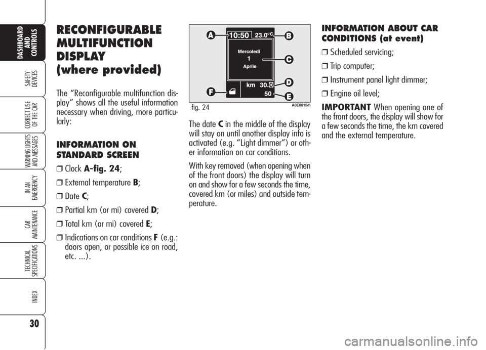
❒ClockA-fig. 24;
❒External temperature B;
❒DateC;
❒Partial km (or mi) covered D;
❒Total km (or mi) covered E;
❒Indications on car conditions F(e.g.:
doors open, or possible ice on road,
etc. ...).
A0E0015mfig. 24
Page 34 of 299
32
SAFETY
DEVICES
WARNING LIGHTS
AND MESSAGES
IN AN
EMERGENCY
CAR
MAINTENANCE
TECHNICAL
SPECIFICATIONS
INDEX
DASHBOARD
AND
CONTROLS
CORRECT USE
OF THE CAR
Selecting “Date” and “Clock”:
❒briefly press button MENUto select
the first value to change (e.g. hours/
minutes or year/month/day);
❒operate buttons +or–(by single
press) to select the new setting;
❒briefly press button MENUto store
the new setting and to go to the next
setup menu option, if this is the last
one you will go back to the previously
selected option of the main menu.
ENGINE OIL LEVEL
INDICATION
Fitting the electronic key into the igni-
tion device, the display will show for a
few seconds the engine oil level. At this
stage, to clear this indication and to go
to next screen, press button MENU.
Low oil level will be indicated by a ded-
icated warning message on the display.
IMPORTANT Check the proper en-
gine oil level on the dipstick (see para-
graph “Checking levels” in section “Car
maintenance”).
IMPORTANTProper engine oil level
shall be checked with the car on level
ground.
IMPORTANT To read the correct oil
level after fitting the electronic key, wait
for about 2 seconds before starting the
engine.
IMPORTANT Engine oil level could in-
crease after a long stop. Selecting an option of the main
menu with submenu:❒briefly press button MENUto display
the first submenu option;
❒operate buttons +or–(by single
press) to scroll all submenu options;
❒briefly press button MENUto select
the displayed submenu option and to
enter the corresponding setup menu;
❒operate buttons +or–(by single
press) to select the new setting of this
submenu option;
❒briefly press button MENUto store
the new setting and go back to the
previously selected submenu option.
Page 44 of 299
42
SAFETY
DEVICES
WARNING LIGHTS
AND MESSAGES
IN AN
EMERGENCY
CAR
MAINTENANCE
TECHNICAL
SPECIFICATIONS
INDEX
DASHBOARD
AND
CONTROLS
CORRECT USE
OF THE CAR
Values displayed
Average consumption
This value shows the average con-
sumption from the start of the new mis-
sion.
Current consumption
This value shows instant fuel consump-
tion (this value is updated second by
second). If parking the car with engine
on, the display will show “- - - -”.
Average speed
This value shows the car average speed
as a function of the overall time elapsed
since the start of the new mission.
Travel time
This value shows the time elapsed since
the start of the new mission (driving
time).
Range
This value shows the distance in km (or
mi) that the car can still cover before
needing fuel, assuming that driving con-
ditions are kept unvaried.The display will show “- - - -“ in the fol-
lowing cases:
❒value lower than 50 km (30mi);
❒car left parked with engine running
for over 5 minutes.
Travel Distance
This value shows the distance covered
from the start of the new mission.
Each time the battery is connected and
each time a new mission is started (re-
set), the display will show “0.0”.
IMPORTANTLacking information,
Trip computer values are displayed with
“- - - -”. When normal operating condi-
tion is reset, calculation of different units
will restart regularly. Values displayed
before the failure will not be reset. The “General Trip” displays the figures
relating to:
❒Average consumption
❒Current consumption
❒Average speed
❒Travel time
❒Range
❒Travel Distance
“Trip B” displays information concern-
ing:
❒Travel Distance B
❒Average consumption B
❒Average speed B
❒Travel time B.
Page 47 of 299
Reset Trip B
As concerns the Trip B values, it is pos-
sible to select through the “Setup
Menu” the reset mode (Manual or Au-
tomatic) (see paragraph “Setup Menu”
on previous pages):
❒manual reset: press and keep pressed
buttonTRIPfor over 2 seconds.
❒automatic reset: it takes place each
time the electronic key is fitted into
the ignition device.
At Trip B reset a warning message will
be displayed.
IMPORTANTTrip B reset will not re-
set “Range” and “Current Consump-
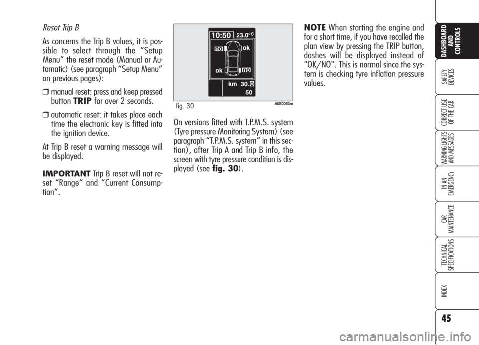
tion”.On versions fitted with T.P.M.S. system
(Tyre pressure Monitoring System) (see
paragraph “T.P.M.S. system” in this sec-
tion), after Trip A and Trip B info, the
screen with tyre pressure condition is dis-
played (see fig. 30).
45
SAFETY
DEVICES
WARNING LIGHTS
AND MESSAGES
IN AN
EMERGENCY
CAR
MAINTENANCE
TECHNICAL
SPECIFICATIONS
INDEX
CORRECT USE
OF THE CAR
DASHBOARD
AND
CONTROLS
A0E0053mfig. 30
NOTEWhen starting the engine and
for a short time, if you have recalled the
plan view by pressing the TRIP button,
dashes will be displayed instead of
"OK/NO". This is normal since the sys-
tem is checking tyre inflation pressure
values.
Page 58 of 299
56
SAFETY
DEVICES
WARNING
LIGHTS AND
MESSAGES
IN AN
EMERGENCY
CAR
MAINTENANCE
TECHNICAL
SPECIFICATIONS
INDEX
CORRECT USE
OF THE CAR
DASHBOARD
AND
CONTROLS
QUICK WINDSCREEN
AND FRONT SIDE WINDOW
DEMISTING/DEFROSTING
(MAX-DEF function)
Press button -: the button leds -,
√and(will turn on. To turn this func-
tion off, press again button
-the but-
ton led will turn off. After defrosting, turn
the function off to keep top comfort con-
ditions.
Window demisting
Climate control system
√is very use-
ful to speed up window demisting and
it is therefore to be turned on in the
event of considerable moisture. In any
case it is recommended to perform the
following preventive demisting proce-
dure:
❒turn air recirculation off (if on);
❒turn knob Cto second speed;
❒turn knob BtoQ.
HEATED REAR WINDOW
AND DOOR MIRROR
DEMISTING/DEFROSTING
Press button (to activate the demist-
ing/defrosting function: when this func-
tion is on, the circular led around the but-
ton will turn on.
On certain versions, turning this function
on will also activate windscreen de-
frosting in the windscreen wiper area.
This function is timed and switches off
automatically after few minutes, or by
pressing again the button or by turning
the engine off. It will not be switched
on automatically when restarting the en-
gine.
IMPORTANTDo not apply stickers on
the inside of the heated rear window
over the heating filaments to avoid dam-
age that might cause it to stop work-
ing properly.
WARMING THE PASSENGER
COMPARTMENT
Proceed as follows:
❒turn knob Ato the required temper-
ature;
❒turn knob Cto the required speed;
❒turn knob Bto the required distribu-
tion:
N: to warm the feet of front and rear
passengers;
M: to warm the feet and keep the face
cool (bilevel function);
Q: to warm the feet and at the same
time demist the windscreen;
❒turn air recirculation off (if on).
Page 60 of 299
58
SAFETY
DEVICES
WARNING
LIGHTS AND
MESSAGES
IN AN
EMERGENCY
CAR
MAINTENANCE
TECHNICAL
SPECIFICATIONS
INDEX
CORRECT USE
OF THE CAR
DASHBOARD
AND
CONTROLS
To guarantee perfect
and regular sensor op-
eration do not apply
stickers in the “monitoring”
area between sensor and wind-
screen. Keep windscreen and
sensor clean and avoid to accu-
mulate dust or other sub-
stances.
AUTOMATIC TWO-/
THREE-ZONE
CLIMATE CONTROL
SYSTEM
(where provided)
DESCRIPTION
The car is fitted with a two-/three-zone
climate control system which makes it
possible to separately adjust the air tem-
perature in the two/three passenger’s
compartment areas to reach the required
comfort.
For top quality temperature control in
the two/three areas of the passenger's
compartment, the system is fitted with
external temperature sensor, passen-
ger's compartment temperature sensor
and two-side sun radiation sensor.
The climate control system automatically
controls and adjusts the following pa-
rameters and functions:
❒air temperature at driver/passengers
vents;
❒fan speed;
❒air distribution at driver/passenger
vents;
❒compressor activation;
❒air recirculation.
The following parameters and functions
can be set or changed manually:
❒required temperature;
❒fan speed;
❒air distribution on seven levels ;
❒compressor on/off;
❒window demisting/defrosting;
❒air recirculation;
❒one-zone function.
The system is fitted with AQS (Air Qual-
ity System) sensor (where provided),
that turns on air recirculation automati-
cally when it detects the presence of out-
side polluted air (for example in queues
and tunnels).
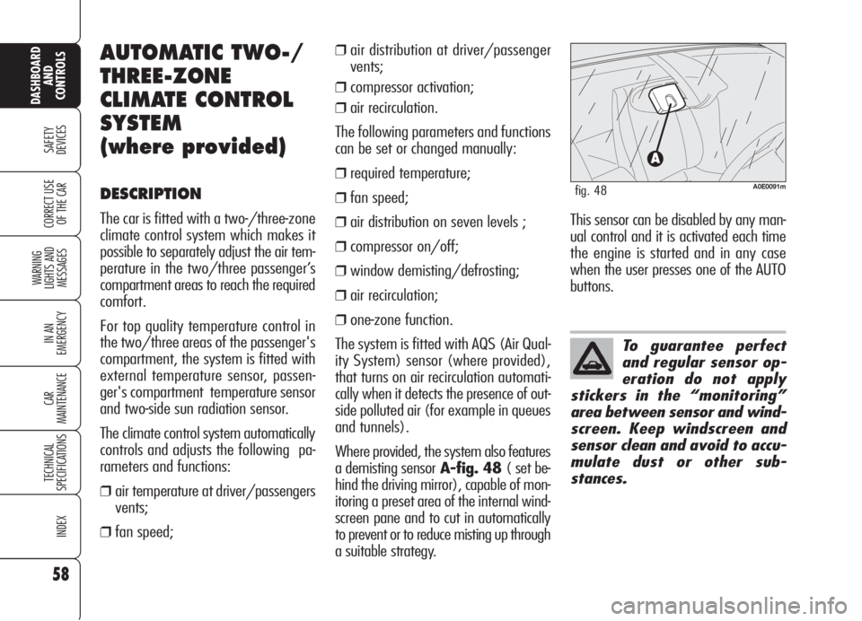
Where provided, the system also features
a demisting sensorA-fig. 48 ( set be-
hind the driving mirror), capable of mon-
itoring a preset area of the internal wind-
screen pane and to cut in automatically
to prevent or to reduce misting up through
a suitable strategy.
A0E0091mfig. 48
This sensor can be disabled by any man-
ual control and it is activated each time
the engine is started and in any case
when the user presses one of the AUTO
buttons.
Page 64 of 299
62
SAFETY
DEVICES
WARNING
LIGHTS AND
MESSAGES
IN AN
EMERGENCY
CAR
MAINTENANCE
TECHNICAL
SPECIFICATIONS
INDEX
CORRECT USE
OF THE CAR
DASHBOARD
AND
CONTROLS
LO (LOW) function
(highest cooling power)
It is switched on by setting a tempera-
ture lower than 16°C on the display;
this setting is shown on the display. This
function can be switched on when you
wish to cool the passenger compartment
as quickly as possible, by taking the
greatest advantage from the system po-
tential.
The function cuts off air heating, switch-
es on both internal air recirculation (to
prevent hot air from entering the com-
partment) and the climate control com-
pressor, brings air distribution to
¯/˙
and the fan speed is controlled auto-
matically by the system. With the function switched on, howev-
er, all the manual settings can be made.
To switch the function off, you only need
to turn the ring of knob B/E/Pof the
temperature set to a value higher than
16°C; the opposite display and the rear
display (where provided) will show
16°C.
Pressing button AUTO, the display will
show a temperature of 16°C and re-
turns to an operating condition with au-
tomatic temperature adjustment. This function should not be ac-
tivated when the engine is cold,
to prevent air not warm enough
from entering the passenger
compartment.
With the function switched on, howev-
er, all the manual settings can be made.
To switch the function off, you only need
to turn the ring of knob (BorE/P) of
the temperature set to a value lower
than 32°C; the opposite display and the
rear display (where provided) will show
32°C.
Pressing button AUTO, the display will
show a temperature of 32°C and re-
turns to an operating condition with au-
tomatic temperature adjustment.