lock Alfa Romeo 159 2006 Owner handbook (in English)
[x] Cancel search | Manufacturer: ALFA ROMEO, Model Year: 2006, Model line: 159, Model: Alfa Romeo 159 2006Pages: 299, PDF Size: 4.64 MB
Page 48 of 299
Upholstery of your car
has been designed to
withstand wear deriv-
ing from common use of the car.
You are however recommended
to avoid strong and/or contin-
uous scratching with clothing
accessories such as metallic
buckles, studs, Velcro fasten-
ings and the like, since these
items cause circumscribed stress
of the cover fabric that could
lead to yarn breaking, and dam-
age the cover as a consequence.
46
SAFETY
DEVICES
WARNING
LIGHTS AND
MESSAGES
IN AN
EMERGENCY
CAR
MAINTENANCE
TECHNICAL
SPECIFICATIONS
INDEX
CORRECT USE
OF THE CAR
DASHBOARD
AND
CONTROLS
Height adjustment
(where provided)
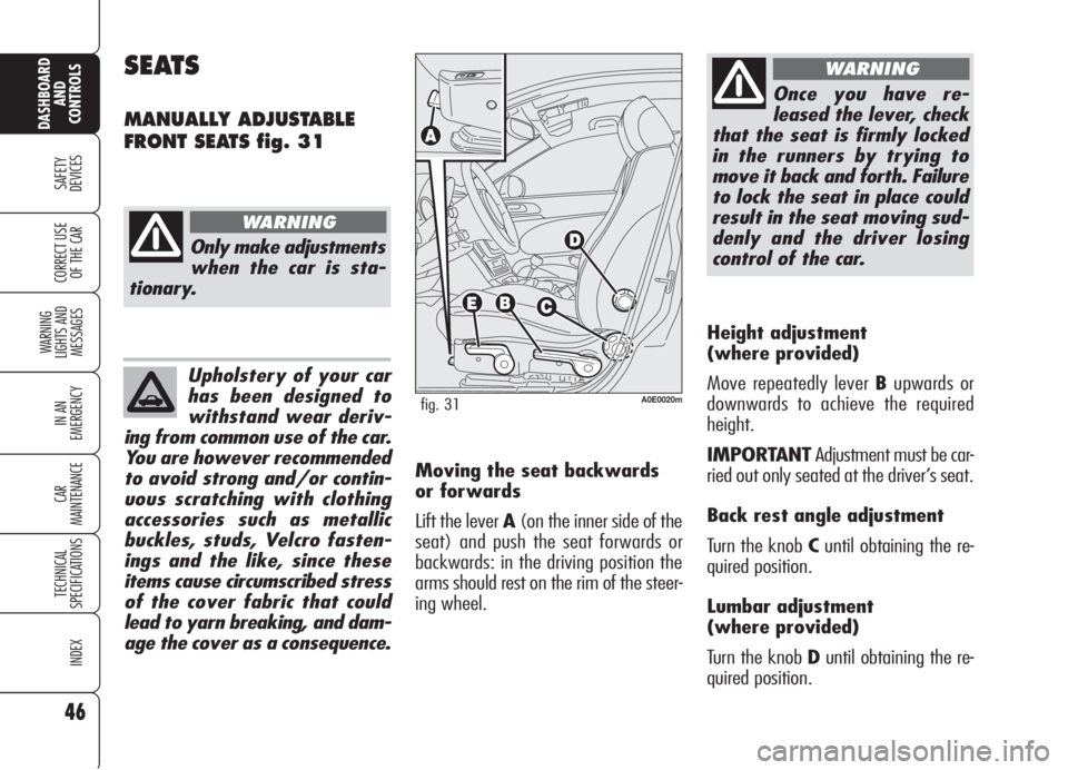
Move repeatedly lever Bupwards or
downwards to achieve the required
height.
IMPORTANTAdjustment must be car-
ried out only seated at the driver’s seat.
Back rest angle adjustment
Turn the knob Cuntil obtaining the re-
quired position.
Lumbar adjustment
(where provided)
Turn the knob Duntil obtaining the re-
quired position.
SEATS
MANUALLY ADJUSTABLE
FRONT SEATS fig. 31
Only make adjustments
when the car is sta-
tionary.
WARNING
A0E0020mfig. 31
Once you have re-
leased the lever, check
that the seat is firmly locked
in the runners by trying to
move it back and forth. Failure
to lock the seat in place could
result in the seat moving sud-
denly and the driver losing
control of the car.
WARNING
Moving the seat backwards
or forwards
Lift the lever A(on the inner side of the
seat) and push the seat forwards or
backwards: in the driving position the
arms should rest on the rim of the steer-
ing wheel.
Page 50 of 299
48
SAFETY
DEVICES
WARNING
LIGHTS AND
MESSAGES
IN AN
EMERGENCY
CAR
MAINTENANCE
TECHNICAL
SPECIFICATIONS
INDEX
CORRECT USE
OF THE CAR
DASHBOARD
AND
CONTROLS
HEAD RESTRAINTS
FRONT HEAD RESTRAINTS
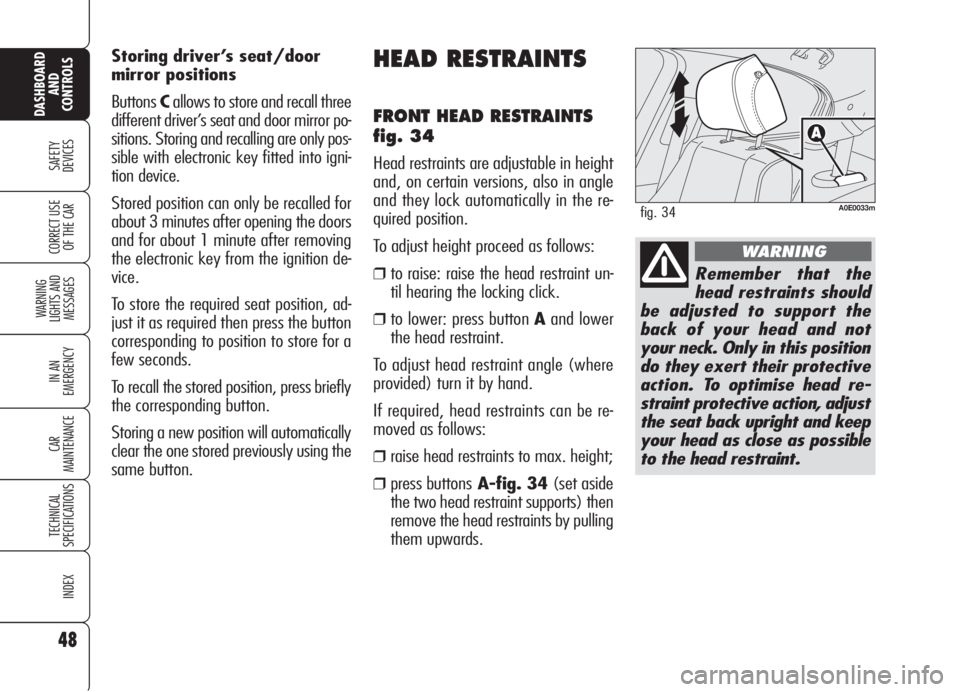
fig. 34
Head restraints are adjustable in height
and, on certain versions, also in angle
and they lock automatically in the re-
quired position.
To adjust height proceed as follows:
❒to raise: raise the head restraint un-
til hearing the locking click.
❒to lower: press button Aand lower
the head restraint.
To adjust head restraint angle (where
provided) turn it by hand.
If required, head restraints can be re-
moved as follows:
❒raise head restraints to max. height;
❒press buttonsA-fig. 34(set aside
the two head restraint supports) then
remove the head restraints by pulling
them upwards. Storing driver’s seat/door
mirror positions
ButtonsCallows to store and recall three
different driver’s seat and door mirror po-
sitions. Storing and recalling are only pos-
sible with electronic key fitted into igni-
tion device.
Stored position can only be recalled for
about 3 minutes after opening the doors
and for about 1 minute after removing
the electronic key from the ignition de-
vice.
To store the required seat position, ad-
just it as required then press the button
corresponding to position to store for a
few seconds.
To recall the stored position, press briefly
the corresponding button.
Storing a new position will automatically
clear the one stored previously using the
same button.
A0E0033mfig. 34
Remember that the
head restraints should
be adjusted to support the
back of your head and not
your neck. Only in this position
do they exert their protective
action. To optimise head re-
straint protective action, adjust
the seat back upright and keep
your head as close as possible
to the head restraint.
WARNING
Page 51 of 299
49
SAFETY
DEVICES
WARNING
LIGHTS AND
MESSAGES
IN AN
EMERGENCY
CAR
MAINTENANCE
TECHNICAL
SPECIFICATIONS
INDEX
CORRECT USE
OF THE CAR
DASHBOARD
AND
CONTROLS
REAR HEAD RESTRAINTS
Rear seats are fitted with two head re-
straints.
Certain versions are fitted with height-ad-
justable head restraint also for the central
seat (see previous paragraph for height
adjustment).
If required, head restraints can be re-
moved as follows:
❒raise head restraints to max. height;
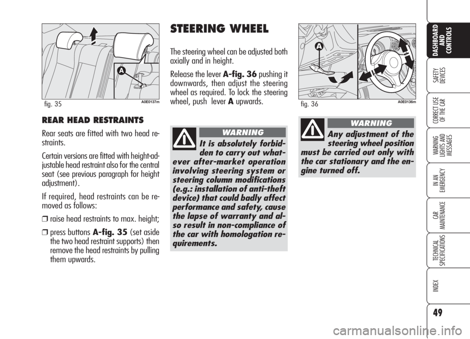
❒press buttonsA-fig. 35(set aside
the two head restraint supports) then
remove the head restraints by pulling
them upwards.
STEERING WHEEL
The steering wheel can be adjusted both
axially and in height.
Release the lever A-fig. 36pushing it
downwards, then adjust the steering
wheel as required. To lock the steering
wheel, push lever Aupwards.
A0E0137mfig. 35
It is absolutely forbid-
den to carry out what-
ever after-market operation
involving steering system or
steering column modifications
(e.g.: installation of anti-theft
device) that could badly affect
performance and safety, cause
the lapse of warranty and al-
so result in non-compliance of
the car with homologation re-
quirements.
WARNING
A0E0136mfig. 36
Any adjustment of the
steering wheel position
must be carried out only with
the car stationary and the en-
gine turned off.
WARNING
Page 63 of 299
61
SAFETY
DEVICES
WARNING
LIGHTS AND
MESSAGES
IN AN
EMERGENCY
CAR
MAINTENANCE
TECHNICAL
SPECIFICATIONS
INDEX
CORRECT USE
OF THE CAR
DASHBOARD
AND
CONTROLS
AIR TEMPERATURE
ADJUSTMENT KNOBS
Turning the knob knurled rings (B/
E/P), clockwise or counter-clockwise,
respectively raises or lowers the tem-
perature of the air required respective-
ly in the left front zone (knob B) or right
front zone (knob E) or rear zone (knob
P) of the passenger compartment. The
temperatures set are shown on the dis-
playD/S.
Turning the knob knurled rings fully
clockwise or counter-clockwise until they
reach the extreme selections HIorLO,
the maximum heating or cooling func-
tions are respectively engaged.HI function (HIGH)
(maximum heating power)
It is switched on by setting a tempera-
ture of more than 32°C on the display,
and can be switched on independently
from the driver’s or passengers’ side, or
both of them; this setting brings the sys-
tem to the “one-zone” mode and it is
shown by both displays.
This functions can be switched on when
you wish to heat the passenger com-
partment as quickly as possible, by tak-
ing the greatest advantage from the sys-
tem potential.
The function uses the maximum tem-
perature of the heating fluid, whereas
air distribution and fan speed are con-
trolled automatically by the system.
SWITCHING THE CLIMATE
CONTROL SYSTEM ON
The system can be turned on by press-
ing any button (excluding
(,vand
MONO); it is however advisable to set
the required temperatures on the display
and then to press the AUTO button.
The climate control system allows to per-
sonalise required temperatures (driver and
passengers).
Page 70 of 299

68
SAFETY
DEVICES
WARNING
LIGHTS AND
MESSAGES
IN AN
EMERGENCY
CAR
MAINTENANCE
TECHNICAL
SPECIFICATIONS
INDEX
CORRECT USE
OF THE CAR
DASHBOARD
AND
CONTROLS
POLLEN FILTER/ ACTIVATED
CARBON POLLEN FILTER
According to versions, the car can be fit-
ted with pollen filter or activated carbon
pollen filter (where provided). The filter
has the specific capability of admitting to
the passenger compartment purified air,
free from particles such as dust, pollen,
etc. The filtering action takes place un-
der all air inlet conditions and it is clear-
ly most effective with the windows shut.
Have the conditions of the filter checked
by Alfa Romeo Authorized Services at
least once a year, preferably at the on-
set of summer. If the car is used main-
ly in polluted or dusty areas it should be
checked and if necessary replaced at
shorter intervals than specified in the
Service Schedule (see section “Car
Maintenance”). AQS function (Air Quality
System) (where provided)
The AQS function turns on automatical-
ly air recirculation when it detects the
presence of polluted air (e.g. in queues
and tunnels).
IMPORTANTWith AQS function on,
after a preset time with recirculation on,
the compressor will enable outside air
inlet (for about 1 minute) to change air
inside the passenger compartment, re-
gardless of outside air pollution level.
IMPORTANTThe AQS function is dis-
abled when the outside temperature is
cold to prevent window misting up. To
reactivate this function, press button
v. Led “A” on button vwill
turn on to indicate that the function is
on.
Failure to replace the fil-
ter may considerably re-
duce the effectiveness of
the climate control system up to
blocking the air flow from the
outlets and vents.
In certain weather con-
ditions (e.g. outside
temperature around
0°C) and with automatic air re-
circulation control on, mist may
form on the windows. In this
case press button vto
switch off recirculation and if
necessary press button + to in-
crease the flow of air to the
windscreen.
With the outside tem-
perature below -1°C the
climate control compres-
sor is unable to work. It is
therefore inadvisable to use the
inside air recirculation function
with low outside temperature
as windows may mist over
quickly.
Page 81 of 299
79
SAFETY
DEVICES
WARNING
LIGHTS AND
MESSAGES
IN AN
EMERGENCY
CAR
MAINTENANCE
TECHNICAL
SPECIFICATIONS
INDEX
CORRECT USE
OF THE CAR
DASHBOARD
AND
CONTROLS
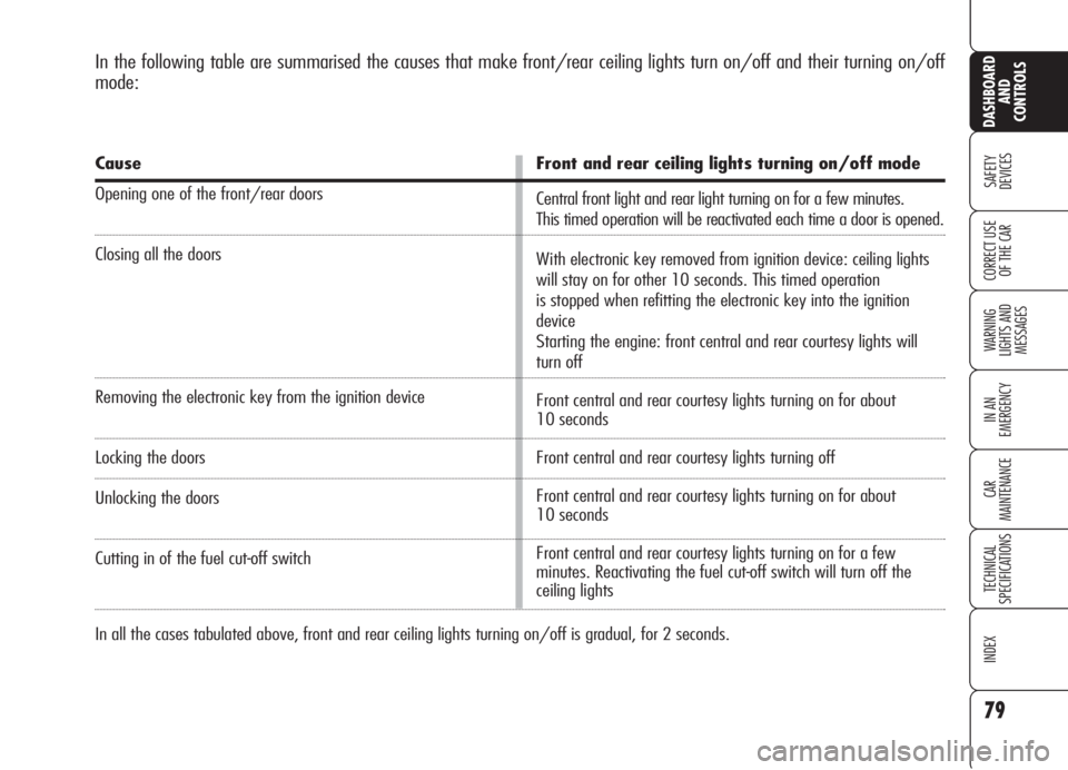
In the following table are summarised the causes that make front/rear ceiling lights turn on/off and their turning on/off
mode:
Cause
Opening one of the front/rear doors
Closing all the doors
Removing the electronic key from the ignition device
Locking the doors
Unlocking the doors
Cutting in of the fuel cut-off switch
Front and rear ceiling lights turning on/off mode
Central front light and rear light turning on for a few minutes.
This timed operation will be reactivated each time a door is opened.
With electronic key removed from ignition device: ceiling lights
will stay on for other 10 seconds. This timed operation
is stopped when refitting the electronic key into the ignition
device
Starting the engine: front central and rear courtesy lights will
turn off
Front central and rear courtesy lights turning on for about
10 seconds
Front central and rear courtesy lights turning off
Front central and rear courtesy lights turning on for about
10 seconds
Front central and rear courtesy lights turning on for a few
minutes. Reactivating the fuel cut-off switch will turn off the
ceiling lights
In all the cases tabulated above, front and rear ceiling lights turning on/off is gradual, for 2 seconds.
Page 83 of 299
81
SAFETY
DEVICES
WARNING
LIGHTS AND
MESSAGES
IN AN
EMERGENCY
CAR
MAINTENANCE
TECHNICAL
SPECIFICATIONS
INDEX
CORRECT USE
OF THE CAR
DASHBOARD
AND
CONTROLS
CONTROLS
POWER SUPPLY AND FUEL
CUT-OFF SWITCHES
The car is fitted with a safety switch that
in the event of a crash comes into op-
eration by cutting off fuel and turning
off the engine as a consequence.
Certain versions are equipped with an
additional safety switch that in the event
of a crash comes into operation by cut-
ting off the power supply.
These two safety switches therefore pre-
vent dangerous fuel leaks due to fuel
line cracking, and sparks or electric dis-
charges due to damaging or malfunc-
tioning of the electric components of the
car in the event of a crash.
IMPORTANTAfter a crash, remem-
ber to remove the key from the ignition
device to prevent battery run-down.
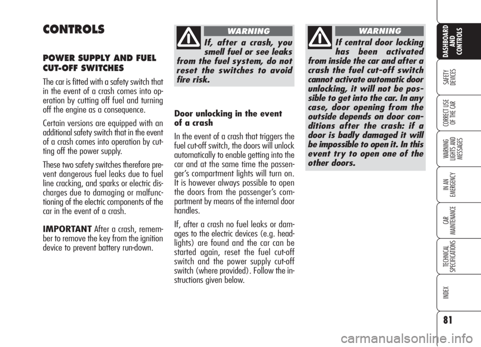
If, after a crash, you
smell fuel or see leaks
from the fuel system, do not
reset the switches to avoid
fire risk.
WARNING
If central door locking
has been activated
from inside the car and after a
crash the fuel cut-off switch
cannot activate automatic door
unlocking, it will not be pos-
sible to get into the car. In any
case, door opening from the
outside depends on door con-
ditions after the crash: if a
door is badly damaged it will
be impossible to open it. In this
event try to open one of the
other doors.
WARNING
Door unlocking in the event
of a crash
In the event of a crash that triggers the
fuel cut-off switch, the doors will unlock
automatically to enable getting into the
car and at the same time the passen-
ger’s compartment lights will turn on.
It is however always possible to open
the doors from the passenger’s com-
partment by means of the internal door
handles.
If, after a crash no fuel leaks or dam-
ages to the electric devices (e.g. head-
lights) are found and the car can be
started again, reset the fuel cut-off
switch and the power supply cut-off
switch (where provided). Follow the in-
structions given below.
Page 87 of 299
85
SAFETY
DEVICES
WARNING
LIGHTS AND
MESSAGES
IN AN
EMERGENCY
CAR
MAINTENANCE
TECHNICAL
SPECIFICATIONS
INDEX
CORRECT USE
OF THE CAR
DASHBOARD
AND
CONTROLS
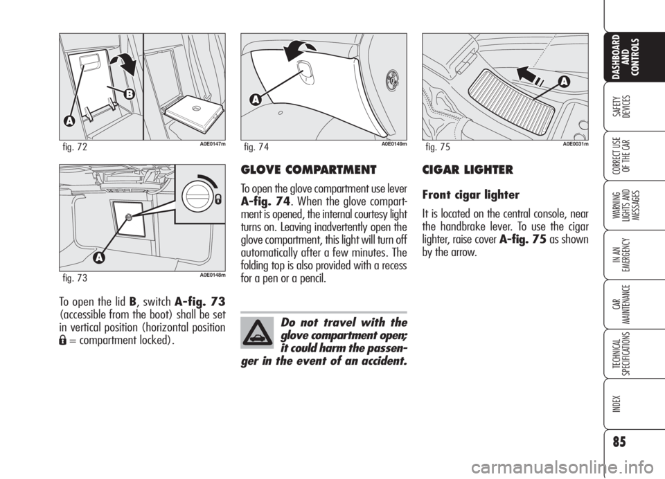
To open the lid B, switch A-fig. 73
(accessible from the boot) shall be set
in vertical position (horizontal position
Á= compartment locked).
A0E0148mfig. 73
A0E0147mfig. 72
GLOVE COMPARTMENT
To open the glove compartment use lever
A-fig. 74. When the glove compart-
ment is opened, the internal courtesy light
turns on. Leaving inadvertently open the
glove compartment, this light will turn off
automatically after a few minutes. The
folding top is also provided with a recess
for a pen or a pencil.
A0E0149mfig. 74
Do not travel with the
glove compartment open;
it could harm the passen-
ger in the event of an accident.
CIGAR LIGHTER
Front cigar lighter
It is located on the central console, near
the handbrake lever. To use the cigar
lighter, raise cover A-fig. 75as shown
by the arrow.
A0E0031mfig. 75
Page 96 of 299

94
SAFETY
DEVICES
WARNING
LIGHTS AND
MESSAGES
IN AN
EMERGENCY
CAR
MAINTENANCE
TECHNICAL
SPECIFICATIONS
INDEX
CORRECT USE
OF THE CAR
DASHBOARD
AND
CONTROLS
SUN CURTAIN fig. 88
The sun curtain shall be used to adjust
brightness inside the passenger com-
partment. Sun curtain is fitted with han-
dle and air vents. If when removing the key from the ig-
nition device, you activate sunroof slid-
ing by pressing the electronic key but-
ton
ËorÁwhile sunroof sliding by man-
ual control (by pressing the selector) is
being performed, this last control will
prevail. To make the sunroof sliding au-
tomatically you have to press again but-
ton
ËorÁ.
Sunroof sliding by pressing the electronic
key buttons
ËorÁcan be stopped by op-
erating selector A-fig. 87(by changing
its position or pressing it).
Changing selector position, will make
the sunroof slide to the new position ig-
noring buttons
ËorÁ.
Open and close the roof
only when the vehicle
is stationary.
WARNING
A0E0070mfig. 88
SUNROOF CLOSING
Closing from inside the car
Turn selector A-fig. 87counter-clock-
wise.
Closing from outside the car
Press the electronic key button
Áfor
over 2 seconds.
During sunroof closing stroke, the anti-
crushing safety system is active along
the whole stroke (excluding the last 4
mm). The anti-crushing safety system is
always active when sunroof is closed by
pressing button
Á.
Though the selector (by pressing it) it is
possible to use the “Inhibit” position
that will exclude the anti-crushing safe-
ty system.
Page 97 of 299

95
SAFETY
DEVICES
WARNING
LIGHTS AND
MESSAGES
IN AN
EMERGENCY
CAR
MAINTENANCE
TECHNICAL
SPECIFICATIONS
INDEX
CORRECT USE
OF THE CAR
DASHBOARD
AND
CONTROLS
ANTI-CRUSHING SAFETY
SYSTEM
The anti-crushing safety system fitted on
the front curtain outline is active during
horizontal closing (front edge) and ver-
tical closing of the panel (rear edge) and
it will cut in when it finds an obstacle
(e.g.: finger, hand, etc …), thus guar-
anteeing sunroof reversal for a short sec-
tion.
When an obstacle is found, sunroof
stroke is stopped immediately and its
stroke is reversed to the preset position:
❒during horizontal closing it is active
along the whole stroke of the sunroof
and when it finds an obstacle on the
front side of the pane it guarantees
a 10 cm stroke reversal;
❒during vertical closing it is active
along the whole stroke of the sunroof
and when it finds an obstacle on the
rear side of the pane it guarantees
stroke reversal.
EMERGENCY OPERATION
In a emergency or during servicing (with-
out power supply), the sunroof can be
operated manually; proceed as follows:
❒press the light notches to release the
clips and remove the front ceiling light
A-fig. 89.
❒fit the setscrew wrench into the prop-
er slot B;
❒turn the key to open or to close (ac-
cording to rotation direction) the sun-
roof.
SUNROOF INITIALISATION
PROCEDURE
After disconnecting the battery or failing
the protection fuse, the sunroof shall be
“initialised” again, proceed as follows:
❒turn selector fully leftwards (counter-
clokwise);
❒press and keep pressed selector until
sunroof locking;
❒release selector;
❒press selector again within 3 seconds,
and keep it pressed;
❒a few seconds after the sunroof will
move automatically (during this stage
keep on pressing the knob);
❒initialisation will end when the sun-
roof stops. Release selector.
A0E0187mfig. 89