ignition Alfa Romeo 159 2006 Owner handbook (in English)
[x] Cancel search | Manufacturer: ALFA ROMEO, Model Year: 2006, Model line: 159, Model: Alfa Romeo 159 2006Pages: 299, PDF Size: 4.64 MB
Page 76 of 299
74
SAFETY
DEVICES
WARNING
LIGHTS AND
MESSAGES
IN AN
EMERGENCY
CAR
MAINTENANCE
TECHNICAL
SPECIFICATIONS
INDEX
CORRECT USE
OF THE CAR
DASHBOARD
AND
CONTROLS
Turning the knurled ringA-fig. 54it
is possible to increase the sensitivity of
the rain sensor, obtaining a quicker
change from stationary (no wiping)
when the windscreen is dry, to first con-
tinuous speed (continuous, slow). A fur-
ther stroke will confirm operation.
Operating the windscreen washer with
the rain sensor activated (stalk at posi-
tion1-fig. 54) the normal washing
cycle is performed at the end of which
the rain sensor resumes its normal au-
tomatic function.
Removing the electronic key from the
ignition device, the rain sensor is deac-
tivated and the next time the engine is
started it will not be reactivated even if
the stalk has remained in position 1-
fig. 54. In this case to activate the rain
sensor, simply move the stalk to 0or2
and then back to 1.
When the rain sensor is reactivated in
this way, the wiper performs one stroke,
even if the windscreen is dry, to indicate
that reactivation has occurred. “Smart washing” function
Pulling the lever towards the steering
wheel (unstable position) operates the
windscreen washer.
Keeping the stalk pulled with just one
movement it is possible to operate the
washer jet and the wiper at the same
time; the wiper actually comes into op-
eration automatically when the stalk is
pulled for more than half a second.
The wiper stops working 3 strokes after
releasing the stalk; a further stroke af-
ter about 6 seconds will complete the
wiping operation.
RAIN SENSOR
(where provided)
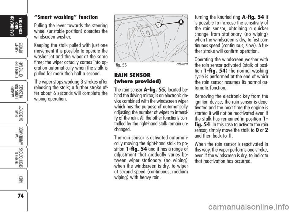
The rain sensor A-fig. 55, located be-
hind the driving mirror, is an electronic de-
vice combined with the windscreen wiper
which has the purpose of automatically
adjusting the number of wipes to intensi-
ty of the rain. All the other functions con-
trolled by the right-hand stalk remain un-
changed.
The rain sensor is activated automati-
cally moving the right-hand stalk to po-
sition1-fig. 54and it has a range of
adjustment that gradually varies be-
tween wiper stationary (no wiping)
when the windscreen is dry, to wiper
at second speed (continuous, medium
wiping) with heavy rain.
A0E0227mfig. 55
Page 79 of 299
77
SAFETY
DEVICES
WARNING
LIGHTS AND
MESSAGES
IN AN
EMERGENCY
CAR
MAINTENANCE
TECHNICAL
SPECIFICATIONS
INDEX
CORRECT USE
OF THE CAR
DASHBOARD
AND
CONTROLS
❒pressing the brake pedal, pressing the
clutch pedal (in these cases the last
stored speed will stay memorised, to
resume it press button RES);
❒pressing the accelerator pedal; in this
case the system is disengaged only
temporarily; device operation will be
resumed automatically when releas-
ing the pedal;
❒with car speed below the preset lim-
it (in these cases the last stored
speed will stay memorised, to resume
it press button RES);
Automatic Cruise Control
deactivation
The Cruise Control is temporarily deac-
tivated when the ABS or VDC systems
come into operation (above a max. pre-
set time): in this case the last set speed
will stay memorised, to recall it press
buttonRES.
In the event of Cruise Control or engine
control system failure, the device is de-
activated until removing the electronic
key from the ignition device. In this
event contact Alfa Romeo Authorized
Services.
❒engage the gear selected at the time
of speed memorising (4th or 5th
gear);
❒press the RESbutton (set at stalk
end).
TO INCREASE THE
MEMORISED SPEED
The speed memorised can be increased
in two ways:
❒pressing the accelerator and then
memorising the new speed reached;
or
❒moving the stalk upwards (+).
Each operation of the stalk will corre-
spond to a slight increase in speed
(about 1.5 km/h), while keeping the
stalk upwards will correspond to a con-
tinuous speed increase.
TO REDUCE MEMORISED
SPEED
The speed memorised can be increased
in two ways:
❒disengaging the device and then
memorising the new speed;
or
❒moving the stalk downwards (–) un-
til reaching the new speed which will
be memorised automatically.
Each operation of the stalk will corre-
spond to a slight decrease in speed
(about 1.5 km/h), while keeping the
stalk downwards will correspond to a
continuous speed decrease.
DEVICE DISENGAGEMENT
The device is disengaged in one of the
following cases:
❒turning the knurled ring A-fig. 57
toO;
❒turning the engine off or removing
the electronic key from the ignition
device;
Page 81 of 299
79
SAFETY
DEVICES
WARNING
LIGHTS AND
MESSAGES
IN AN
EMERGENCY
CAR
MAINTENANCE
TECHNICAL
SPECIFICATIONS
INDEX
CORRECT USE
OF THE CAR
DASHBOARD
AND
CONTROLS
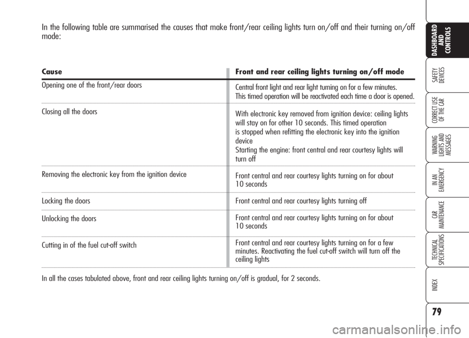
In the following table are summarised the causes that make front/rear ceiling lights turn on/off and their turning on/off
mode:
Cause
Opening one of the front/rear doors
Closing all the doors
Removing the electronic key from the ignition device
Locking the doors
Unlocking the doors
Cutting in of the fuel cut-off switch
Front and rear ceiling lights turning on/off mode
Central front light and rear light turning on for a few minutes.
This timed operation will be reactivated each time a door is opened.
With electronic key removed from ignition device: ceiling lights
will stay on for other 10 seconds. This timed operation
is stopped when refitting the electronic key into the ignition
device
Starting the engine: front central and rear courtesy lights will
turn off
Front central and rear courtesy lights turning on for about
10 seconds
Front central and rear courtesy lights turning off
Front central and rear courtesy lights turning on for about
10 seconds
Front central and rear courtesy lights turning on for a few
minutes. Reactivating the fuel cut-off switch will turn off the
ceiling lights
In all the cases tabulated above, front and rear ceiling lights turning on/off is gradual, for 2 seconds.
Page 82 of 299

DOOR PUDDLE LIGHTS
The door light will turn on when open-
ing the door regardless of the electron-
ic key position. It will stay on for about
3 minutes when the door is open, then
it will go off automatically.
80
SAFETY
DEVICES
WARNING
LIGHTS AND
MESSAGES
IN AN
EMERGENCY
CAR
MAINTENANCE
TECHNICAL
SPECIFICATIONS
INDEX
CORRECT USE
OF THE CAR
DASHBOARD
AND
CONTROLS
IMPORTANTLeaving inadvertently a
door open, the ceiling lights will turn off
automatically after a few minutes. To
turn them on again, open another door
or close and open again the same door.
Versions with sunroof
(where provided) fig. 60
Versions with sunroof are fitted with two
rear ceiling lights located above the rears
doors.
Press lens A-fig. 60to turn these
lights on/off.REAR CEILING LIGHT
Versions without sunroof
fig. 59
Press button:
A:to turn on/off the driver’s courtesy
light;
B:to turn on/off the passenger’s cour-
tesy light.
Closing the doors, the ceiling lights will
stay on for a few seconds, then they will
switch off automatically. Ceiling lights
will turn off when fitting the electronic
key into the ignition device.
A0E0094mfig. 59A0E0037mfig. 60
Page 83 of 299
81
SAFETY
DEVICES
WARNING
LIGHTS AND
MESSAGES
IN AN
EMERGENCY
CAR
MAINTENANCE
TECHNICAL
SPECIFICATIONS
INDEX
CORRECT USE
OF THE CAR
DASHBOARD
AND
CONTROLS
CONTROLS
POWER SUPPLY AND FUEL
CUT-OFF SWITCHES
The car is fitted with a safety switch that
in the event of a crash comes into op-
eration by cutting off fuel and turning
off the engine as a consequence.
Certain versions are equipped with an
additional safety switch that in the event
of a crash comes into operation by cut-
ting off the power supply.
These two safety switches therefore pre-
vent dangerous fuel leaks due to fuel
line cracking, and sparks or electric dis-
charges due to damaging or malfunc-
tioning of the electric components of the
car in the event of a crash.
IMPORTANTAfter a crash, remem-
ber to remove the key from the ignition
device to prevent battery run-down.
If, after a crash, you
smell fuel or see leaks
from the fuel system, do not
reset the switches to avoid
fire risk.
WARNING
If central door locking
has been activated
from inside the car and after a
crash the fuel cut-off switch
cannot activate automatic door
unlocking, it will not be pos-
sible to get into the car. In any
case, door opening from the
outside depends on door con-
ditions after the crash: if a
door is badly damaged it will
be impossible to open it. In this
event try to open one of the
other doors.
WARNING
Door unlocking in the event
of a crash
In the event of a crash that triggers the
fuel cut-off switch, the doors will unlock
automatically to enable getting into the
car and at the same time the passen-
ger’s compartment lights will turn on.
It is however always possible to open
the doors from the passenger’s com-
partment by means of the internal door
handles.
If, after a crash no fuel leaks or dam-
ages to the electric devices (e.g. head-
lights) are found and the car can be
started again, reset the fuel cut-off
switch and the power supply cut-off
switch (where provided). Follow the in-
structions given below.
Page 90 of 299
88
SAFETY
DEVICES
WARNING
LIGHTS AND
MESSAGES
IN AN
EMERGENCY
CAR
MAINTENANCE
TECHNICAL
SPECIFICATIONS
INDEX
CORRECT USE
OF THE CAR
DASHBOARD
AND
CONTROLS
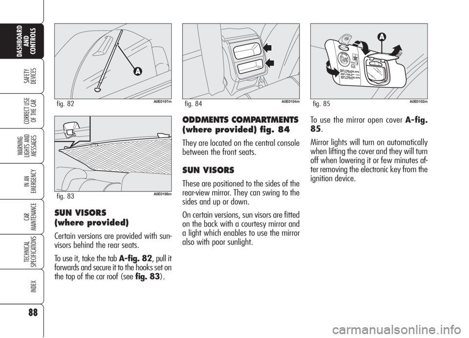
ODDMENTS COMPARTMENTS
(where provided) fig. 84
They are located on the central console
between the front seats.
SUN VISORS
These are positioned to the sides of the
rear-view mirror. They can swing to the
sides and up or down.
On certain versions, sun visors are fitted
on the back with a courtesy mirror and
a light which enables to use the mirror
also with poor sunlight.
A0E0154mfig. 84A0E0102mfig. 85
To use the mirror open cover A-fig.
85.
Mirror lights will turn on automatically
when lifting the cover and they will turn
off when lowering it or few minutes af-
ter removing the electronic key from the
ignition device.
SUN VISORS
(where provided)
Certain versions are provided with sun-
visors behind the rear seats.
To use it, take the tab A-fig. 82, pull it
forwards and secure it to the hooks set on
the top of the car roof (see fig. 83).
A0E0197mfig. 82
A0E0198mfig. 83
Page 91 of 299
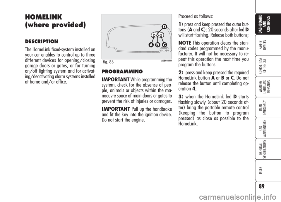
PROGRAMMING
IMPORTANTWhile programming the
system, check for the absence of peo-
ple, animals or objects within the ma-
noeuvre space of main doors or gates to
prevent the risk of injuries or damages.
IMPORTANTPull up the handbrake
and fit the key into the ignition device.
Do not start the engine.Proceed as follows:
1) press and keep pressed the outer but-
tons (AandC): 20 seconds after led D
will start flashing. Release both buttons;
NOTEThis operation clears the stan-
dard codes programmed by the manu-
facturer. It will not be necessary to re-
peat this operation the next time you
program the buttons.
2) press and keep pressed the required
HomeLink button AorBorC. Do not
release the button until completing op-
eration4;
3) when the HomeLink led Dstarts
flashing slowly (about 20 seconds af-
ter) bring the portable remote control
(keeping the button to program
pressed) as close as possible to the
HomeLink.
89
SAFETY
DEVICES
WARNING
LIGHTS AND
MESSAGES
IN AN
EMERGENCY
CAR
MAINTENANCE
TECHNICAL
SPECIFICATIONS
INDEX
CORRECT USE
OF THE CAR
DASHBOARD
AND
CONTROLS
HOMELINK
(where provided)
DESCRIPTION
The HomeLink fixed-system installed on
your car enables to control up to three
different devices for opening/closing
garage doors or gates, or for turning
on/off lighting system and for activat-
ing/deactivating alarm systems installed
at home and/or office.
A0E0311mfig. 86
Page 92 of 299

HOW TO USE THE
HOMELINK SYSTEM
The HomeLink remote control activates
the operation of the garage door mo-
tor or gate motor exactly as the portable
remote control. The car shall be within
the range of the motor and the key shall
be fitted into the ignition device.
Press the programmed button (AorB
orC). During signal transmission the led
Dwill stay on and the set system
(garage door, gate, etc.) will obey.
If the HomeLink system set as described
above does not work, this may be due
to the fact the original portable remote
control has an alternate code (see para-
graph "Synchronising alternate codes").
It is however always possible to use the
original portable remote control to op-
erate the system (garage door, gate,
etc.).
SYNCHRONISING
ALTERNATE CODES
To ascertain whether your garage door
motor or gate motor is provided with an
alternate code, proceed as follows:
consult the owner handbook provided
by the garage door motor's or gate mo-
tor's manufacturer;
the portable remote control seems to
have programmed HomeLink; HomeLink
however is not up to open or to close
the garage door or the gate;
press and keep pressed the programmed
button (AorBorC).
With an alternate code system, the led
Dblinks fast for short and then it stays
on glowing steadily for two seconds.
This sequence is repeated for 20 sec-
onds. The distance required between the
portable remote control and the Home-
Link depends on the system to be pro-
grammed (type of frequency of main
door, gate or other system).
IfDdoes not start to flash quickly try
again changing the distance between
HomeLink and portable remote control
(move them away slightly). If 20 sec-
onds later the led is still flashing slow-
ing, repeat the operation changing again
the distance between Homelink and re-
mote control.
4) the HomeLink led Dwill start blink-
ing, first slowly and then quickly. When
it starts flashing quickly, release both
buttons (HomeLink and portable remote
control).
90
SAFETY
DEVICES
WARNING
LIGHTS AND
MESSAGES
IN AN
EMERGENCY
CAR
MAINTENANCE
TECHNICAL
SPECIFICATIONS
INDEX
CORRECT USE
OF THE CAR
DASHBOARD
AND
CONTROLS
Page 93 of 299
Proceed as follows:
❒find the set-up button on the upper
side of the garage door/gate motor.
Colour and position may vary ac-
cording to the manufacturer (consult
the motor handbook);
❒press the motor set-up button (this
action will usually turn up the "set-
up" pilot light). After operation 2,
start to perform operation 3 within
30 seconds;
❒press the programmed button (Aor
BorC) and release it. Press again
the programmed button and then re-
lease it to end the operation. Certain
motors could require to repeat once
again the operation for concluding
the setting.
Now the motor should be up to recog-
nise the signal transmitted by HomeLink
and therefore to open/close the garage
door or the gate.
RE-PROGRAMMING ONE
SINGLE BUTTON
It is possible to programme another orig-
inal portable remote control on one
HomeLink button already programmed.
Previous programming will be cancelled.
IMPORTANTWhile programming the
system, check for the absence of peo-
ple, animals or objects within the ma-
noeuvre space of main doors or gates to
prevent the risk of injuries or damages.
IMPORTANTPull up the handbrake
and fit the key into the ignition device.
Do not start the engine.
Proceed as follows:
1) press and keep pressed the required
HomeLink button AorBorC. Do not
release the button until completing op-
eration3;
2) when the HomeLink led Dstarts
flashing slowly (about 20 seconds af-
ter) bring the portable remote control
(keeping the button to program
pressed) as close as possible to the
HomeLink. HomeLink can only work if the pro-
grammed alternate code is synchronised
with the system of the device (garage
door, gate, etc.).
IMPORTANTWhile synchronising the
system, check for the absence of peo-
ple, animals or objects within the ma-
noeuvre space of main doors or gates to
prevent the risk of injuries or damages.
IMPORTANTThe car shall be within
the range of the motor. Pull up the hand-
brake and fit the key into the ignition
device. Do not start the engine.
91
SAFETY
DEVICES
WARNING
LIGHTS AND
MESSAGES
IN AN
EMERGENCY
CAR
MAINTENANCE
TECHNICAL
SPECIFICATIONS
INDEX
CORRECT USE
OF THE CAR
DASHBOARD
AND
CONTROLS
Page 95 of 299

93
SAFETY
DEVICES
WARNING
LIGHTS AND
MESSAGES
IN AN
EMERGENCY
CAR
MAINTENANCE
TECHNICAL
SPECIFICATIONS
INDEX
CORRECT USE
OF THE CAR
DASHBOARD
AND
CONTROLS
SUNROOF
(where provided)
The sunroof consists of a moving pane
sliding horizontally and retractable.
When closed it enables sunlight to get
into the passenger compartment, where-
as when open it enables wide opening
of the whole glass sunroof surface.
The sunroof is provided with manually-
operated sun curtain with handle and air
vents.
Sunroof can only be operated when the
key is fitted into the ignition device.
Do not open the sunroof
if there is snow or ice on
it: it could be damaged.
IMPORTANTTop comfort position
with sunroof open is obtained by turn-
ing selector A-fig. 87to position.
Operating the selector it is possible to
open/close the sunroof in one of the fol-
lowing cases:
❒fitting the electronic key into the ig-
nition device;
❒in the first 2 minutes after removing
the key from the ignition device or up
to door opening.
Opening from outside the car
Press the electronic key button
Ëfor
over 2 seconds.
When leaving the car,
the ignition key should
be removed to prevent the
sunroof from being operated
inadvertently and harming
anyone remaining in the car.
Improper use of the sunroof
can be dangerous. Before and
during its operation ensure
that any passengers are not at
risk from the moving roof ei-
ther by personal objects get-
ting caught in the mechanism
or by being injured by it di-
rectly.
WARNING
C
A0E0238mfig. 87
SUNROOF OPENING
Opening from inside the car
Turn selector A-fig. 87, as shown by the
arrow. The sunroof will stop in position as
soon as the selector is released.