engine Alfa Romeo 159 2006 Owner handbook (in English)
[x] Cancel search | Manufacturer: ALFA ROMEO, Model Year: 2006, Model line: 159, Model: Alfa Romeo 159 2006Pages: 299, PDF Size: 4.64 MB
Page 175 of 299

173
SAFETY
DEVICES
IN AN
EMERGENCY
CAR
MAINTENANCE
TECHNICAL
SPECIFICATIONS
INDEX
CORRECT USE
OF THE CAR
DASHBOARD
AND
CONTROLS
WARNING
LIGHTS AND
MESSAGES
This cycle is performed only once when
the outside temperature read is lower
than or equal to 3°C and it can be re-
peated only when outside temperature
exceeds
6 °C and then falls down to 3 °C or be-
low.
IMPORTANTIn the event of outside
temperature sensor failure, the display
will show dashes instead of the value.PRE-HEATING
GLOW PLUGS
(diesel versions -
amber)
PRE-HEATING
GLOW PLUGS
FAILURE
(diesel
versions - amber)
Pre-heating glow plugs
Fitting the key into the ignition device
the warning light turns on and it will turn
off when glow plugs reach the preset
temperature. Start the engine immedi-
ately after warning light switching off.
IMPORTANTWith mild or hot ambi-
ent temperature, warning light stays on
for very short time.
m
POSSIBLE PRESENCE OF ICE
ON THE ROAD
When the outside temperature reaches
or falls below 3°C, the display will show
a warning message, symbol
√, and a
buzzer will sound to warn the driver of
the possible presence of ice on the road.
On certain versions, once the above
warning indication cycle is over or when
pressing briefly the button MENU:
– the displayed message goes off and
previously active screen is displayed
again;
– temperature indication stops flashing;
– symbol
√stays displayed at the bot-
tom right of the screen (until outside
temperature is lower than or equal to
6°C).
Page 176 of 299
174
SAFETY
DEVICES
IN AN
EMERGENCY
CAR
MAINTENANCE
TECHNICAL
SPECIFICATIONS
INDEX
CORRECT USE
OF THE CAR
DASHBOARD
AND
CONTROLS
WARNING
LIGHTS AND
MESSAGES
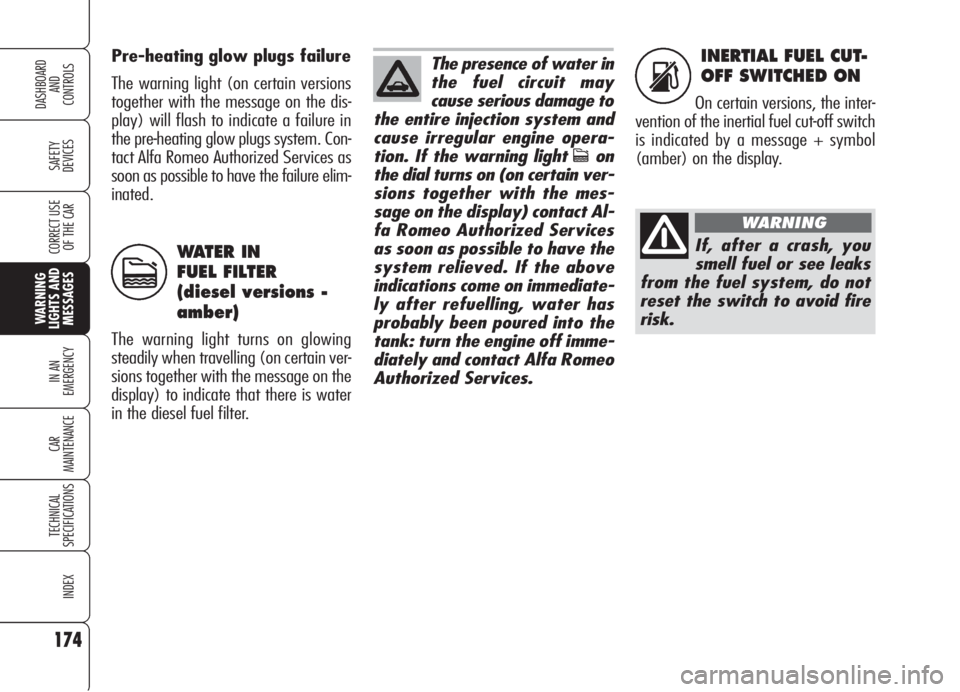
INERTIAL FUEL CUT-
OFF SWITCHED ON
On certain versions, the inter-
vention of the inertial fuel cut-off switch
is indicated by a message + symbol
(amber) on the display. Pre-heating glow plugs failure
The warning light (on certain versions
together with the message on the dis-
play) will flash to indicate a failure in
the pre-heating glow plugs system. Con-
tact Alfa Romeo Authorized Services as
soon as possible to have the failure elim-
inated.
WATER IN
FUEL FILTER
(diesel versions -
amber)
The warning light turns on glowing
steadily when travelling (on certain ver-
sions together with the message on the
display) to indicate that there is water
in the diesel fuel filter.
c
The presence of water in
the fuel circuit may
cause serious damage to
the entire injection system and
cause irregular engine opera-
tion. If the warning light
con
the dial turns on (on certain ver-
sions together with the mes-
sage on the display) contact Al-
fa Romeo Authorized Services
as soon as possible to have the
system relieved. If the above
indications come on immediate-
ly after refuelling, water has
probably been poured into the
tank: turn the engine off imme-
diately and contact Alfa Romeo
Authorized Services.
If, after a crash, you
smell fuel or see leaks
from the fuel system, do not
reset the switch to avoid fire
risk.
WARNING
s
Page 177 of 299
175
SAFETY
DEVICES
IN AN
EMERGENCY
CAR
MAINTENANCE
TECHNICAL
SPECIFICATIONS
INDEX
CORRECT USE
OF THE CAR
DASHBOARD
AND
CONTROLS
WARNING
LIGHTS AND
MESSAGES
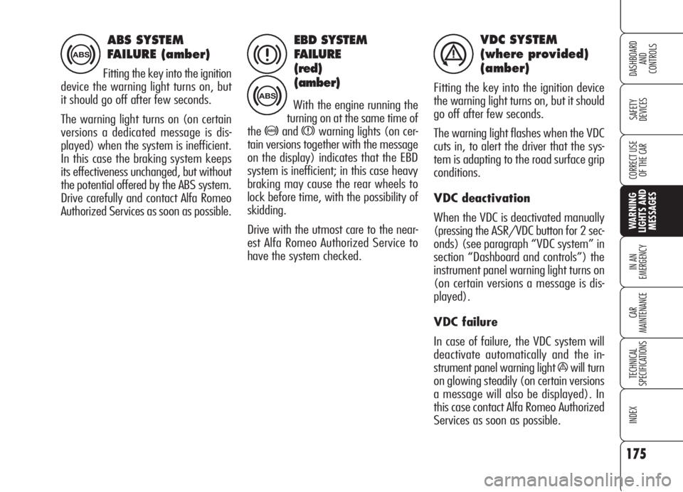
EBD SYSTEM
FAILURE
(red)
(amber)
With the engine running the
turning on at the same time of
the
>andxwarning lights (on cer-
tain versions together with the message
on the display) indicates that the EBD
system is inefficient; in this case heavy
braking may cause the rear wheels to
lock before time, with the possibility of
skidding.
Drive with the utmost care to the near-
est Alfa Romeo Authorized Service to
have the system checked.
VDC SYSTEM
(where provided)
(amber)
Fitting the key into the ignition device
the warning light turns on, but it should
go off after few seconds.
The warning light flashes when the VDC
cuts in, to alert the driver that the sys-
tem is adapting to the road surface grip
conditions.
VDC deactivation
When the VDC is deactivated manually
(pressing the ASR/VDC button for 2 sec-
onds) (see paragraph “VDC system” in
section “Dashboard and controls”) the
instrument panel warning light turns on
(on certain versions a message is dis-
played).
VDC failure
In case of failure, the VDC system will
deactivate automatically and the in-
strument panel warning light
áwill turn
on glowing steadily (on certain versions
a message will also be displayed). In
this case contact Alfa Romeo Authorized
Services as soon as possible.
ABS SYSTEM
FAILURE (amber)
Fitting the key into the ignition
device the warning light turns on, but
it should go off after few seconds.
The warning light turns on (on certain
versions a dedicated message is dis-
played) when the system is inefficient.
In this case the braking system keeps
its effectiveness unchanged, but without
the potential offered by the ABS system.
Drive carefully and contact Alfa Romeo
Authorized Services as soon as possible.
>
>
xá
Page 184 of 299
182
SAFETY
DEVICES
WARNING
LIGHTS AND
MESSAGES
CAR
MAINTENANCE
TECHNICAL
SPECIFICATIONS
INDEX
CORRECT USE
OF THE CAR
DASHBOARD
AND
CONTROLS
IN AN
EMERGENCY
JUMP STARTING
If the battery is flat, it is possible to start
the engine using an auxiliary battery
with the same capacity or a little high-
er than the flat one.
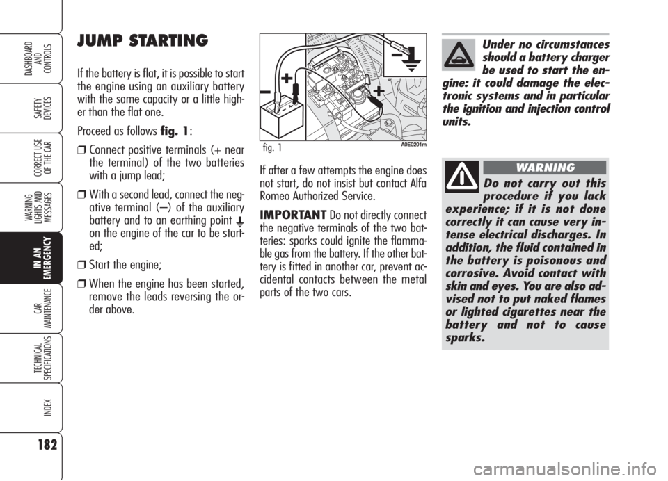
Proceed as follows fig. 1:
❒ Connect positive terminals (+ near
the terminal) of the two batteries
with a jump lead;
❒ With a second lead, connect the neg-
ative terminal (–) of the auxiliary
battery and to an earthing point
E
on the engine of the car to be start-
ed;
❒Start the engine;
❒When the engine has been started,
remove the leads reversing the or-
der above.If after a few attempts the engine does
not start, do not insist but contact Alfa
Romeo Authorized Service.
IMPORTANTDo not directly connect
the negative terminals of the two bat-
teries: sparks could ignite the flamma-
ble gas from the battery. If the other bat-
tery is fitted in another car, prevent ac-
cidental contacts between the metal
parts of the two cars.
Under no circumstances
should a battery charger
be used to start the en-
gine: it could damage the elec-
tronic systems and in particular
the ignition and injection control
units.
Do not carry out this
procedure if you lack
experience; if it is not done
correctly it can cause very in-
tense electrical discharges. In
addition, the fluid contained in
the battery is poisonous and
corrosive. Avoid contact with
skin and eyes. You are also ad-
vised not to put naked flames
or lighted cigarettes near the
battery and not to cause
sparks.
WARNING
A0E0201mfig. 1
Page 185 of 299
183
SAFETY
DEVICES
WARNING
LIGHTS AND
MESSAGES
CAR
MAINTENANCE
TECHNICAL
SPECIFICATIONS
INDEX
CORRECT USE
OF THE CAR
DASHBOARD
AND
CONTROLS
IN AN
EMERGENCY
IF A TYRE
IS PUNCTURED
For versions/markets where applicable,
the car can be equipped with the “Quick
tyre repair kit Fix&Go automatic“. Op-
erations required to change a wheel are
described in the following chapter.
As an alternative to the kit “Fix & Go
automatic”, the car can be provided (up-
on request) with space-saver spare
wheel or standard size spare wheel;
wheel changing and correct use of the
jack and space-saver spare wheel call for
some precautions as listed below.
BUMP STARTING
Never bump start the engine (by push-
ing, towing, or coasting downhill) as this
could cause fuel to flow into the catalytic
exhaust system and damage it beyond
repair.
Remember that the
brake booster and the
power steering system are not
operating until the engine is
started, a greater effort will
therefore be required to press
the brake pedal or turn the
steering wheel.
WARNING
Alert other drivers that
the car is stationary in
compliance with local regula-
tions: hazard warning lights,
warning triangle etc. Any pas-
sengers on board should leave
the car, especially if it is heav-
ily laden. Passengers should
stay away from oncoming
traffic while the wheel is be-
ing changed on. If the wheel is
being changed on a steep or
badly surfaced road, place the
wedges or other suitable ma-
terial under the wheel to stop
the car. Never start the engine
when the car is jacked up. If
you were towing a trailer, un-
couple the trailer before jack-
ing the car.
WARNING
Page 187 of 299
185
SAFETY
DEVICES
WARNING
LIGHTS AND
MESSAGES
CAR
MAINTENANCE
TECHNICAL
SPECIFICATIONS
INDEX
CORRECT USE
OF THE CAR
DASHBOARD
AND
CONTROLS
IN AN
EMERGENCY
Please note:
❒the jack weight is 1.76 kg;
❒the jack requires no adjustment;
❒the jack cannot be repaired. If it
breaks it must be replaced with a
new jack;
❒no tool other than its cranking device
may be fitted on the jack.To change a wheel proceed as follows:
❒Stop the car in a position that is not
dangerous for oncoming traffic where
you can change the wheel safely. The
ground should be flat and adequate-
ly firm;
❒Turn the engine off, pull up the hand-
brake and engage first gear or re-
verse;
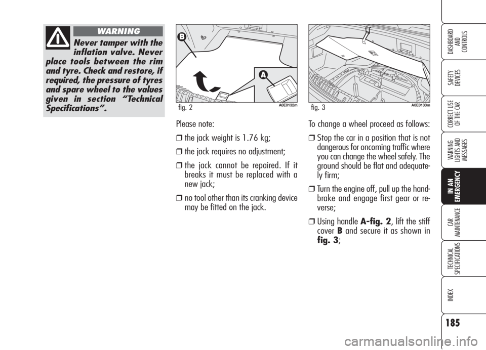
❒Using handle A-fig. 2, lift the stiff
coverBand secure it as shown in
fig. 3;
Never tamper with the
inflation valve. Never
place tools between the rim
and tyre. Check and restore, if
required, the pressure of tyres
and spare wheel to the values
given in section “Technical
Specifications”.
WARNING
A0E0132mfig. 2A0E0133mfig. 3
Page 195 of 299

193
SAFETY
DEVICES
WARNING
LIGHTS AND
MESSAGES
CAR
MAINTENANCE
TECHNICAL
SPECIFICATIONS
INDEX
CORRECT USE
OF THE CAR
DASHBOARD
AND
CONTROLS
IN AN
EMERGENCY
❒after reaching the tyre pressure spec-
ified in paragraph “Wheels” in sec-
tion “Technical Specifications”, start
driving immediately;
❒if after 5 minutes it is still impossi-
ble to reach at least 1.5 bar, disen-
gage compressor from valve and cur-
rent outlet, then move the car forth
for approx. 10 metres in order to dis-
tribute the sealing fluid inside the tyre
evenly, then repeat the inflation op-
eration;
❒If after this operation it is still im-
possible after 5 minutes to reach at
least 1.8 bar, do start driving since
the tyre is excessively damaged and
the quick tyre repair kit cannot guar-
antee suitable sealing, contact Alfa
Romeo Authorized Services;
❒make sure the compressor switch A-
fig. 19is set to 0(off), start the
engine and fit plug A-fig. 20into
the outlet/cigar lighter on the front
console and then turn on the com-
pressor by setting switch A-fig. 19
toI(on);
❒Inflate the tyre to the pressure speci-
fied in paragraph “Wheels” in section
“Technical Specifications”. Check tyre
pressure on gauge B-fig. 19 with
compressor off to obtain precise read-
ing;
A0E0213mfig. 19A0E0217mfig. 20Apply the sticker in a
visible position for the
driver to indicate that the tyre
has been treated with the
quick tyre repair kit. Drive
carefully especially when cor-
nering and do not exceed 80
km/h. Avoid heavy braking
and accelerating.
WARNING
Page 196 of 299

194
SAFETY
DEVICES
WARNING
LIGHTS AND
MESSAGES
CAR
MAINTENANCE
TECHNICAL
SPECIFICATIONS
INDEX
CORRECT USE
OF THE CAR
DASHBOARD
AND
CONTROLS
IN AN
EMERGENCY
You shall absolutely
communicate that the
tyre has been repaired with
the quick tyre repair kit. Hand
the instruction brochure to the
personnel charged with treat-
ing the tyre repaired with the
kit.
WARNING
A0E0215mfig. 21
A0E0216mfig. 22
CHECKING AND RESTORING
PRESSURE ONLY
The compressor can be also used just for
restoring pressure. Disconnect the quick
connectionA-fig. 21and connect it
directly to the tyre valve fig. 22; in this
way the cylinder is not connected to
compressor and the sealing fluid will not
flow into the tyre.
If pressure falls below
1.8 bar, stop the car
since the tyre is excessively
damaged and the quick tyre
repair kit Fix & Go automatic
cannot guarantee suitable
sealing, contact Alfa Romeo
Authorized Services.
WARNING
❒after driving for about 10 minutes
stop and check again the tyre pres-
sure;pull up the handbrake;❒if at least 1.8 bar pressure is read, re-
store proper pressure (with engine
running and handbrake on) and
restart;
❒drive with the utmost care to the
nearest Alfa Romeo Authorized
Service.
Page 216 of 299

214
SAFETY
DEVICES
WARNING
LIGHTS AND
MESSAGES
CAR
MAINTENANCE
TECHNICAL
SPECIFICATIONS
INDEX
CORRECT USE
OF THE CAR
DASHBOARD
AND
CONTROLS
IN AN
EMERGENCY
FUSE SUMMARY TABLE
LIGTHS FUSE AMPERE FIGURE
Right main beam headlight F14 10 60
Left main beam headlight F15 10 60
Right dipped beam headlight F12 15 56
Left dipped beam headlight F13 15 56
Front fog light F30 15 60
Reversing light F35 7.5 56
Third brake light F37 10 56
Front/rear ceiling light F39 10 56
Front ceiling light F49 7.5 56
Direction indicators F53 10 56
Hazard lights F53 10 56
USERS FUSE AMPERE FIGURE
Engine compartment control unit F70 (MEGA-FUSE) 150 58
Instrument panel control unit F71 70 58
Fuel pre-heating unit (diesel versions) F73 60 58
Boot control unit F01 (MAXI-FUSE) 70 60
Instrument panel control unit F01 (MAXI-FUSE) 70 60
Page 217 of 299
215
SAFETY
DEVICES
WARNING
LIGHTS AND
MESSAGES
CAR
MAINTENANCE
TECHNICAL
SPECIFICATIONS
INDEX
CORRECT USE
OF THE CAR
DASHBOARD
AND
CONTROLS
IN AN
EMERGENCY
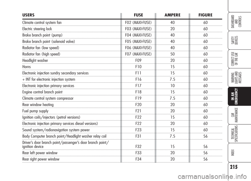
USERS FUSE AMPERE FIGURE
Climate control system fan F02 (MAXI-FUSE) 40 60
Electric steering lock F03 (MAXI-FUSE) 20 60
Brake branch point (pump) F04 (MAXI-FUSE) 40 60
Brake branch point (solenoid valve) F05 (MAXI-FUSE) 40 60
Radiator fan (low speed) F06 (MAXI-FUSE) 40 60
Radiator fan (high speed) F07 (MAXI-FUSE) 50 60
Headlight washer F09 20 60
Horns F10 15 60
Electronic injection sundry secondary services F11 15 60
+ INT for electronic injection system F16 7.5 60
Electronic injection primary services F17 10 60
Engine control branch point F18 15 60
Climate control system compressor F19 7.5 60
Rear window heating F20 20 60
Fuel pump supply F21 20 60
Ignition coils/injectors (petrol versions) F22 15 60
Electronic injection primary services diesel versions) F22 20 60
Sound system/radionavigation system power F23 15 60
Body Computer branch point/Headlight washer relay coil F31 7.5 56
Driver’s door branch point/passenger’s door branch point/
ignition device F32 15 56
Rear left power window F33 20 56
Rear right power window F34 20 56