alarm Alfa Romeo 159 2008 Owner handbook (in English)
[x] Cancel search | Manufacturer: ALFA ROMEO, Model Year: 2008, Model line: 159, Model: Alfa Romeo 159 2008Pages: 303, PDF Size: 5.18 MB
Page 8 of 303
6
SAFETY
DEVICES
WARNING
LIGHTS AND
MESSAGES
IN AN
EMERGENCY
CAR
MAINTENANCE
TECHNICAL
SPECIFICATIONS
INDEX
CORRECT USE
OF THE CAR
DASHBOARD
AND
CONTROLS
D D
A A
S S
H H
B B
O O
A A
R R
D D
A A
N N
D D
C C
O O
N N
T T
R R
O O
L L
S S
CRUISE CONTROL .............................................. 76
CEILING LIGHTS ................................................. 78
CONTROLS ........................................................ 81
INTERIOR FITTINGS............................................. 83
SUNROOF ......................................................... 93
DOORS ............................................................ 96
POWER WINDOWS ............................................ 99
BOOT ............................................................... 101
BONNET............................................................ 105
ROOF RACK/SKI RACK ....................................... 106
HEADLIGHTS...................................................... 106
ABS SYSTEM .................................................... 108
VDC SYSTEM .................................................... 110
EOBD SYSTEM .................................................. 115
SOUND SYSTEM PRESETTING .............................. 116
ACCESSORIES PURCHASED BY THE OWNER .......... 117
INSTALLATION OF ELECTRIC/ELECTRONIC DEVICES .. 117
PARKING SENSORS ............................................ 118
TYRE PRESSURE MONITORING SYSTEM
(T.P.M.S.) ......................................................... 122
AT THE FILLING STATION ..................................... 125
PROTECTING THE ENVIRONMENT ......................... 127 DASHBOARD...................................................... 7
INSTRUMENT PANEL .......................................... 8
SYMBOLS ........................................................ 10
ALFA ROMEO CODE SYSTEM ................................ 10
ELECTRONIC KEY ............................................... 12
ALARM ............................................................ 17
IGNITION DEVICE................................................ 19
INSTRUMENTS ................................................... 21
MULTIFUNCTION DISPLAY .................................... 25
RECONFIGURABLE MULTIFUNCTION DISPLAY .......... 30
SEATS .............................................................. 45
HEAD RESTRAINTS.............................................. 48
STEERING WHEEL .............................................. 49
REARVIEW MIRRORS .......................................... 50
CLIMATE CONTROL SYSTEM ................................ 53
MANUAL CLIMATE CONTROL SYSTEM ................... 55
AUTOMATIC TWO-/THREE-ZONE
CLIMATE CONTROL SYSTEM ................................ 58
ADDITIONAL HEATER .......................................... 69
EXTERNAL LIGHTS .............................................. 70
WINDOW WASHING .......................................... 73
Page 14 of 303
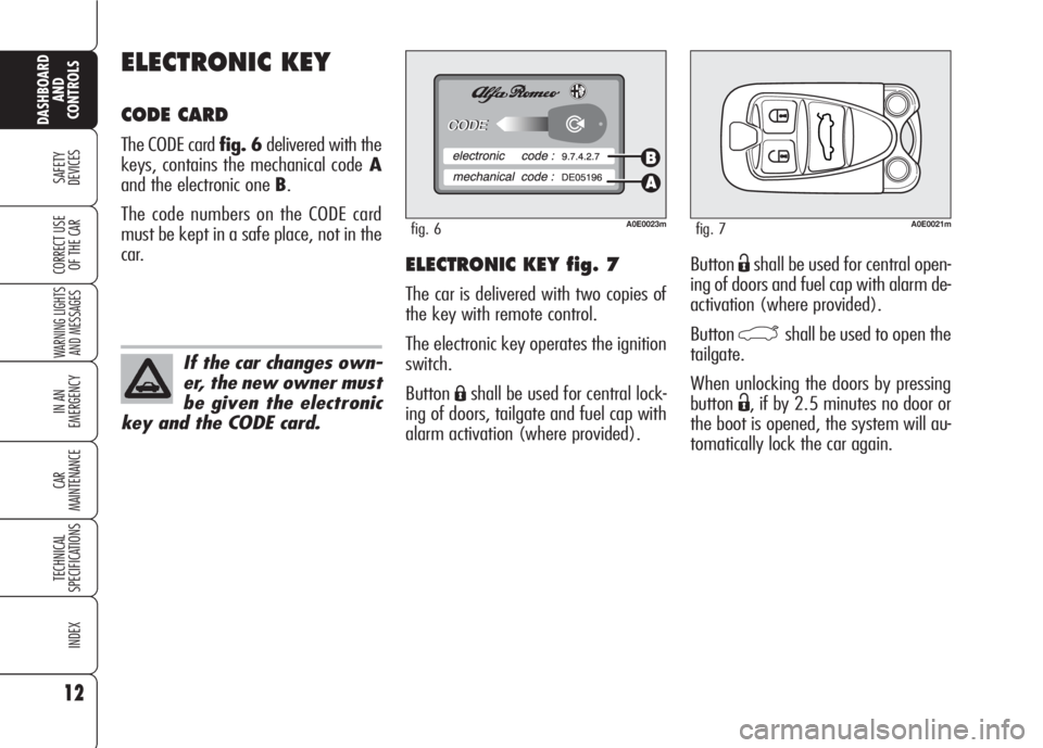
ButtonËshall be used for central open-
ing of doors and fuel cap with alarm de-
activation (where provided).
Button
`shall be used to open the
tailgate.
When unlocking the doors by pressing
button
Ë, if by 2.5 minutes no door or
the boot is opened, the system will au-
tomatically lock the car again.
ELECTRONIC KEY fig. 7
The car is delivered with two copies of
the key with remote control.
The electronic key operates the ignition
switch.
Button
Áshall be used for central lock-
ing of doors, tailgate and fuel cap with
alarm activation (where provided).
ELECTRONIC KEY
CODE CARD
The CODE card fig. 6delivered with the
keys, contains the mechanical codeA
and the electronic one B.
The code numbers on the CODE card
must be kept in a safe place, not in the
car.
12
SAFETY
DEVICES
WARNING LIGHTS
AND MESSAGES
IN AN
EMERGENCY
CAR
MAINTENANCE
TECHNICAL
SPECIFICATIONS
INDEX
DASHBOARD
AND
CONTROLS
CORRECT USE
OF THE CAR
A0E0023mfig. 6
If the car changes own-
er, the new owner must
be given the electronic
key and the CODE card.
A0E0021mfig. 7
Page 19 of 303
17
SAFETY
DEVICES
WARNING LIGHTS
AND MESSAGES
IN AN
EMERGENCY
CAR
MAINTENANCE
TECHNICAL
SPECIFICATIONS
INDEX
DASHBOARD
AND
CONTROLS
CORRECT USE
OF THE CAR
Depending on the markets, the trigger-
ing of the alarm will activate the siren
and the hazard warning lights (for about
26 seconds). The methods of operation
and the number of cycles may vary de-
pending on the versions/markets.
A maximum number of sound/sight cy-
cles is however envisaged. Once the
alarm cycle is over, the system will re-
store its normal operation.
IMPORTANTCentral door unlocking
by the emergency electronic key will not
deactivate the alarm, therefore with
alarm on the siren will activate when
opening one of the doors or the boot.
To deactivate the siren see paragraph
“How to deactivate the alarm”.
IMPORTANTThe engine immobiliser
function is guaranteed by the Alfa
Romeo CODE system, which is auto-
matically activated when the electronic
key is removed from the ignition device.
HOW TO ACTIVATE
THE ALARM
With the doors, bonnet and boot shut
and electronic key removed from igni-
tion switch, point the electronic key in
the direction of the car, then press and
release the button
Á.
With the exception of certain markets,
the system sounds a “beep” and the
doors are locked.
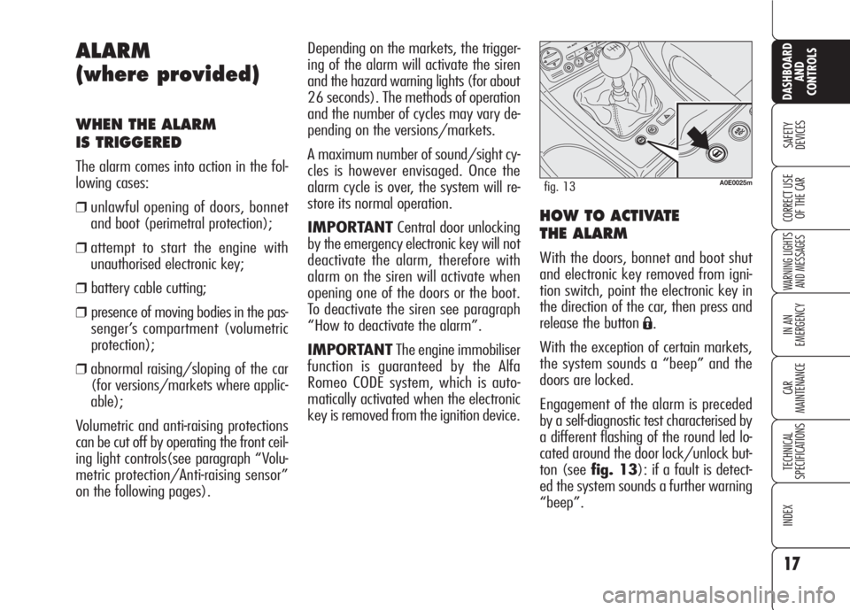
Engagement of the alarm is preceded
by a self-diagnostic test characterised by
a different flashing of the round led lo-
cated around the door lock/unlock but-
ton (see fig. 13): if a fault is detect-
ed the system sounds a further warning
“beep”.
ALARM
(where provided)
WHEN THE ALARM
IS TRIGGERED
The alarm comes into action in the fol-
lowing cases:
❒unlawful opening of doors, bonnet
and boot (perimetral protection);
❒attempt to start the engine with
unauthorised electronic key;
❒ battery cable cutting;
❒ presence of moving bodies in the pas-
senger’s compartment (volumetric
protection);
❒abnormal raising/sloping of the car
(for versions/markets where applic-
able);
Volumetric and anti-raising protections
can be cut off by operating the front ceil-
ing light controls(see paragraph “Volu-
metric protection/Anti-raising sensor”
on the following pages).
A0E0025mfig. 13
Page 20 of 303
HOW TO DEACTIVATE
THE ALARM
Press button Ë. The system will react as
follows (with the exception of certain
markets):
❒two brief flashes of the direction in-
dicators;
❒two brief “beeps”;
❒door unlocking.
The alarm can be deactivated by fitting
the electronic key into the ignition
switch.
IMPORTANTOn certain versions any
attempt to break in detected by the sys-
tem will be indicated by a warning mes-
sage on the instrument panel display
when fitting the electronic key into the
ignition switch.VOLUMETRIC PROTECTION/
ANTI-RAISING SENSORS
To make sure that the protection sensors
are working properly, check that win-
dows and sunroof (where provided) are
shut.
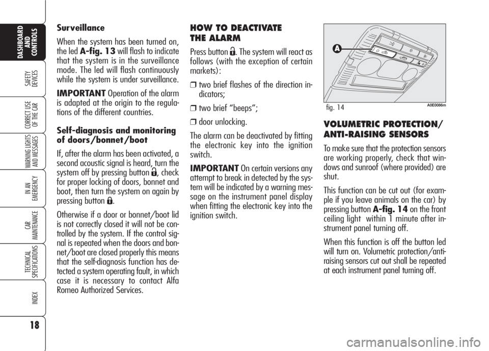
This function can be cut out (for exam-
ple if you leave animals on the car) by
pressing button A-fig. 14on the front
ceiling light within 1 minute after in-
strument panel turning off.
When this function is off the button led
will turn on. Volumetric protection/anti-
raising sensors cut out shall be repeated
at each instrument panel turning off. Surveillance
When the system has been turned on,
the led A-fig. 13will flash to indicate
that the system is in the surveillance
mode. The led will flash continuously
while the system is under surveillance.
IMPORTANTOperation of the alarm
is adapted at the origin to the regula-
tions of the different countries.
Self-diagnosis and monitoring
of doors/bonnet/boot
If, after the alarm has been activated, a
second acoustic signal is heard, turn the
system off by pressing button
Ë, check
for proper locking of doors, bonnet and
boot, then turn the system on again by
pressing button
Á.
Otherwise if a door or bonnet/boot lid
is not correctly closed it will not be con-
trolled by the system. If the control sig-
nal is repeated when the doors and bon-
net/boot are closed properly this means
that the self-diagnosis function has de-
tected a system operating fault, in which
case it is necessary to contact Alfa
Romeo Authorized Services.
18
SAFETY
DEVICES
WARNING LIGHTS
AND MESSAGES
IN AN
EMERGENCY
CAR
MAINTENANCE
TECHNICAL
SPECIFICATIONS
INDEX
DASHBOARD
AND
CONTROLS
CORRECT USE
OF THE CAR
A0E0086mfig. 14
Page 21 of 303
19
SAFETY
DEVICES
WARNING LIGHTS
AND MESSAGES
IN AN
EMERGENCY
CAR
MAINTENANCE
TECHNICAL
SPECIFICATIONS
INDEX
DASHBOARD
AND
CONTROLS
CORRECT USE
OF THE CAR
IGNITION DEVICE
The ignition device is located on the
dashboard and it consists of the follow-
ing:
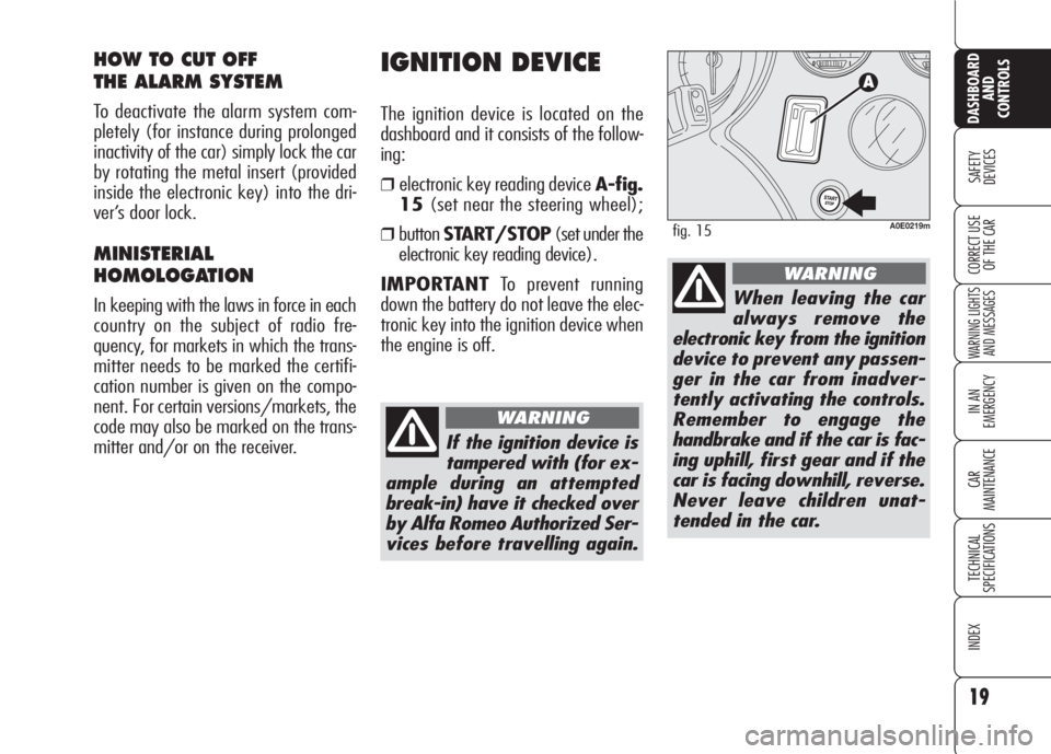
❒electronic key reading device A-fig.
15(set near the steering wheel);
❒buttonSTART/STOP(set under the
electronic key reading device).
IMPORTANTTo prevent running
down the battery do not leave the elec-
tronic key into the ignition device when
the engine is off.
HOW TO CUT OFF
THE ALARM SYSTEM
To deactivate the alarm system com-
pletely (for instance during prolonged
inactivity of the car) simply lock the car
by rotating the metal insert (provided
inside the electronic key) into the dri-
ver’s door lock.
MINISTERIAL
HOMOLOGATION
In keeping with the laws in force in each
country on the subject of radio fre-
quency, for markets in which the trans-
mitter needs to be marked the certifi-
cation number is given on the compo-
nent. For certain versions/markets, the
code may also be marked on the trans-
mitter and/or on the receiver.
A0E0219mfig. 15
If the ignition device is
tampered with (for ex-
ample during an attempted
break-in) have it checked over
by Alfa Romeo Authorized Ser-
vices before travelling again.
WARNING
When leaving the car
always remove the
electronic key from the ignition
device to prevent any passen-
ger in the car from inadver-
tently activating the controls.
Remember to engage the
handbrake and if the car is fac-
ing uphill, first gear and if the
car is facing downhill, reverse.
Never leave children unat-
tended in the car.
WARNING
Page 91 of 303
PROGRAMMING
IMPORTANTWhile programming the
system, check for the absence of peo-
ple, animals or objects within the ma-
noeuvre space of main doors or gates to
prevent the risk of injuries or damages.
IMPORTANTPull up the handbrake
and fit the key into the ignition device.
Do not start the engine.Proceed as follows:
1) press and keep pressed the outer but-
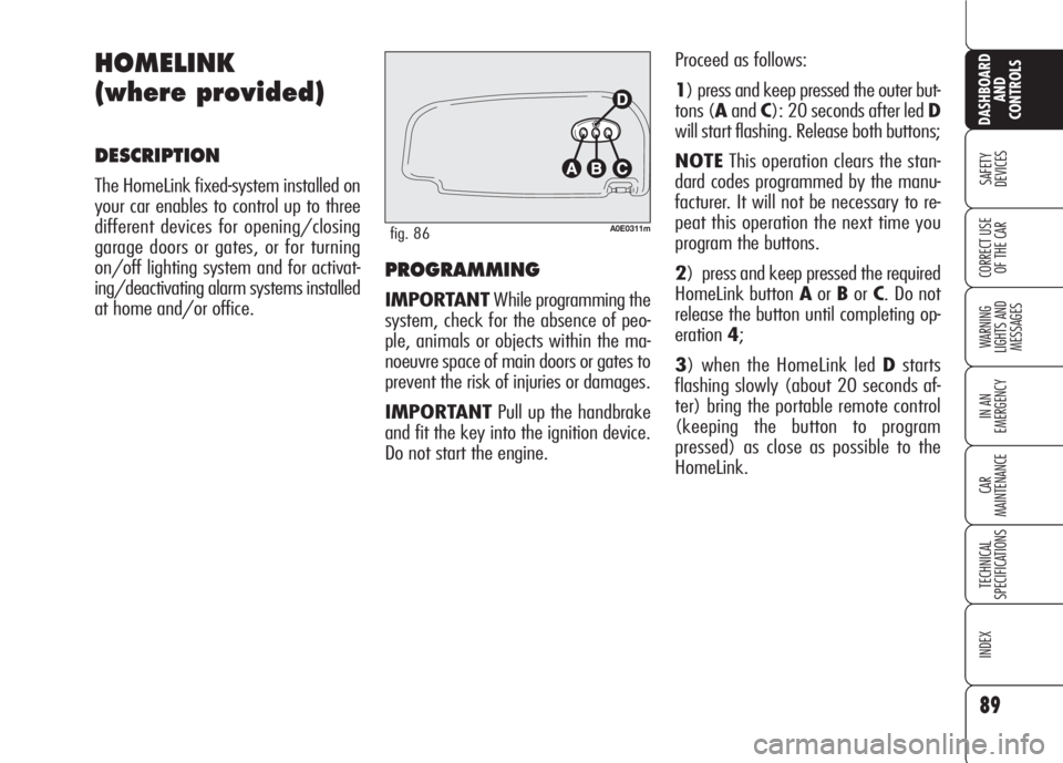
tons (AandC): 20 seconds after led D
will start flashing. Release both buttons;
NOTEThis operation clears the stan-
dard codes programmed by the manu-
facturer. It will not be necessary to re-
peat this operation the next time you
program the buttons.
2) press and keep pressed the required
HomeLink button AorBorC. Do not
release the button until completing op-
eration4;
3) when the HomeLink led Dstarts
flashing slowly (about 20 seconds af-
ter) bring the portable remote control
(keeping the button to program
pressed) as close as possible to the
HomeLink.
89
SAFETY
DEVICES
WARNING
LIGHTS AND
MESSAGES
IN AN
EMERGENCY
CAR
MAINTENANCE
TECHNICAL
SPECIFICATIONS
INDEX
CORRECT USE
OF THE CAR
DASHBOARD
AND
CONTROLS
HOMELINK
(where provided)
DESCRIPTION
The HomeLink fixed-system installed on
your car enables to control up to three
different devices for opening/closing
garage doors or gates, or for turning
on/off lighting system and for activat-
ing/deactivating alarm systems installed
at home and/or office.
A0E0311mfig. 86
Page 104 of 303
102
SAFETY
DEVICES
WARNING
LIGHTS AND
MESSAGES
IN AN
EMERGENCY
CAR
MAINTENANCE
TECHNICAL
SPECIFICATIONS
INDEX
CORRECT USE
OF THE CAR
DASHBOARD
AND
CONTROLS
OPENING BY REMOTE
CONTROL
Press the electronic key button `.
Opening is indicated by double flashing
of direction indicators.
Opening the boot with alarm (where
provided) on will cause the following:
❒volumetric protection deactivation;
❒anti-raising protection deactivation;
❒tailgate monitoring sensor.
Re-closing the tailgate will restore all the
above functions and direction indicators
will turn on for about 1 second. Emergency opening of the
boot from the passenger
compartment (foreseen only
on the 3-volume saloon
version)
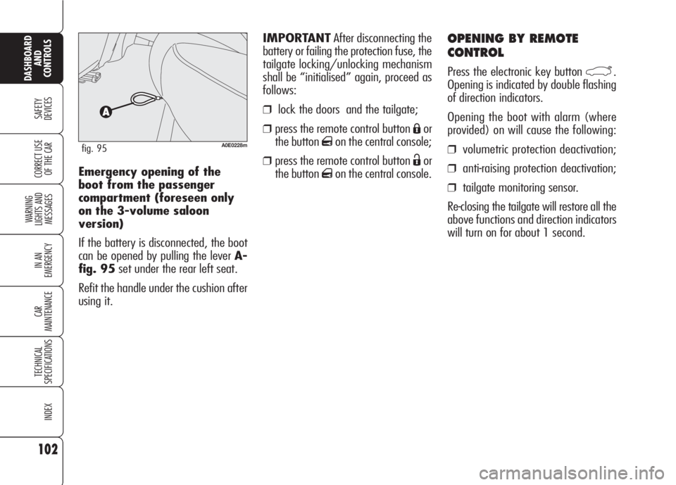
If the battery is disconnected, the boot
can be opened by pulling the lever A-
fig. 95set under the rear left seat.
Refit the handle under the cushion after
using it.
A0E0228mfig. 95
IMPORTANTAfter disconnecting the
battery or failing the protection fuse, the
tailgate locking/unlocking mechanism
shall be “initialised” again, proceed as
follows:
❒lock the doors and the tailgate;
❒press the remote control button Áor
the button
qon the central console;
❒press the remote control button Ëor
the button
qon the central console.
Page 119 of 303
117
SAFETY
DEVICES
WARNING
LIGHTS AND
MESSAGES
IN AN
EMERGENCY
CAR
MAINTENANCE
TECHNICAL
SPECIFICATIONS
INDEX
CORRECT USE
OF THE CAR
DASHBOARD
AND
CONTROLS
RADIO TRANSMITTERS AND
CELLULAR TELEPHONES
Mobile phones and other radio trans-
ceiver equipment (e.g.: HAM radio sys-
tems and the like) shall not be used in-
side the car unless a separate aerial is
mounted.
IMPORTANTThe use of mobile
phones, HAM radio systems or other
similar devices inside the passenger
compartment (without separate aerial)
may cause electronic systems equipping
the car to malfunction. This could com-
promise safety in addition to constitut-
ing a potential hazard for the passen-
gers.
In addition, transmission and reception
of these devices may be affected by the
shielding effect of the car body.
As concerns the use of mobile phones
(GSM, GPRS, UMTS) with homologa-
tion , keep strictly to the mobile
phone manufacturer’s specifications.
ACCESSORIES
PURCHASED
BY THE OWNER
If after buying the car, you decide to in-
stall electrical accessories that require a
permanent electric supply (alarm, satel-
lite antitheft system, etc.) or accessories
that in any case burden the electric sup-
ply, contact Alfa Romeo Authorized Ser-
vices, whose qualified personnel, besides
suggesting the most suitable devices be-
longing to Lineaccessori Alfa Romeo, will
also evaluate the overall electric absorp-
tion, checking whether the car’s electric
system is able to withstand the load re-
quired, or whether it needs to be inte-
grated with a more powerful battery.
Take care when fitting
additional spoilers, al-
loy rims and non-standard
wheel caps: they might reduce
ventilation of the brakes, thus
their efficiency, during abrupt
and repeated braking, or long
downhill slopes. Make sure
that nothing (mats, etc.) gets
in the way of the pedals when
they are pushed down.
WARNING
INSTALLATION OF
ELECTRIC/ELECTRONIC
DEVICES
Electric/electronic devices installed af-
ter buying the car or in aftermarket shall
bear the and marking:
Fiat Auto S.p.A. authorizes the installa-
tion of transceivers provided that instal-
lation is carried out at a specialized
shop, workmanlike performed and in
compliance with manufacturer’s speci-
fications.
IMPORTANTInstallation of devices
resulting in modifications of car charac-
teristics may cause driving license seiz-
ing by traffic agents and also the lapse
of the warranty as concerns defects due
to the abovementioned modification or
traceable back to it directly or indirectly.
Fiat Auto S.p.A. declines all responsibil-
ity for damages caused by the installa-
tion of non-genuine accessories or not
recommended by Fiat Auto S.p.A. and
installed not in compliance with the spec-
ified requirements.
Page 120 of 303
118
SAFETY
DEVICES
WARNING
LIGHTS AND
MESSAGES
IN AN
EMERGENCY
CAR
MAINTENANCE
TECHNICAL
SPECIFICATIONS
INDEX
CORRECT USE
OF THE CAR
DASHBOARD
AND
CONTROLS
PARKING SENSORS
(where provided)
Parking sensors inform the driver about
the presence of obstacles behind the car
(versions fitted with 4 rear sensors) or
behind and in front of the car (versions
fitted with 4 rear sensors and 4 front
sensors).
This system is therefore an aid for the
driver when parking the car since it de-
tects obstacles out of the driver’s sight
range.
The presence and the distance from the
car of an obstacle is indicated by a warn-
ing buzzer - as the distance from the ob-
stacle decreases, the acoustic alarm be-
comes more frequent - and, only on cer-
tain versions, by an image on the dis-
play (see paragraph “Indications on the
display).
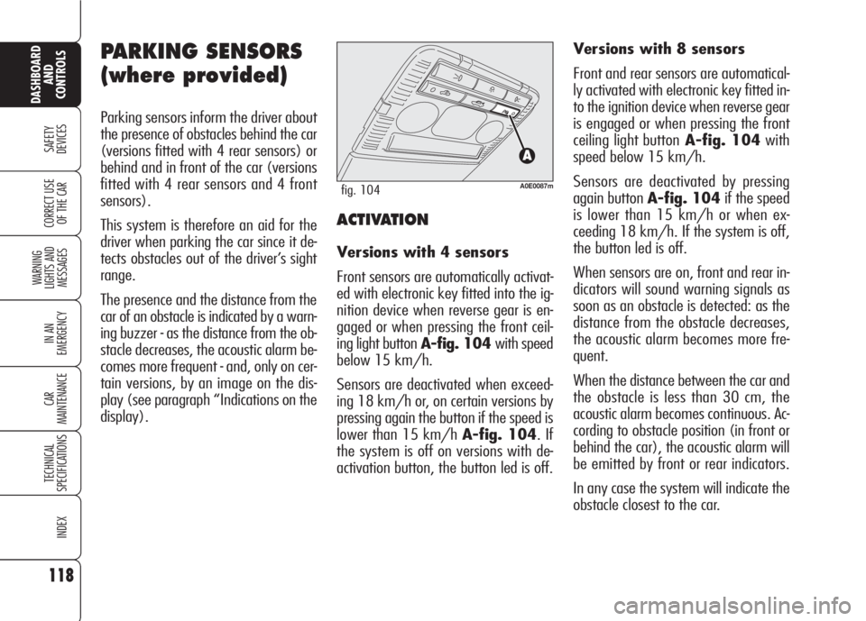
A0E0087mfig. 104
ACTIVATION
Versions with 4 sensors
Front sensors are automatically activat-
ed with electronic key fitted into the ig-
nition device when reverse gear is en-
gaged or when pressing the front ceil-
ing light button A-fig. 104 with speed
below 15 km/h.
Sensors are deactivated when exceed-
ing 18 km/h or, on certain versions by
pressing again the button if the speed is
lower than 15 km/h A-fig. 104. If
the system is off on versions with de-
activation button, the button led is off.Versions with 8 sensors
Front and rear sensors are automatical-
ly activated with electronic key fitted in-
to the ignition device when reverse gear
is engaged or when pressing the front
ceiling light buttonA-fig. 104with
speed below 15 km/h.
Sensors are deactivated by pressing
again button A-fig. 104if the speed
is lower than 15 km/h or when ex-
ceeding 18 km/h. If the system is off,
the button led is off.
When sensors are on, front and rear in-
dicators will sound warning signals as
soon as an obstacle is detected: as the
distance from the obstacle decreases,
the acoustic alarm becomes more fre-
quent.
When the distance between the car and
the obstacle is less than 30 cm, the
acoustic alarm becomes continuous. Ac-
cording to obstacle position (in front or
behind the car), the acoustic alarm will
be emitted by front or rear indicators.
In any case the system will indicate the
obstacle closest to the car.
Page 121 of 303
119
SAFETY
DEVICES
WARNING
LIGHTS AND
MESSAGES
IN AN
EMERGENCY
CAR
MAINTENANCE
TECHNICAL
SPECIFICATIONS
INDEX
CORRECT USE
OF THE CAR
DASHBOARD
AND
CONTROLS
The acoustic alarm will stop immediately
as distance raises. The acoustic alarm is
constant if the distance measured by
central sensors is unvaried, whereas if
this situation takes place for side sen-
sors the acoustic alarm is muted after
about 3 seconds to prevent sound indi-
cations when performing manoeuvres
near walls.
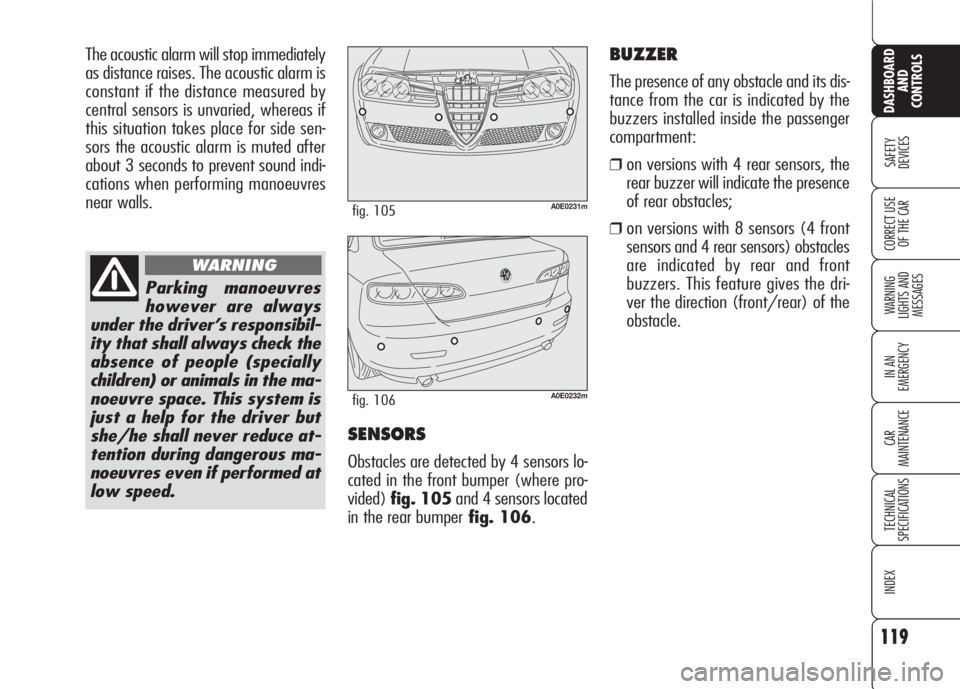
SENSORS
Obstacles are detected by 4 sensors lo-
cated in the front bumper (where pro-
vided)fig. 105and 4 sensors located
in the rear bumperfig. 106.
Parking manoeuvres
however are always
under the driver’s responsibil-
ity that shall always check the
absence of people (specially
children) or animals in the ma-
noeuvre space. This system is
just a help for the driver but
she/he shall never reduce at-
tention during dangerous ma-
noeuvres even if performed at
low speed.
WARNING
A0E0231mfig. 105
A0E0232mfig. 106
BUZZER
The presence of any obstacle and its dis-
tance from the car is indicated by the
buzzers installed inside the passenger
compartment:
❒on versions with 4 rear sensors, the
rear buzzer will indicate the presence
of rear obstacles;
❒on versions with 8 sensors (4 front
sensors and 4 rear sensors) obstacles
are indicated by rear and front
buzzers. This feature gives the dri-
ver the direction (front/rear) of the
obstacle.