bonnet Alfa Romeo 159 2008 Owner handbook (in English)
[x] Cancel search | Manufacturer: ALFA ROMEO, Model Year: 2008, Model line: 159, Model: Alfa Romeo 159 2008Pages: 303, PDF Size: 5.18 MB
Page 8 of 303
6
SAFETY
DEVICES
WARNING
LIGHTS AND
MESSAGES
IN AN
EMERGENCY
CAR
MAINTENANCE
TECHNICAL
SPECIFICATIONS
INDEX
CORRECT USE
OF THE CAR
DASHBOARD
AND
CONTROLS
D D
A A
S S
H H
B B
O O
A A
R R
D D
A A
N N
D D
C C
O O
N N
T T
R R
O O
L L
S S
CRUISE CONTROL .............................................. 76
CEILING LIGHTS ................................................. 78
CONTROLS ........................................................ 81
INTERIOR FITTINGS............................................. 83
SUNROOF ......................................................... 93
DOORS ............................................................ 96
POWER WINDOWS ............................................ 99
BOOT ............................................................... 101
BONNET............................................................ 105
ROOF RACK/SKI RACK ....................................... 106
HEADLIGHTS...................................................... 106
ABS SYSTEM .................................................... 108
VDC SYSTEM .................................................... 110
EOBD SYSTEM .................................................. 115
SOUND SYSTEM PRESETTING .............................. 116
ACCESSORIES PURCHASED BY THE OWNER .......... 117
INSTALLATION OF ELECTRIC/ELECTRONIC DEVICES .. 117
PARKING SENSORS ............................................ 118
TYRE PRESSURE MONITORING SYSTEM
(T.P.M.S.) ......................................................... 122
AT THE FILLING STATION ..................................... 125
PROTECTING THE ENVIRONMENT ......................... 127 DASHBOARD...................................................... 7
INSTRUMENT PANEL .......................................... 8
SYMBOLS ........................................................ 10
ALFA ROMEO CODE SYSTEM ................................ 10
ELECTRONIC KEY ............................................... 12
ALARM ............................................................ 17
IGNITION DEVICE................................................ 19
INSTRUMENTS ................................................... 21
MULTIFUNCTION DISPLAY .................................... 25
RECONFIGURABLE MULTIFUNCTION DISPLAY .......... 30
SEATS .............................................................. 45
HEAD RESTRAINTS.............................................. 48
STEERING WHEEL .............................................. 49
REARVIEW MIRRORS .......................................... 50
CLIMATE CONTROL SYSTEM ................................ 53
MANUAL CLIMATE CONTROL SYSTEM ................... 55
AUTOMATIC TWO-/THREE-ZONE
CLIMATE CONTROL SYSTEM ................................ 58
ADDITIONAL HEATER .......................................... 69
EXTERNAL LIGHTS .............................................. 70
WINDOW WASHING .......................................... 73
Page 9 of 303
7
SAFETY
DEVICES
WARNING LIGHTS
AND MESSAGES
IN AN
EMERGENCY
CAR
MAINTENANCE
TECHNICAL
SPECIFICATIONS
INDEX
DASHBOARD
AND
CONTROLS
CORRECT USE
OF THE CAR
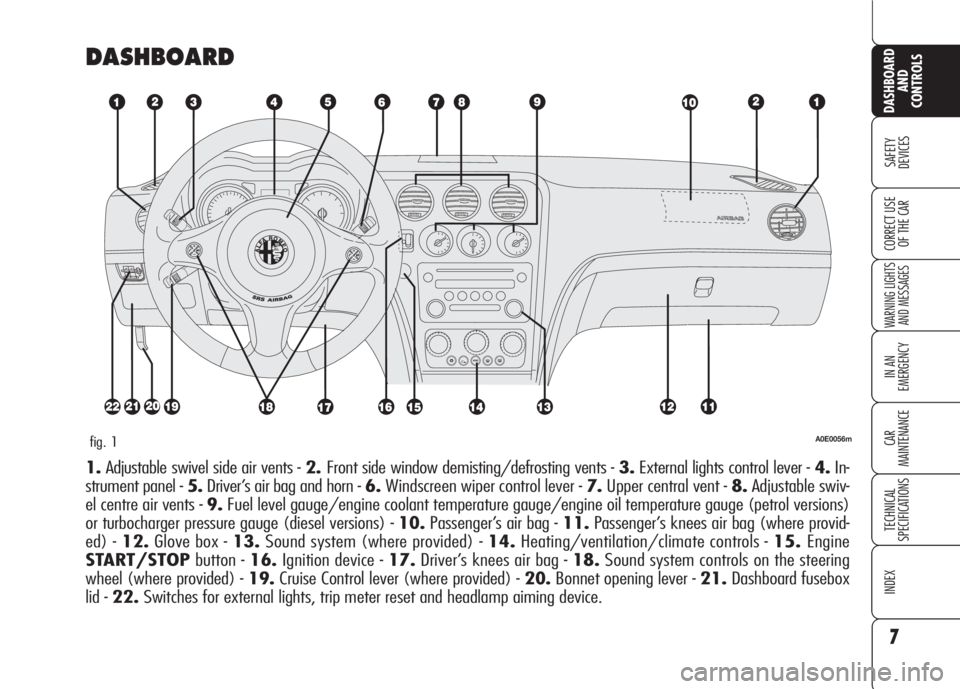
DASHBOARD
A0E0056mfig. 1
1.Adjustable swivel side air vents - 2.Front side window demisting/defrosting vents - 3.External lights control lever - 4.In-
strument panel - 5.Driver’s air bag and horn -6.Windscreen wiper control lever - 7.Upper central vent - 8.Adjustable swiv-
el centre air vents - 9.Fuel level gauge/engine coolant temperature gauge/engine oil temperature gauge (petrol versions)
or turbocharger pressure gauge (diesel versions) - 10.Passenger’s air bag - 11.Passenger’s knees air bag (where provid-
ed) - 12.Glove box - 13.Sound system (where provided) - 14.Heating/ventilation/climate controls - 15.Engine
START/STOPbutton - 16.Ignition device - 17.Driver’s knees air bag - 18.Sound system controls on the steering
wheel (where provided) - 19.Cruise Control lever (where provided) - 20.Bonnet opening lever - 21.Dashboard fusebox
lid - 22.Switches for external lights, trip meter reset and headlamp aiming device.
Page 12 of 303
10
SAFETY
DEVICES
WARNING
LIGHTS AND
MESSAGES
IN AN
EMERGENCY
CAR
MAINTENANCE
TECHNICAL
SPECIFICATIONS
INDEX
CORRECT USE
OF THE CAR
DASHBOARD
AND
CONTROLS
ALFA ROMEO
CODE SYSTEM
To further protect you car from theft, it
has been fitted with an engine immo-
bilising system. This system is auto-
matically activated when the electronic
key is removed.
An electronic device, in fact, is fitted in
each electronic key grip. The device
transmits a radio-frequency signal when
the engine is started through a special
aerial built into the ignition switch on the
dashboard. The modulated signal, which
changes each time the engine is start-
ed, is the “password”, by means of
which the control unit recognises the
electronic key and enables to start the
engine.
SYMBOLS
Special coloured labels have been at-
tached near or actually on some of the
components of your car. These labels
bear symbols that remind you of the pre-
cautions to be taken as regards that par-
ticular component.
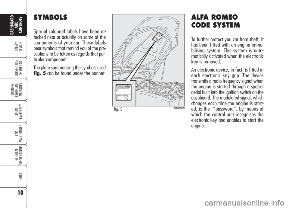
The plate summarising the symbols used
fig. 5can be found under the bonnet.
A0E0138mfig. 5
Page 19 of 303
17
SAFETY
DEVICES
WARNING LIGHTS
AND MESSAGES
IN AN
EMERGENCY
CAR
MAINTENANCE
TECHNICAL
SPECIFICATIONS
INDEX
DASHBOARD
AND
CONTROLS
CORRECT USE
OF THE CAR
Depending on the markets, the trigger-
ing of the alarm will activate the siren
and the hazard warning lights (for about
26 seconds). The methods of operation
and the number of cycles may vary de-
pending on the versions/markets.
A maximum number of sound/sight cy-
cles is however envisaged. Once the
alarm cycle is over, the system will re-
store its normal operation.
IMPORTANTCentral door unlocking
by the emergency electronic key will not
deactivate the alarm, therefore with
alarm on the siren will activate when
opening one of the doors or the boot.
To deactivate the siren see paragraph
“How to deactivate the alarm”.
IMPORTANTThe engine immobiliser
function is guaranteed by the Alfa
Romeo CODE system, which is auto-
matically activated when the electronic
key is removed from the ignition device.
HOW TO ACTIVATE
THE ALARM
With the doors, bonnet and boot shut
and electronic key removed from igni-
tion switch, point the electronic key in
the direction of the car, then press and
release the button
Á.
With the exception of certain markets,
the system sounds a “beep” and the
doors are locked.
Engagement of the alarm is preceded
by a self-diagnostic test characterised by
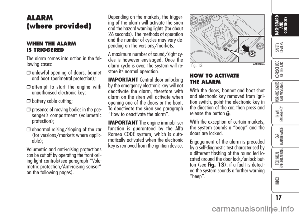
a different flashing of the round led lo-
cated around the door lock/unlock but-
ton (see fig. 13): if a fault is detect-
ed the system sounds a further warning
“beep”.
ALARM
(where provided)
WHEN THE ALARM
IS TRIGGERED
The alarm comes into action in the fol-
lowing cases:
❒unlawful opening of doors, bonnet
and boot (perimetral protection);
❒attempt to start the engine with
unauthorised electronic key;
❒ battery cable cutting;
❒ presence of moving bodies in the pas-
senger’s compartment (volumetric
protection);
❒abnormal raising/sloping of the car
(for versions/markets where applic-
able);
Volumetric and anti-raising protections
can be cut off by operating the front ceil-
ing light controls(see paragraph “Volu-
metric protection/Anti-raising sensor”
on the following pages).
A0E0025mfig. 13
Page 20 of 303
HOW TO DEACTIVATE
THE ALARM
Press button Ë. The system will react as
follows (with the exception of certain
markets):
❒two brief flashes of the direction in-
dicators;
❒two brief “beeps”;
❒door unlocking.
The alarm can be deactivated by fitting
the electronic key into the ignition
switch.
IMPORTANTOn certain versions any
attempt to break in detected by the sys-
tem will be indicated by a warning mes-
sage on the instrument panel display
when fitting the electronic key into the
ignition switch.VOLUMETRIC PROTECTION/
ANTI-RAISING SENSORS
To make sure that the protection sensors
are working properly, check that win-
dows and sunroof (where provided) are
shut.
This function can be cut out (for exam-
ple if you leave animals on the car) by
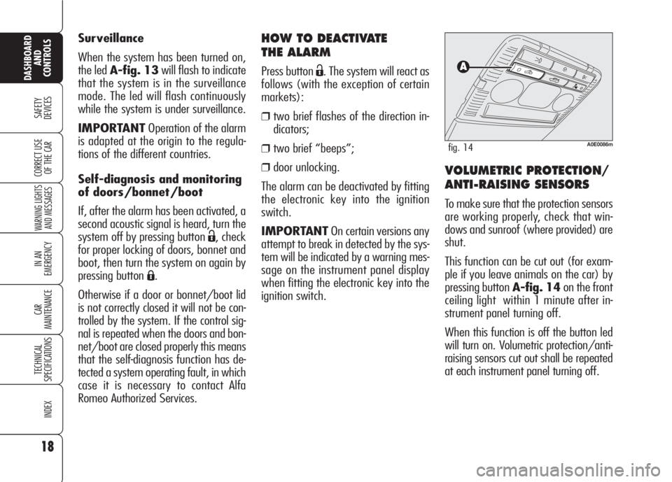
pressing button A-fig. 14on the front
ceiling light within 1 minute after in-
strument panel turning off.
When this function is off the button led
will turn on. Volumetric protection/anti-
raising sensors cut out shall be repeated
at each instrument panel turning off. Surveillance
When the system has been turned on,
the led A-fig. 13will flash to indicate
that the system is in the surveillance
mode. The led will flash continuously
while the system is under surveillance.
IMPORTANTOperation of the alarm
is adapted at the origin to the regula-
tions of the different countries.
Self-diagnosis and monitoring
of doors/bonnet/boot
If, after the alarm has been activated, a
second acoustic signal is heard, turn the
system off by pressing button
Ë, check
for proper locking of doors, bonnet and
boot, then turn the system on again by
pressing button
Á.
Otherwise if a door or bonnet/boot lid
is not correctly closed it will not be con-
trolled by the system. If the control sig-
nal is repeated when the doors and bon-
net/boot are closed properly this means
that the self-diagnosis function has de-
tected a system operating fault, in which
case it is necessary to contact Alfa
Romeo Authorized Services.
18
SAFETY
DEVICES
WARNING LIGHTS
AND MESSAGES
IN AN
EMERGENCY
CAR
MAINTENANCE
TECHNICAL
SPECIFICATIONS
INDEX
DASHBOARD
AND
CONTROLS
CORRECT USE
OF THE CAR
A0E0086mfig. 14
Page 84 of 303
82
SAFETY
DEVICES
WARNING
LIGHTS AND
MESSAGES
IN AN
EMERGENCY
CAR
MAINTENANCE
TECHNICAL
SPECIFICATIONS
INDEX
CORRECT USE
OF THE CAR
DASHBOARD
AND
CONTROLS
Resetting the power supply
cut-off switch
(where provided)The switch is located inside the fuse box
at battery positive terminal.
To reset the power supply cut-off switch,
proceed as follows:
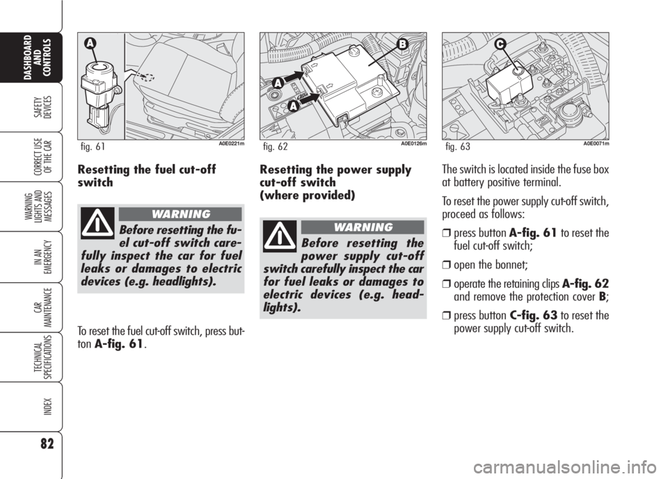
❒press button A-fig. 61to reset the
fuel cut-off switch;
❒open the bonnet;
❒operate the retaining clips A-fig. 62
and remove the protection cover B;
❒press buttonC-fig. 63to reset the
power supply cut-off switch.
A0E0126mfig. 62
Before resetting the
power supply cut-off
switch carefully inspect the car
for fuel leaks or damages to
electric devices (e.g. head-
lights).
WARNING
A0E0071mfig. 63
Resetting the fuel cut-off
switch
Before resetting the fu-
el cut-off switch care-
fully inspect the car for fuel
leaks or damages to electric
devices (e.g. headlights).
WARNING
To reset the fuel cut-off switch, press but-
tonA-fig. 61.
A0E0221mfig. 61
Page 107 of 303

105
SAFETY
DEVICES
WARNING
LIGHTS AND
MESSAGES
IN AN
EMERGENCY
CAR
MAINTENANCE
TECHNICAL
SPECIFICATIONS
INDEX
CORRECT USE
OF THE CAR
DASHBOARD
AND
CONTROLS
Improper bonnet closing is indicated (on
certain versions) by the instrument pan-
el warning light
´(where provided), or
by symbol
Sand a message on the
display (see section “Warning lights and
messages”).
IMPORTANTAlways check that the
bonnet is closed properly to avoid its
opening while the car is travelling.
BONNET
TO OPEN THE BONNET
Proceed as follows:
❒pull lever A-fig. 98until hearing
the releasing click;
❒pull leverB-fig. 99and raise the
bonnet keeping the lever pulled
IMPORTANTBonnet raising is aided
by two gas springs. Do not tamper with
these springs and guide the bonnet
while raising it.
IMPORTANT Before opening the bon-
net, check that windscreen wiper arms
are not lifted from the windscreen.A0E0122mfig. 98
A0E0158mfig. 99
TO CLOSE THE BONNET
Lower the bonnet at approx. 20 cen-
timetres from the engine compartment
and then let it drop, ensuring that it is
fully closed and not just held in position
by the safety catch. If the bonnet does
not close properly, do not push it down
but open it again and repeat the above
procedure.
Carry out operations
only when the car is
stationary.
WARNING
For safety reasons the
bonnet must be closed
properly to avoid its opening
while the car is travelling.
Therefore, always check it is
properly closed and the catch
engaged. Should you notice
that the catch is not perfectly
engaged when travelling, stop
the car immediately and close
the bonnet.
WARNING
Page 167 of 303
165
SAFETY
DEVICES
IN AN
EMERGENCY
CAR
MAINTENANCE
TECHNICAL
SPECIFICATIONS
INDEX
CORRECT USE
OF THE CAR
DASHBOARD
AND
CONTROLS
WARNING
LIGHTS AND
MESSAGES
W W
A A
R R
N N
I I
N N
G G
L L
I I
G G
H H
T T
S S
A A
N N
D D
M M
E E
S S
S S
A A
G G
E E
S S
LOW BRAKE FLUID/HANDBRAKE ON ..................... 167
BRAKE PAD WEAR ............................................. 167
SEAT BELTS NOT FASTENED ................................. 167
AIR BAG FAILURE................................................ 168
PASSANGER’S FRONT AIR BAGS DEACTIVATED ........ 169
ENGINE COOLANT HIGH TEMPERATURE.................. 169
ENGINE OIL HIGH TEMPERATURE .......................... 170
LOW ENGINE OIL PRESSURE/
EXHAUST OIL..................................................... 170
LOW BATTERY CHARGE ....................................... 170
INCOMPLETE DOOR LOCKING ............................... 171
BONNET OPEN ................................................... 171
BOOT OPEN....................................................... 171
INJECTION SYSTEM FAILURE/
EOBD SYSTEM FAILURE....................................... 171
CAR PROTECTION SYSTEM FAILURE/
STEERING LOCK INHIBITION................................. 172
ALARM FAILURE/BREAK-IN ATTEMPT
ELECTRONIC KEY NOT RECOGNIZED ...................... 172
POSSIBLE PRESENCE OF ICE ON THE ROAD............ 173
PRE-HEATING GLOW PLUGS/
PRE-HEATING GLOW PLUG FAILURE ....................... 173
WATER IN DIESEL FUEL FILTER ............................. 174
INERTIAL FUEL CUT-OFF SWITCHED ON ................. 174
ABS SYSTEM FAILURE......................................... 175
EBD SYSTEM FAILURE......................................... 175VDC SYSTEM .................................................... 175
HILL HOLDER FAILURE ........................................ 176
ASR SYSTEM (WHEEL ANTISKID SYSTEM) ............. 176
EXTERNAL LIGHTS FAILURE .................................. 176
BRAKE LIGHTS FAILURE ....................................... 177
REAR FOGLIGHTS ............................................... 177
FRONT FOG LIGHTS ............................................ 177
SIDE/TAILLIGHTS/FOLLOW ME HOME .................. 177
DIPPED BEAM HEADLIGHTS.................................. 177
MAIN BEAM HEADLIGHTS .................................... 177
LEFT-HAND DIRECTION INDICATOR ........................ 177
RIGHT-HAND DIRECTION INDICATOR ...................... 177
LIGHT SENSOR FAILURE........................................ 178
RAIN SENSOR FAILURE......................................... 178
PARKING SENSORS FAILURE ................................ 178
FUEL RESERVE – LIMITED CRUISING RANGE .......... 178
CRUISE CONTROL .............................................. 178
DIESEL PARTICULATE FILTER CLOGGED .................. 178
ANTIPINCH SYSTEM FAILURE ............................... 179
WINDSCREEN WASHER FLUID LOW LEVEL ............. 179
SPEED LIMIT EXCEEDED ..................................... 179
T.P.M.S. SYSTEM FAILURE ................................... 179
CHECK TYRE PRESSURE ...................................... 179
LOW INFLATION PRESSURE ................................. 180
TYRE PRESSURE UNSUITABLE FOR SPEED ............. 180
Page 173 of 303

171
SAFETY
DEVICES
IN AN
EMERGENCY
CAR
MAINTENANCE
TECHNICAL
SPECIFICATIONS
INDEX
CORRECT USE
OF THE CAR
DASHBOARD
AND
CONTROLS
WARNING
LIGHTS AND
MESSAGES
BOOT OPEN
On certain versions message
and symbol
R(red) are
displayed to indicate that boot is
open.
BONNET OPEN
(where provided)
On certain versions message
and symbol
S(red) are displayed to
indicate that bonnet is open.
INJECTION SYSTEM
FAILURE (diesel
versions - amber)
EOBD SYSTEM
FAILURE
(petrol versions -
amber)
(optional for
versions/markets
where applicable)
Injection system failure
Fitting the key into the ignition device
the warning light turns on, but it should
go off when the engine has started.
The warning light stays on or it turns on
when travelling to indicate a malfunc-
tion in the injection/exhaust system
with possible lack of performance, poor
driveability and high consumption.
In these conditions it is possible to con-
tinue driving without however requiring
heavy effort or high speed from the en-
gine. In any case, contact Alfa Romeo
Authorized Services as soon as possible.EOBD system failure
(optional for versions/
markets where applicable)
Under normal conditions, fitting the elec-
tronic key into the ignition device, the
warning light turns on, but it should go
off when the engine has started. This in-
dicates proper operation of the warn-
ing light.
If the warning light stays on or turns on
when travelling:
– glowing steadily (on certain ver-
sions together with the message on the
display): means a fault in the sup-
ply/ignition system which could cause
high emissions at the exhaust, possible
lack of performance, poor handling and
high consumption levels. In these con-
ditions it is possible to continue driving
without however requiring heavy effort
or high speed from the engine. Pro-
longed use of the car with the warning
light on may cause damages. Contact
Alfa Romeo Authorized Services as soon
as possible.
The warning light goes off if the fault
disappears, but it is however stored by
the system.
INCOMPLETE DOOR
LOCKING (red)
The warning light (where pro-
vided) (or symbol on the display) turns
on when one or more doors, the boot or
the bonnet (where provided) are not
properly shut.
U´
S
R
Page 227 of 303
225
SAFETY
DEVICES
WARNING
LIGHTS AND
MESSAGES
IN AN
EMERGENCY
TECHNICAL
SPECIFICATIONS
INDEX
CORRECT USE
OF THE CAR
DASHBOARD
AND
CONTROLS
CAR
MAINTENANCE
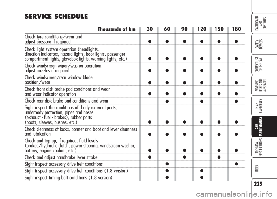
30 60 90 120 150 180
●●●●●●
●●●●●●
●●●●●●
●●●●●●
●●●●●●
●●●
●●●●●●
●●●●●●
●●●●●●
●●●
●●
●●
●●
SERVICE SCHEDULE
Thousands of km
Check tyre conditions/wear and
adjust pressure if required
Check light system operation (headlights,
direction indicators, hazard lights, boot lights, passenger
compartment lights, glovebox lights, warning lights, etc.)
Check windscreen wiper/washer operation,
adjust nozzles if required
Check windscreen/rear window blade
position/wear
Check front disk brake pad conditions and wear
and wear indicator operation
Check rear disk brake pad conditions and wear
Sight inspect the conditions of: body external parts,
underbody protection, pipes and hoses
(exhaust - fuel - brakes), rubber parts
(boots, sleeves, bushes, etc.)
Check cleanness of locks, bonnet and boot and lever cleanness
and lubrication
Check and top up, if required, fluid levels
(brakes/hydraulic clutch, power steering, windscreen washer,
battery, engine coolant, etc.)
Check and adjust handbrake lever stroke
Sight inspect accessory drive belt conditions
Sight inspect accessory drive belt conditions (1.8 version)
Sight inspect timing belt conditions (1.8 version)