change Alfa Romeo 159 2008 Owner handbook (in English)
[x] Cancel search | Manufacturer: ALFA ROMEO, Model Year: 2008, Model line: 159, Model: Alfa Romeo 159 2008Pages: 303, PDF Size: 5.18 MB
Page 7 of 303
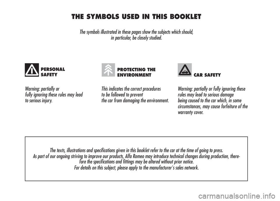
THE SYMBOLS USED IN THIS BOOKLET
The symbols illustrated in these pages show the subjects which should,
in particular, be closely studied.
Warning: partially or
fully ignoring these rules may lead
to serious injury.This indicates the correct procedures
to be followed to prevent
the car from damaging the environment.Warning: partially or fully ignoring these
rules may lead to serious damage
being caused to the car which, in some
circumstances, may cause forfeiture of the
warranty cover.
The texts, illustrations and specifications given in this booklet refer to the car at the time of going to press.
As part of our ongoing striving to improve our products, Alfa Romeo may introduce technical changes during production, there-
fore the specifications and fittings may be altered without prior notice.
For details on this subject, please apply to the manufacturer's sales network.
PERSONAL
SAFETYPROTECTING THE
ENVIRONMENT CAR SAFETY
Page 12 of 303
10
SAFETY
DEVICES
WARNING
LIGHTS AND
MESSAGES
IN AN
EMERGENCY
CAR
MAINTENANCE
TECHNICAL
SPECIFICATIONS
INDEX
CORRECT USE
OF THE CAR
DASHBOARD
AND
CONTROLS
ALFA ROMEO
CODE SYSTEM
To further protect you car from theft, it
has been fitted with an engine immo-
bilising system. This system is auto-
matically activated when the electronic
key is removed.
An electronic device, in fact, is fitted in
each electronic key grip. The device
transmits a radio-frequency signal when
the engine is started through a special
aerial built into the ignition switch on the
dashboard. The modulated signal, which
changes each time the engine is start-
ed, is the “password”, by means of
which the control unit recognises the
electronic key and enables to start the
engine.
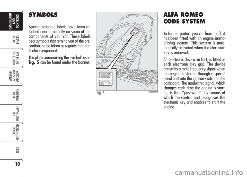
SYMBOLS
Special coloured labels have been at-
tached near or actually on some of the
components of your car. These labels
bear symbols that remind you of the pre-
cautions to be taken as regards that par-
ticular component.
The plate summarising the symbols used
fig. 5can be found under the bonnet.
A0E0138mfig. 5
Page 14 of 303
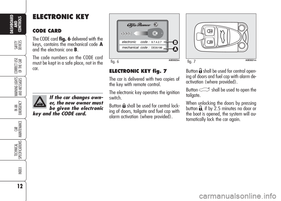
ButtonËshall be used for central open-
ing of doors and fuel cap with alarm de-
activation (where provided).
Button
`shall be used to open the
tailgate.
When unlocking the doors by pressing
button
Ë, if by 2.5 minutes no door or
the boot is opened, the system will au-
tomatically lock the car again.
ELECTRONIC KEY fig. 7
The car is delivered with two copies of
the key with remote control.
The electronic key operates the ignition
switch.
Button
Áshall be used for central lock-
ing of doors, tailgate and fuel cap with
alarm activation (where provided).
ELECTRONIC KEY
CODE CARD
The CODE card fig. 6delivered with the
keys, contains the mechanical codeA
and the electronic one B.
The code numbers on the CODE card
must be kept in a safe place, not in the
car.
12
SAFETY
DEVICES
WARNING LIGHTS
AND MESSAGES
IN AN
EMERGENCY
CAR
MAINTENANCE
TECHNICAL
SPECIFICATIONS
INDEX
DASHBOARD
AND
CONTROLS
CORRECT USE
OF THE CAR
A0E0023mfig. 6
If the car changes own-
er, the new owner must
be given the electronic
key and the CODE card.
A0E0021mfig. 7
Page 16 of 303
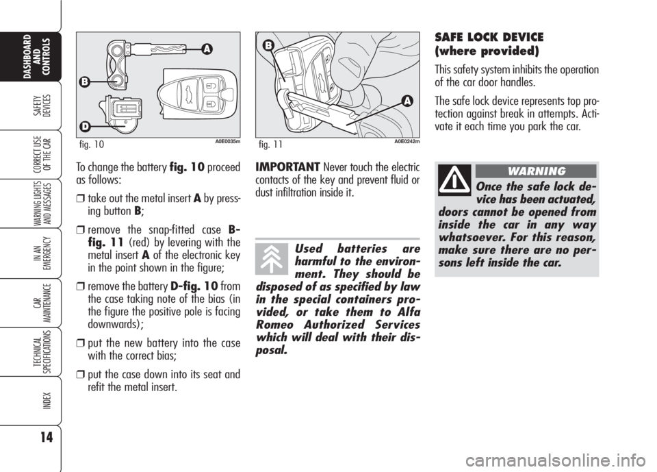
To change the battery fig. 10proceed
as follows:
❒take out the metal insert Aby press-
ing button B;
❒remove the snap-fitted case B-
fig. 11(red) by levering with the
metal insert Aof the electronic key
in the point shown in the figure;
❒remove the battery D-fig. 10from
the case taking note of the bias (in
the figure the positive pole is facing
downwards);
❒put the new battery into the case
with the correct bias;
❒put the case down into its seat and
refit the metal insert.
14
SAFETY
DEVICES
WARNING LIGHTS
AND MESSAGES
IN AN
EMERGENCY
CAR
MAINTENANCE
TECHNICAL
SPECIFICATIONS
INDEX
CORRECT USE
OF THE CAR
DASHBOARD
AND
CONTROLS
A0E0035mfig. 10A0E0242mfig. 11
Used batteries are
harmful to the environ-
ment. They should be
disposed of as specified by law
in the special containers pro-
vided, or take them to Alfa
Romeo Authorized Services
which will deal with their dis-
posal.
IMPORTANTNever touch the electric
contacts of the key and prevent fluid or
dust infiltration inside it.
SAFE LOCK DEVICE
(where provided)
This safety system inhibits the operation
of the car door handles.
The safe lock device represents top pro-
tection against break in attempts. Acti-
vate it each time you park the car.
Once the safe lock de-
vice has been actuated,
doors cannot be opened from
inside the car in any way
whatsoever. For this reason,
make sure there are no per-
sons left inside the car.
WARNING
Page 34 of 303
32
SAFETY
DEVICES
WARNING LIGHTS
AND MESSAGES
IN AN
EMERGENCY
CAR
MAINTENANCE
TECHNICAL
SPECIFICATIONS
INDEX
DASHBOARD
AND
CONTROLS
CORRECT USE
OF THE CAR
Selecting “Date” and “Clock”:
❒briefly press button MENUto select
the first value to change (e.g. hours/
minutes or year/month/day);
❒operate buttons +or–(by single
press) to select the new setting;
❒briefly press button MENUto store
the new setting and to go to the next
setup menu option, if this is the last
one you will go back to the previously
selected option of the main menu.
ENGINE OIL LEVEL
INDICATION
Fitting the electronic key into the igni-
tion device, the display will show for a
few seconds the engine oil level. At this
stage, to clear this indication and to go
to next screen, press button MENU.
Low oil level will be indicated by a ded-
icated warning message on the display.
IMPORTANT Check the proper en-
gine oil level on the dipstick (see para-
graph “Checking levels” in section “Car
maintenance”).
IMPORTANTProper engine oil level
shall be checked with the car on level
ground.
IMPORTANT To read the correct oil
level after fitting the electronic key, wait
for about 2 seconds before starting the
engine.
IMPORTANT Engine oil level could in-
crease after a long stop. Selecting an option of the main
menu with submenu:❒briefly press button MENUto display
the first submenu option;
❒operate buttons +or–(by single
press) to scroll all submenu options;
❒briefly press button MENUto select
the displayed submenu option and to
enter the corresponding setup menu;
❒operate buttons +or–(by single
press) to select the new setting of this
submenu option;
❒briefly press button MENUto store
the new setting and go back to the
previously selected submenu option.
Page 38 of 303
36
SAFETY
DEVICES
WARNING LIGHTS
AND MESSAGES
IN AN
EMERGENCY
CAR
MAINTENANCE
TECHNICAL
SPECIFICATIONS
INDEX
DASHBOARD
AND
CONTROLS
CORRECT USE
OF THE CAR
Setting the date (Date)
This function enables to update the date
(year - month - day).
Proceed as follows:
❒briefly press button MENU: “year”
will flash on the display;
❒press button +or–to select the re-
quired volume;
❒briefly press button MENU: “month”
will flash on the display;
❒press button +or–to select the re-
quired volume;
❒briefly press button MENU: “day”
will flash on the display;
❒press button +or–to adjust;
IMPORTANTEvery press (pulse) on
the button +/–increases/decreases by
one unit. Keeping button +/–pressed
obtains fast increase/decrease. When
you are near the required setting com-
plete adjustment with single presses.
❒briefly press button MENUto go
back to the menu screen or press the
button for long to go back to the stan-
dard screen.Audio Info Repetition
(Audio Rpt.) (where provided)
This function enables to display sound
system information.
❒Radio: selected radio station fre-
quency or RDS message, automatic
tuning activation or AutoSTore;
❒Audio CD, MP3 CD: selected track
number;
❒CD Changer: CD number and track
number;To activate/deactivate (ON/OFF) in-
fo displaying proceed as follows:
❒briefly press button MENU: the dis-
play will show ONorOFF(accord-
ing to previous setting);
❒press button +or–to select the re-
quired source;
❒briefly press button MENUto go
back to the menu screen or press the
button for long to go back to the stan-
dard screen.
According to the audio source selected,
below the time will be displayed the
symbol of the current source.
Page 60 of 303

58
SAFETY
DEVICES
WARNING
LIGHTS AND
MESSAGES
IN AN
EMERGENCY
CAR
MAINTENANCE
TECHNICAL
SPECIFICATIONS
INDEX
CORRECT USE
OF THE CAR
DASHBOARD
AND
CONTROLS
To guarantee perfect
and regular sensor op-
eration do not apply
stickers in the “monitoring”
area between sensor and wind-
screen. Keep windscreen and
sensor clean and avoid to accu-
mulate dust or other sub-
stances.
AUTOMATIC TWO-/
THREE-ZONE
CLIMATE CONTROL
SYSTEM
(where provided)
DESCRIPTION
The car is fitted with a two-/three-zone
climate control system which makes it
possible to separately adjust the air tem-
perature in the two/three passenger’s
compartment areas to reach the required
comfort.
For top quality temperature control in
the two/three areas of the passenger's
compartment, the system is fitted with
external temperature sensor, passen-
ger's compartment temperature sensor
and two-side sun radiation sensor.
The climate control system automatically
controls and adjusts the following pa-
rameters and functions:
❒air temperature at driver/passengers
vents;
❒fan speed;
❒air distribution at driver/passenger
vents;
❒compressor activation;
❒air recirculation.
The following parameters and functions
can be set or changed manually:
❒required temperature;
❒fan speed;
❒air distribution on seven levels ;
❒compressor on/off;
❒window demisting/defrosting;
❒air recirculation;
❒one-zone function.
The system is fitted with AQS (Air Qual-
ity System) sensor (where provided),
that turns on air recirculation automati-
cally when it detects the presence of out-
side polluted air (for example in queues
and tunnels).
Where provided, the system is integrat-
ed with an anti-misting sensor A-fig. 48
set behind the driving mirror, capable of
“monitoring” a preset internal area of the
windscreen and of intervening automat-
ically to prevent or to reduce window mist-
A0E0091mfig. 48
ing up, also with climate control OFF,
through a proper strategy. This sensor can
be deactivated through any manual sys-
tem control when the strategy is operat-
ing. The sensor is enabled at each start-
up and in any case when the user press-
es one of the AUTO buttons.
Page 65 of 303

63
SAFETY
DEVICES
WARNING
LIGHTS AND
MESSAGES
IN AN
EMERGENCY
CAR
MAINTENANCE
TECHNICAL
SPECIFICATIONS
INDEX
CORRECT USE
OF THE CAR
DASHBOARD
AND
CONTROLS
FAN SPEED ADJUSTMENT
Press buttons +/–to increase or to de-
crease the fan speed.
The fan speed is shown by the lit bars on
the display:
❒min fan speed = one bar lit;
❒max fan speed = 6 bars lit;
At starting, if climate control system is
operating in automatic mode, the fan
speed is kept at minimum until the en-
gine has started.
With compressor on and engine running,
the fan speed cannot fall below the min.
speed.
The fan can be cut off (all bars off) on-
ly if the climate control compressor has
been switched off by pressing button
√.
To restore automatic fan speed control
after a manual adjustment, press but-
tons AUTO. AUTO will also go off if the system (spe-
cially when compressor is turned off
manually) cannot reach or cannot keep
the required temperature.
Button
√will not turn off AUTO if the
system can keep the required comfort.
It is inadvisable to use
air recirculation on
rainy/cold days as it would
considerably increase the pos-
sibility of windows misting up
inside.
WARNING
AUTOMATIC OPERATION
(AUTO BUTTON)
Pressing button AUTO (front and rear
controls) the displays will show FULL AU-
TO and the system will automatically ad-
just:
❒fan speed;
❒air distribution in passenger com-
partment;
❒air recirculation;
❒compressor;
and it will cancel all the previous man-
ual adjustments.
Wording FULL will disappear from the
display of the involved area (driver or
front passenger side or rear passenger
side) when performing whatever oper-
ation (excluding temperature change).
Page 70 of 303
68
SAFETY
DEVICES
WARNING
LIGHTS AND
MESSAGES
IN AN
EMERGENCY
CAR
MAINTENANCE
TECHNICAL
SPECIFICATIONS
INDEX
CORRECT USE
OF THE CAR
DASHBOARD
AND
CONTROLS
POLLEN FILTER/ ACTIVATED
CARBON POLLEN FILTER
According to versions, the car can be fit-
ted with pollen filter or activated carbon
pollen filter (where provided). The filter
has the specific capability of admitting to
the passenger compartment purified air,
free from particles such as dust, pollen,
etc. The filtering action takes place un-
der all air inlet conditions and it is clear-
ly most effective with the windows shut.
Have the conditions of the filter checked
by Alfa Romeo Authorized Services at
least once a year, preferably at the on-
set of summer. If the car is used main-
ly in polluted or dusty areas it should be
checked and if necessary replaced at
shorter intervals than specified in the
Service Schedule (see section “Car
Maintenance”). AQS function (Air Quality
System) (where provided)
The AQS function turns on automatical-
ly air recirculation when it detects the
presence of polluted air (e.g. in queues
and tunnels).
IMPORTANTWith AQS function on,
after a preset time with recirculation on,
the compressor will enable outside air
inlet (for about 1 minute) to change air
inside the passenger compartment, re-
gardless of outside air pollution level.
IMPORTANTThe AQS function is dis-
abled when the outside temperature is
cold to prevent window misting up. To
reactivate this function, press button
v. Led “A” on button vwill
turn on to indicate that the function is
on.
Failure to replace the fil-
ter may considerably re-
duce the effectiveness of
the climate control system up to
blocking the air flow from the
outlets and vents.
In certain weather con-
ditions (e.g. outside
temperature around
0°C) and with automatic air re-
circulation control on, mist may
form on the windows. In this
case press button vto
switch off recirculation and if
necessary press button + to in-
crease the flow of air to the
windscreen.
With the outside tem-
perature below -1°C the
climate control compres-
sor is unable to work. It is
therefore inadvisable to use the
inside air recirculation function
with low outside temperature
as windows may mist over
quickly.
Page 72 of 303
70
SAFETY
DEVICES
WARNING
LIGHTS AND
MESSAGES
IN AN
EMERGENCY
CAR
MAINTENANCE
TECHNICAL
SPECIFICATIONS
INDEX
CORRECT USE
OF THE CAR
DASHBOARD
AND
CONTROLS
EXTERNAL LIGHTS
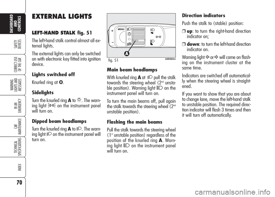
LEFT-HAND STALK fig. 51
The left-hand stalk control almost all ex-
ternal lights.
The external lights can only be switched
on with electronic key fitted into ignition
device.
Lights switched off
Knurled ring at O.
Sidelights
Turn the knurled ring Ato
6. The warn-
ing light
3on the instrument panel
will turn on.
Dipped beam headlamps
Turn the knurled ring Ato
2. The warn-
ing light
2on the instrument panel will
turn on.Main beam headlamps
With knurled ring Aat
2pull the stalk
towards the steering wheel (2ndunsta-
ble position). Warning light
1on the
instrument panel will turn on.
To turn the main beams off, pull again
the stalk towards the steering wheel (2
nd
unstable position).
Flashing the main beams
Pull the stalk towards the steering wheel
(1
stunstable position) regardless of the
position of the knurled ring A. Warn-
ing light
1on the instrument panel
will turn on. Direction indicators
Push the stalk to (stable) position:
❒up: to turn the right-hand direction
indicator on;
❒down: to turn the left-hand direction
indicator on.
Warning light
Îor¥will come on flash-
ing on the instrument cluster at the
same time.
Indicators are switched off automatical-
ly when the steering wheel is straight-
ened.
If you want to show that you are about
to change lane, move the left-hand stalk
to unstable position. The required direc-
tion indicator will flash 3 times and then
it will turn off automatically.A0E0064mfig. 51