Alfa Romeo 166 2006 Owner handbook (in English)
Manufacturer: ALFA ROMEO, Model Year: 2006, Model line: 166, Model: Alfa Romeo 166 2006Pages: 272, PDF Size: 4.17 MB
Page 101 of 272
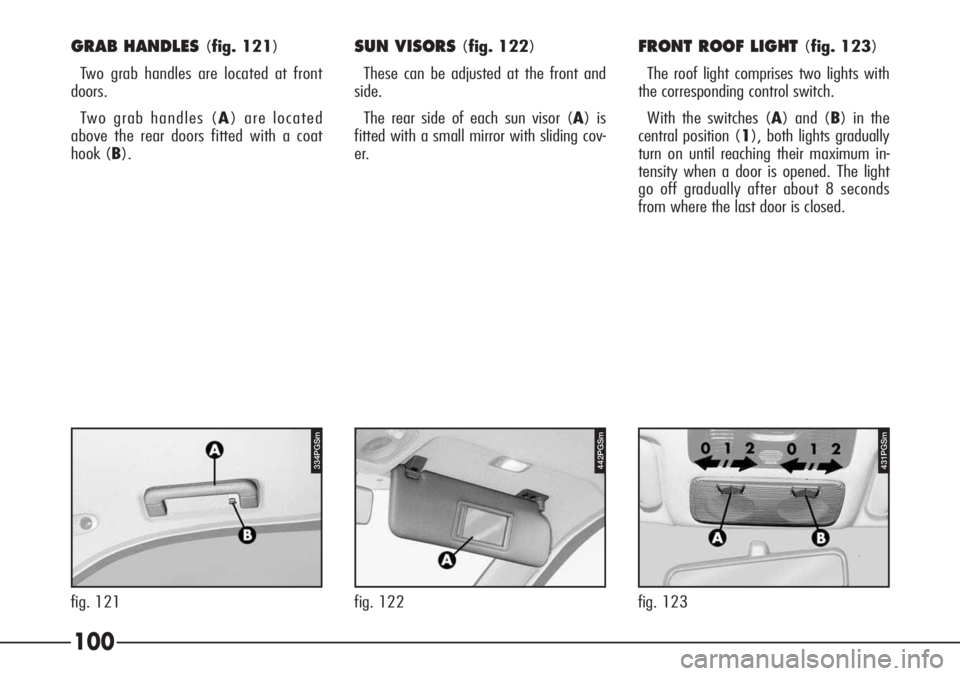
GRAB HANDLES (fig. 121)
Two grab handles are located at front
doors.
Two grab handles (A) are located
above the rear doors fitted with a coat
hook (B).
442PGSm
fig. 122
431PGSm
fig. 123
100
334PGSm
fig. 121
SUN VISORS (fig. 122)
These can be adjusted at the front and
side.
The rear side of each sun visor (A) is
fitted with a small mirror with sliding cov-
er.FRONT ROOF LIGHT (fig. 123)
The roof light comprises two lights with
the corresponding control switch.
With the switches (A) and (B) in the
central position (1), both lights gradually
turn on until reaching their maximum in-
tensity when a door is opened. The light
go off gradually after about 8 seconds
from where the last door is closed.
Page 102 of 272
101
If a door is left open, the lights gradual-
ly go out after about 3 minutes. To turn
them on again, open another door or shut
and re-open the same one. The lights go
out when the ignition key is turned to
MAR(with the doors closed) or engag-
ing central door locking.
Moving switches (A) and (B) to the
left (position 0), the lights stay off (OFF
position).
Moving switch (A) and (B) to the right
(position2), the lights stay on.
With switches (A) and (B) the lights
are turned on individually.
IMPORTANTBefore leaving the car,
make sure that both switches are in the
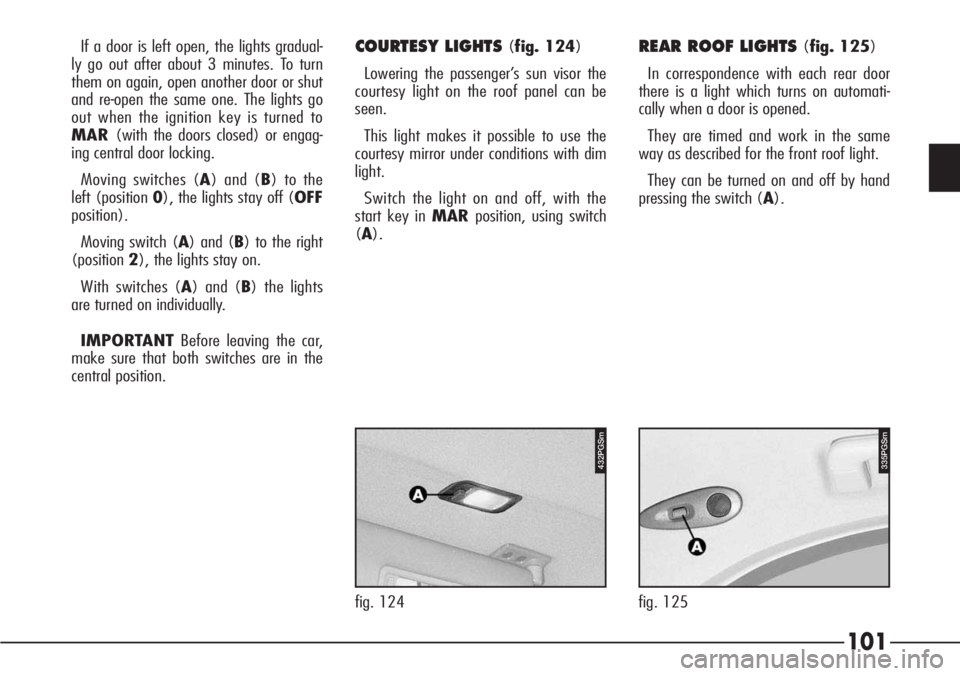
central position.COURTESY LIGHTS (fig. 124)
Lowering the passenger’s sun visor the
courtesy light on the roof panel can be
seen.
This light makes it possible to use the
courtesy mirror under conditions with dim
light.
Switch the light on and off, with the
start key in MARposition, using switch
(A).
fig. 124
432PGSm
REAR ROOF LIGHTS (fig. 125)
In correspondence with each rear door
there is a light which turns on automati-
cally when a door is opened.
They are timed and work in the same
way as described for the front roof light.
They can be turned on and off by hand
pressing the switch (A).
335PGSm
fig. 125
Page 103 of 272
102
For the installation of
the cellular phone and
connection to the provi-
sion in the car, contact only Au-
thorized Alfa Romeo Services;
this will guarantee first-rate re-
sults with no possibility of any
inconvenience that may compro-
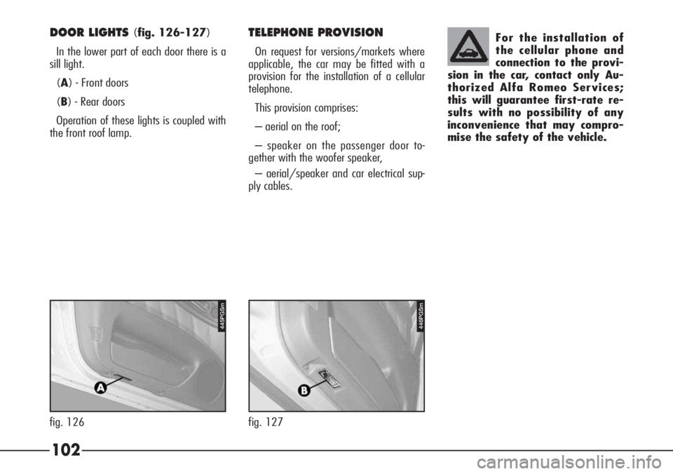
mise the safety of the vehicle.DOOR LIGHTS (fig. 126-127)
In the lower part of each door there is a
sill light.
(A) - Front doors
(B) - Rear doors
Operation of these lights is coupled with
the front roof lamp.TELEPHONE PROVISION
On request for versions/markets where
applicable, the car may be fitted with a
provision for the installation of a cellular
telephone.
This provision comprises:
– aerial on the roof;
– speaker on the passenger door to-
gether with the woofer speaker,
– aerial/speaker and car electrical sup-
ply cables.
fig. 127
446PGSm
fig. 126
P4C00057445PGSm
Page 104 of 272
103
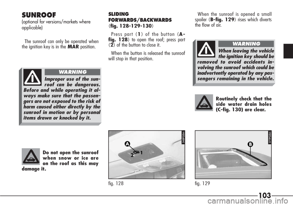
Routinely check that the
side water drain holes
(C-fig. 130) are clear.
SUNROOF
(optional for versions/markets where
applicable)
The sunroof can only be operated when
the ignition key is in theMARposition.When the sunroof is opened a small
spoiler (B-fig. 129) rises which diverts
the flow of air.
Do not open the sunroof
when snow or ice are
on the roof as this may
damage it.
SLIDING
FORWARDS/BACKWARDS
(fig. 128-129-130)
Press part (1) of the button (A-
fig. 128) to open the roof; press part
(2) of the button to close it.
When the button is released the sunroof
will stop in that position.
377PGSm
fig. 129
348PGSm
fig. 128
Improper use of the sun-
roof can be dangerous.
Before and while operating it al-
ways make sure that the passen-
gers are not exposed to the risk of
harm caused either directly by the
sunroof in motion or by personal
items drawn or knocked by it.
WARNING
When leaving the vehicle
the ignition key should be
removed to avoid accidents in-
volving the sunroof which could be
inadvertently operated by any pas-
sengers remaining in the vehicle.
WARNING
Page 105 of 272

104
REAR LIFTING
This can only be achieved when the sun-
roof is completely closed. Press the front end
(2) of the control button (A-fig. 128).
Press end (1) of the button (A-
fig. 128) to return the sunroof to the
horizontal position (roof closed).
SLIDING WING
The sunroof is equipped with manual-oper-
ated sliding wing preventing direct sun rays.
To open the wing pull handle (A-fig.
131).
When opening the sunroof, the wing is au-
tomatically pushed inside the roof panel.
When closing the sunroof, the wing comes
out partially in order to have access to the
handle for manual closing.
EMERGENCY OPERATION
(fig. 132-133-134)
If the electrical control device does not
work the sunroof can be opened manual-
ly as follows:
– Apply leverage to the points indicated
by the arrows and remove the plate with
switch (A-fig. 132).
fig. 133
349PGSm
fig. 132
A0D0119m
fig. 131
350PGSm378PGSm
fig. 130
Page 106 of 272
105
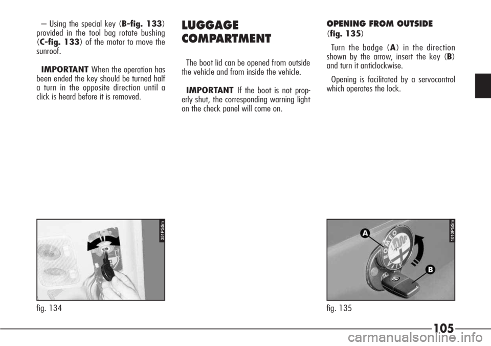
– Using the special key (B-fig. 133)
provided in the tool bag rotate bushing
(C-fig. 133) of the motor to move the
sunroof.
IMPORTANT When the operation has
been ended the key should be turned half
a turn in the opposite direction until a
click is heard before it is removed.LUGGAGE
COMPARTMENT
The boot lid can be opened from outside
the vehicle and from inside the vehicle.
IMPORTANT If the boot is not prop-
erly shut, the corresponding warning light
on the check panel will come on.
OPENING FROM OUTSIDE
(fig. 135)
Turn the badge (A) in the direction
shown by the arrow, insert the key (B)
and turn it anticlockwise.
Opening is facilitated by a servocontrol
which operates the lock.
351PGSm
fig. 134
1010PGSm
fig. 135
Page 107 of 272

1024PGSm
fig. 137
106
OPENING FROM INSIDE
(fig. 136)
To open from inside:
– With the vehicle stationary, press but-
ton (A) inside the glovebox.
Due to its position, this control cannot
be operated when the glovebox is key-
locked.
REMOTE CONTROL OPENING
(
fig. 137)
(optional for the versions/markets where
applicable)
The luggage compartment may be re-
mote opened by pressing the push-button
(A-fig. 137) on the key with metallic
insert (B), even when the electronic
alarm is ON (where installed).In this case the alarm disengages the
boot control sensor, the system (with the
exception of versions for certain markets)
sounds two beeps and the direction indi-
cators light up for about three seconds.
When the boot is closed again the con-
trol function is restored, the system (with
the exception of versions for certain mar-
kets) sounds two beeps and the direction
indicators light up for about three seconds.
574PGSm
fig. 136
Page 108 of 272
107
The gas springs are cali-
brated to guarantee
correct operation with
loading specified by the manufac-
turer. Arbitrary additions to the
boot lid (spoiler etc.) may affect
its operation and safety.
EMERGENCY OPENING
The luggage compartment lock is re-
leased by a servocontrol when opening
the bonnet from inside or using the key.
However, it is always possible to open
the luggage compartment, even in case
of insufficient battery power: just rotate
the key wider and simultaneously press
the bonnet edge by the hand.
IMPORTANTApply a moderate pres-
sure only on the bonnet edge, immediate-
ly above the lock.
LIFTING AND CLOSING
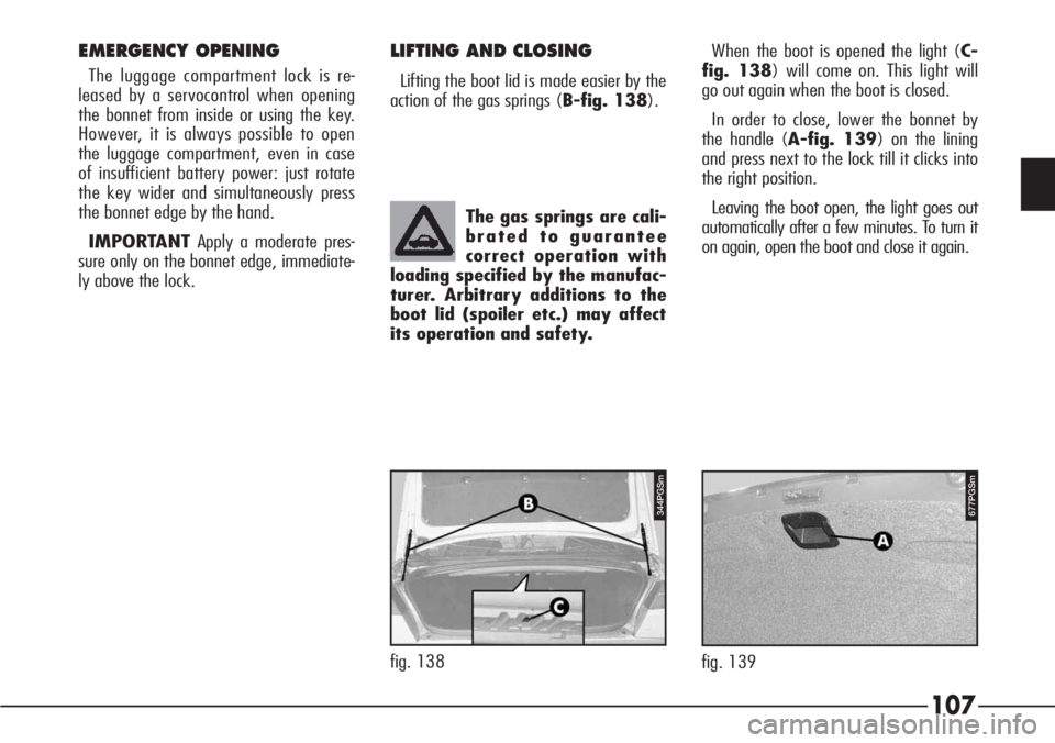
Lifting the boot lid is made easier by the
action of the gas springs (B-fig. 138).When the boot is opened the light (C-
fig. 138) will come on. This light will
go out again when the boot is closed.
In order to close, lower the bonnet by
the handle (A-fig. 139) on the lining
and press next to the lock till it clicks into
the right position.
Leaving the boot open, the light goes out
automatically after a few minutes. To turn it
on again, open the boot and close it again.
fig. 139
677PGSm344PGSm
fig. 138
Page 109 of 272
108
SECURING THE LOAD
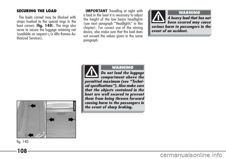
The loads carried may be blocked with
straps hooked to the special rings in the
boot corners (fig. 140). The rings also
serve to secure the luggage retaining net
(available on request c/o Alfa Romeo Au-
thorized Services).
fig. 140
678PGSm
Do not load the luggage
compartment above the
permitted maximum (see “Techni-
cal specifications”). Also make sure
that the objects contained in the
boot are well secured to prevent
them from being thrown forward
causing harm to the passengers in
the event of sharp braking.
WARNING
A heavy load that has not
been secured may cause
serious harm to passengers in the
event of an accident.
WARNINGIMPORTANT Travelling at night with
a load in the boot it is necessary to adjust
the height of the low beam headlights
(see next paragraph “Headlights” in this
chapter). For correct use of the aiming
device, also make sure that the load does
not exceed the values given in the same
paragraph.
Page 110 of 272
109
BONNET
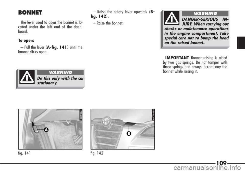
The lever used to open the bonnet is lo-
cated under the left end of the dash-
board.
To open:
– Pull the lever (A-fig. 141) until the
bonnet clicks open.
357PGSm
fig. 141
Do this only with the car
stationary.
WARNING
– Raise the safety lever upwards (B-
fig. 142).
– Raise the bonnet.
IMPORTANT Bonnet raising is aided
by two gas springs. Do not tamper with
these springs and always accompany the
bonnet while raising it.
A0D0033m
fig. 142
DANGER-SERIOUS IN-
JURY. When carrying out
checks or maintenance operations
in the engine compartment, take
special care not to bump the head
on the raised bonnet.
WARNING