Alfa Romeo 166 2006 Owner handbook (in English)
Manufacturer: ALFA ROMEO, Model Year: 2006, Model line: 166, Model: Alfa Romeo 166 2006Pages: 272, PDF Size: 4.17 MB
Page 171 of 272

170
Front sidelights
To replace the bulb (Type B – H6W,
6W):
– Remove the engine compartment cov-
er after turning the fastening pins.
– Turn counter-clockwise and remove
the direction indicator bulb holder (A-
fig. 32) without disconnecting the con-
nector to widen the working space.
– Remove the rubber cap (B) by
pulling the tab (C).– Press the two retaining tabs and re-
move the bulb holder (D- fig. 33).
– Remove the bulb (E- fig. 34) from
the bulb holder, pushing it slightly and
turning it counter-clockwise.– Fit the new bulb into the bulb holder,
pushing it slightly and turning it clock-
wise.
– Push the bulb holder down in its seat.
– Fit the rubber cap.
– Fit the direction indicator bulb holder
and lock it by turning it clockwise.
– Refit the engine compartment cover
and secure it by turning the fastening
pins.
A0D0059m
fig. 32
A0D0062m
fig. 33
A0D0063m
fig. 34
Page 172 of 272

171
Front direction indicators
To replace the bulb (Type B – PY21W,
21W, coloured):
– Remove the engine compartment cov-
er after turning the fastening pins.
– Turn counter-clockwise and remove
the bulb holder (A- fig. 35) without
disconnecting the connector.
– Remove the bulb (B- fig. 36) from
the bulb holder, pushing it slightly and
turning it counter-clockwise.– Fit the new bulb into the bulb holder,
pushing it slightly and turning it clock-
wise.
– Fit the bulb holder and lock it by turn-
ing it clockwise.
– Refit the engine compartment cover
and secure it by turning the fastening
pins.FRONT LIGHT UNITS –
HALOGEN BULB HEADLIGHTS
(optional for versions/markets where
applicable)
The front light units with halogen bulb
headlights contain low beam, high beam,
sidelight and direction indicator bulbs.
The bulbs are arranged inside the light
unit as follows (fig. 37-38):
A.Direction indicator
B.High beam headlight and sidelight
C.Low beam headlight.
A0D0070m
fig. 35
A0D0071m
fig. 36
A0D0054m
fig. 37
Page 173 of 272

172
Low beam headlights
To replace the bulb (Type D – H7,
55W):
– Remove the engine compartment cov-
er after turning the fastening pins.
– Remove the rubber cap (A- fig.
39) by pulling the tab (B).
– Disconnect the snap-fitted connector
(C- fig. 40).
–- Release the clip (D).
– Remove the bulb (E- fig. 41).– Fit the bulb in the headlight reflector
making the notch coincide with the corre-
sponding groove.
– Lock the bulb with the clip.
– Fit the connector to the new bulb.
– Fit the rubber cap.– Refit the engine compartment cover
and secure it by turning the fastening
pins.
A0D0036m
fig. 38
A0D0072m
fig. 39
A0D0074m
fig. 41
A0D0073m
fig. 40
Page 174 of 272

173
High beam headlights
To replace the bulb (Type D – H7,
55W):
– Remove the engine compartment cov-
er after turning the fastening pins.
– Turn counter-clockwise and remove
the direction indicator bulb holder (A-
fig. 42) without disconnecting the con-
nector to widen the working space.
– Remove the rubber cap (B) by
pulling the tab (C).– Disconnect the snap-fitted connector
(D- fig. 43) and release the clip (E).
– Remove the bulb (F- fig. 44).– Fit the new bulb in the headlight re-
flector making the notches coincide with
the corresponding grooves.
– Lock the bulb with the clip.
– Fit the connector to the bulb.
– Fit the rubber cap.
– Fit the direction indicator bulb holder
and lock it by turning it clockwise.
– Refit the engine compartment cover
and secure it by turning the fastening
pins.
A0D0075m
fig. 42
A0D0076m
fig. 43
A0D0077m
fig. 44
Page 175 of 272

174
Front sidelights
To replace the bulb (Type B – H6W,
6W):
– Remove the engine compartment cov-
er after turning the fastening pins.
– Turn counter-clockwise and remove
the direction indicator bulb holder (A-
fig. 45) without disconnecting the con-
nector to widen the working space.
– Remove the rubber cap (B) by pulling
the tab (C).– Press the two retaining tabs and re-
move the bulb holder (D- fig. 46).
– Remove the bulb (E- fig. 47) from
the bulb holder, pushing it slightly and
turning it counter-clockwise.– Fit the new bulb into the bulb holder,
pushing it slightly and turning it clock-
wise.
– Push the bulb holder down in its seat.
– Fit the rubber cap.
– Fit the direction indicator bulb holder
and lock it by turning it clockwise.
– Refit the engine compartment cover
and secure it by turning the fastening
pins.
A0D0075m
fig. 45
A0D0078m
fig. 46
A0D0079m
fig. 47
Page 176 of 272

175
Front direction indicators
To replace the bulb (Type B – PY21W,
21W, coloured):
– Remove the engine compartment cov-
er after turning the fastening pins.
– Turn counter-clockwise and remove
the bulb holder (A- fig. 48), without
disconnecting the connector.
– Remove the bulb (B- fig. 49) from
the bulb holder, pushing it slightly and
turning it counter-clockwise.– Fit the new bulb into the bulb holder,
pushing it slightly and turning it clock-
wise.
– Fit the bulb holder and lock it by turn-
ing it clockwise.
– Refit the engine compartment cover
and secure it by turning the fastening
pins.FRONT FOGLIGHTS
To replace the bulb (Type D - H3, 55W)
proceed under the car as follows:
– Disconnect the connector (A- fig.
50) from the light unit.
– Turn the cover (B) counter-clockwise
and remove it.
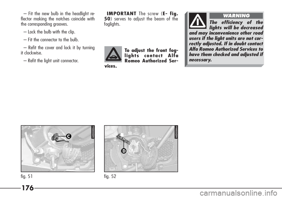
– Disconnect the connector (C- fig.
51) from the bulb.
– Release the clip and remove the bulb
(D- fig. 52).
A0D0080m
fig. 48
A0D0081m
fig. 49
A0D0082m
fig. 50
Page 177 of 272

176
– Fit the new bulb in the headlight re-
flector making the notches coincide with
the corresponding grooves.
– Lock the bulb with the clip.
– Fit the connector to the bulb.
– Refit the cover and lock it by turning
it clockwise.
– Refit the light unit connector.IMPORTANT The screw (E- fig.
50) serves to adjust the beam of the
foglights.
To adjust the front fog-
lights contact Alfa
Romeo Authorized Ser-
vices.
The efficiency of the
lights will be decreased
and may inconvenience other road
users if the light units are not cor-
rectly adjusted. If in doubt contact
Alfa Romeo Authorized Services to
have them checked and adjusted if
necessary.
WARNING
A0D0083m
fig. 51
A0D0084m
fig. 52
Page 178 of 272

177
SIDE DIRECTION INDICATORS
To replace a bulb (Type A, 5W amber):
– Push the transparent cover (fig. 53)
towards the rear of the car to compress
the tab (A-fig. 54). Release the catch
(B) and remove the unit.
– Turn the bulb holder (C-fig. 55)
counter-clockwise and remove it from the
transparent cover (D).– Withdraw the bulb (E) which is of the
pressure-fitted type and replace it.
– Insert the bulb-holder (C) in the
transparent cover (D).
Refit the unit firstly inserting the catch
(B-fig. 54) on the front part and then
pressing the rear part until the catch (A)
clicks into place.Take care not to dam-
age the bodywork or
the transparent cover
when removing the side direction
indicator unit.
P4C00057470PGSm472PGSm
fig. 53
471PGSm
fig. 54 fig. 55
Page 179 of 272

178
– Lower the lid (A-fig. 56) of the
boot trim corresponding with the light
concerned and remove the bulb holder
unit (B-fig. 57) releasing the retainer
catch (C).
– Remove and replace the bulb con-
cerned (spherical with bayonet coupling)
pushing gently and turning counter-clock-
wise (fig. 58):
(D) Reversing light bulb
(E) Rear fog guard bulb
(F) Sidelight bulb.GUARDS AND SIDELIGHTS
To replace the bulbs (Type B, 21W re-
versing light and rear fog guard, 5W side-
light):
– Open the boot.– Re-insert the bulb holder unit fasten-
ing it correctly in place using the retainer
catches (C-fig. 57).
– Shut the trim lid.
P4C00057611PGSm
fig. 56
606PGSm
fig. 57 fig. 58
607PGSm
Page 180 of 272

179
DIRECTION INDICATORS AND
SIDE LIGHTS/STOP LIGHTS
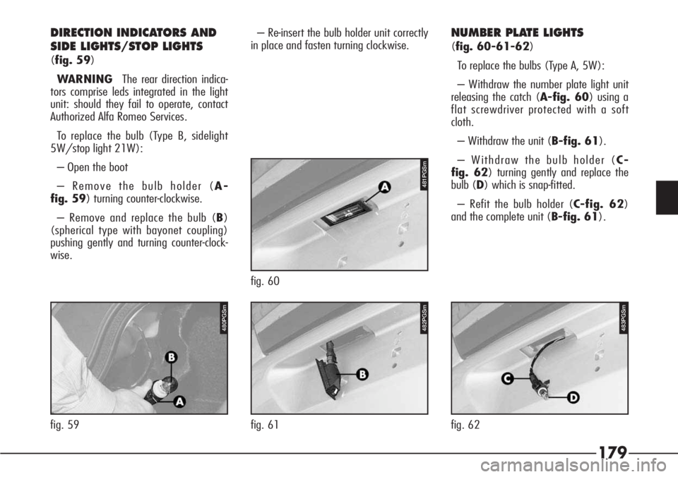
(fig. 59)
WARNING The rear direction indica-
tors comprise leds integrated in the light
unit: should they fail to operate, contact
Authorized Alfa Romeo Services.
To replace the bulb (Type B, sidelight
5W/stop light 21W):
– Open the boot
– Remove the bulb holder (A-
fig. 59) turning counter-clockwise.
– Remove and replace the bulb (B)
(spherical type with bayonet coupling)
pushing gently and turning counter-clock-
wise.– Re-insert the bulb holder unit correctly
in place and fasten turning clockwise.
NUMBER PLATE LIGHTS
(fig. 60-61-62)
To replace the bulbs (Type A, 5W):
– Withdraw the number plate light unit
releasing the catch (A-fig. 60) using a
flat screwdriver protected with a soft
cloth.
– Withdraw the unit (B-fig. 61).
– Withdraw the bulb holder (C-
fig. 62) turning gently and replace the
bulb (D) which is snap-fitted.
– Refit the bulb holder (C-fig. 62)
and the complete unit (B-fig. 61).
481PGSm
fig. 60
482PGSm
fig. 61
483PGSm
fig. 62
480PGSm
fig. 59