Alfa Romeo 166 2006 Owner handbook (in English)
Manufacturer: ALFA ROMEO, Model Year: 2006, Model line: 166, Model: Alfa Romeo 166 2006Pages: 272, PDF Size: 4.17 MB
Page 161 of 272
160
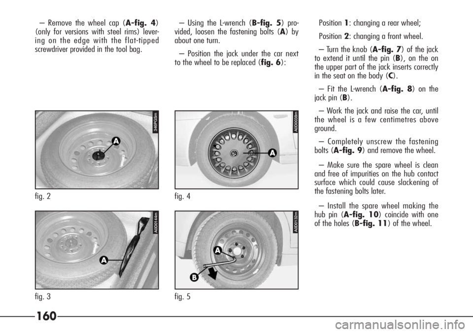
– Remove the wheel cap (A-fig. 4)
(only for versions with steel rims) lever-
ing on the edge with the flat-tipped
screwdriver provided in the tool bag.– Using the L-wrench (B-fig. 5) pro-
vided, loosen the fastening bolts (A) by
about one turn.
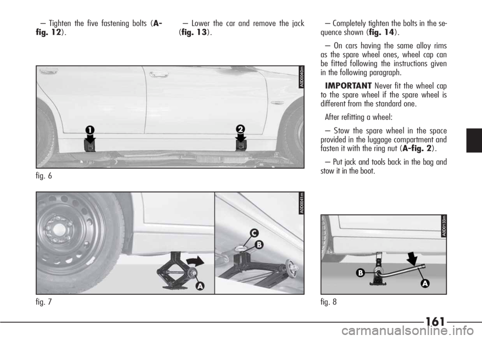
– Position the jack under the car next
to the wheel to be replaced (fig. 6):Position1: changing a rear wheel;
Position2: changing a front wheel.
– Turn the knob (A-fig. 7) of the jack
to extend it until the pin (B), on the on
the upper part of the jack inserts correctly
in the seat on the body (C).
– Fit the L-wrench (A-fig. 8) on the
jack pin (B).
– Work the jack and raise the car, until
the wheel is a few centimetres above
ground.
– Completely unscrew the fastening
bolts (A-fig. 9) and remove the wheel.
– Make sure the spare wheel is clean
and free of impurities on the hub contact
surface which could cause slackening of
the fastening bolts later.
– Install the spare wheel making the
hub pin (A-fig. 10) coincide with one
of the holes (B-fig. 11) of the wheel.
A0D0038m
fig. 4
A0D0132m
fig. 5
346PGSm
fig. 2
A0D0144m
fig. 3
Page 162 of 272
161
– Tighten the five fastening bolts (A-
fig. 12).– Lower the car and remove the jack
(fig. 13).– Completely tighten the bolts in the se-
quence shown (fig. 14).
– On cars having the same alloy rims
as the spare wheel ones, wheel cap can
be fitted following the instructions given
in the following paragraph.
IMPORTANTNever fit the wheel cap
to the spare wheel if the spare wheel is
different from the standard one.
After refitting a wheel:
– Stow the spare wheel in the space
provided in the luggage compartment and
fasten it with the ring nut (A-fig. 2).
– Put jack and tools back in the bag and
stow it in the boot.
fig. 7
A0D0041m
fig. 6
A0D0040m
A0D0133m
fig. 8
Page 163 of 272
162
REFITTING A NORMAL WHEEL
Refit the wheel as described below:
– Stop the car in such a position that it
is not dangerous for the traffic where it is
possible to change the wheel safely.
Where possible, park on a level, compact
surface.
– Engage the handbrake
– Engage 1st gear or reverse. For cars
with automatic gearbox set the lever to
positionP.
– Open the boot.
– Fold back the boot mat (A-fig. 1).– Take the tool bag (A-fig. 3) and
the spare wheel and bring them near to
the wheel to be changed.
– Remove the wheel cap (A-fig. 4)
(if present) levering on the edge with the
flat-tipped screwdriver provided in the tool
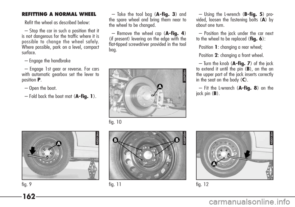
bag.– Using the L-wrench (B-fig. 5) pro-
vided, loosen the fastening bolts (A) by
about one turn.
– Position the jack under the car next
to the wheel to be replaced (fig. 6):
Position1: changing a rear wheel;
Position2: changing a front wheel.
– Turn the knob (A-fig. 7) of the jack
to extend it until the pin (B), on the on
the upper part of the jack inserts correctly
in the seat on the body (C).
– Fit the L-wrench (A-fig. 8) on the
jack pin (B).
392PGSm
fig. 10
1026PGSm
fig. 11
A0D0134m
fig. 9
A0D0135m
fig. 12
Page 164 of 272
163
– Work the jack and raise the car, until
the wheel is a few centimetres above
ground.
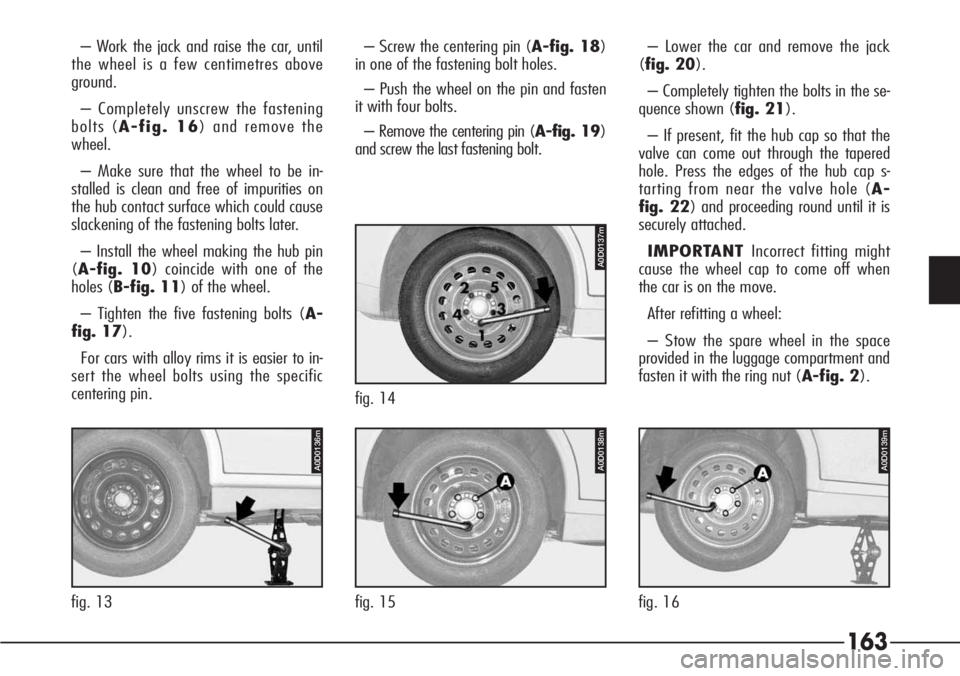
– Completely unscrew the fastening
bolts (A-fig. 16) and remove the
wheel.
– Make sure that the wheel to be in-
stalled is clean and free of impurities on
the hub contact surface which could cause
slackening of the fastening bolts later.
– Install the wheel making the hub pin
(A-fig. 10) coincide with one of the
holes (B-fig. 11) of the wheel.
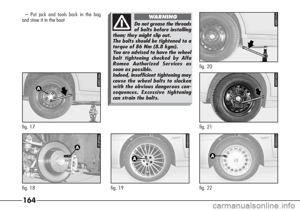
– Tighten the five fastening bolts (A-
fig. 17).
For cars with alloy rims it is easier to in-
sert the wheel bolts using the specific
centering pin.– Screw the centering pin (A-fig. 18)
in one of the fastening bolt holes.
– Push the wheel on the pin and fasten
it with four bolts.
– Remove the centering pin (A-fig. 19)
and screw the last fastening bolt.– Lower the car and remove the jack
(fig. 20).
– Completely tighten the bolts in the se-
quence shown (fig. 21).
– If present, fit the hub cap so that the
valve can come out through the tapered
hole. Press the edges of the hub cap s-
tarting from near the valve hole (A-
fig. 22) and proceeding round until it is
securely attached.
IMPORTANT Incorrect fitting might
cause the wheel cap to come off when
the car is on the move.
After refitting a wheel:
– Stow the spare wheel in the space
provided in the luggage compartment and
fasten it with the ring nut (A-fig. 2).
A0D0139m
fig. 16
A0D0138m
fig. 15
A0D0136m
fig. 13
A0D0137m
fig. 14
Page 165 of 272
164
– Put jack and tools back in the bag
and stow it in the boot
Do not grease the threads
of bolts before installing
them; they might slip out.
The bolts should be tightened to a
torque of 86 Nm (8.8 kgm).
You are advised to have the wheel
bolt tightening checked by Alfa
Romeo Authorized Services as
soon as possible.
Indeed, insufficient tightening may
cause the wheel bolts to slacken
with the obvious dangerous con-
sequences. Excessive tightening
can strain the bolts.
WARNING
A0D0053m
fig. 19
A0D0052m
fig. 22
612PGSm
fig. 18
A0D0140m
fig. 17
A0D0142m
fig. 21
A0D0141m
fig. 20
Page 166 of 272
165
GENERAL INSTRUCTIONS
– When a light is not working check
that the corresponding fuse is intact be-
fore replacing the bulb.
– For the location of fuses, refer to the
paragraph “In the event of a burnt fuse”
in this chapter.
– Before changing a bulb check the
contacts for oxidation.
– Burnt bulbs must be replaced with
others of the same type and power.
– Always check the height of the head-
light beam after changing a bulb to en-
sure they are safe.
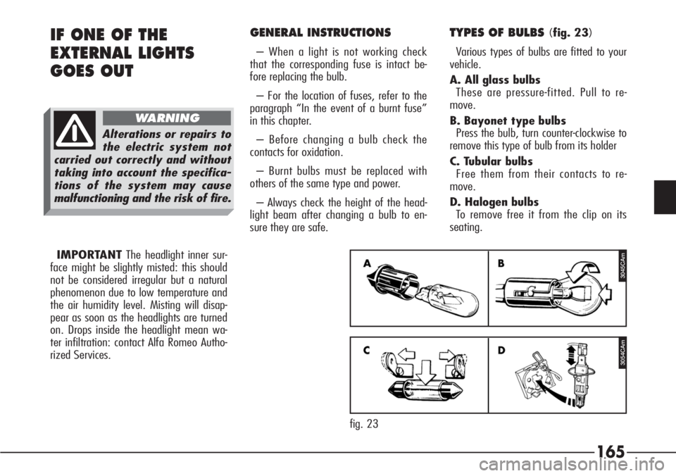
TYPES OF BULBS (fig. 23)
Various types of bulbs are fitted to your
vehicle.
A. All glass bulbs
These are pressure-fitted. Pull to re-
move.
B. Bayonet type bulbs
Press the bulb, turn counter-clockwise to
remove this type of bulb from its holder
C. Tubular bulbs
Free them from their contacts to re-
move.
D. Halogen bulbs
To remove free it from the clip on its
seating.IF ONE OF THE
EXTERNAL LIGHTS
GOES OUT
Alterations or repairs to
the electric system not
carried out correctly and without
taking into account the specifica-
tions of the system may cause
malfunctioning and the risk of fire.
WARNING
3045CAm
3054CAm
fig. 23 IMPORTANTThe headlight inner sur-
face might be slightly misted: this should
not be considered irregular but a natural
phenomenon due to low temperature and
the air humidity level. Misting will disap-
pear as soon as the headlights are turned
on. Drops inside the headlight mean wa-
ter infiltration: contact Alfa Romeo Autho-
rized Services.
Page 167 of 272
166
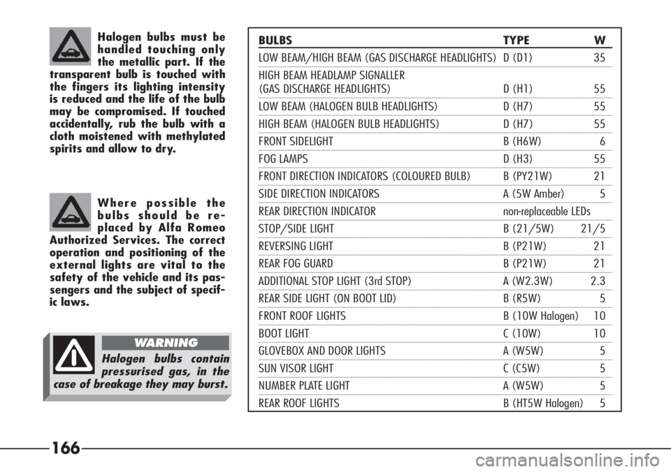
BULBS TYPE W
LOW BEAM/HIGH BEAM (GAS DISCHARGE HEADLIGHTS) D (D1) 35
HIGH BEAM HEADLAMP SIGNALLER
(GAS DISCHARGE HEADLIGHTS) D (H1) 55
LOW BEAM (HALOGEN BULB HEADLIGHTS) D (H7) 55
HIGH BEAM (HALOGEN BULB HEADLIGHTS) D (H7) 55
FRONT SIDELIGHT B (H6W) 6
FOG LAMPS D (H3) 55
FRONT DIRECTION INDICATORS (COLOURED BULB) B (PY21W) 21
SIDE DIRECTION INDICATORS A (5W Amber) 5
REAR DIRECTION INDICATOR non-replaceable LEDs
STOP/SIDE LIGHT B (21/5W) 21/5
REVERSING LIGHT B (P21W) 21
REAR FOG GUARD B (P21W) 21
ADDITIONAL STOP LIGHT (3rd STOP) A (W2.3W) 2.3
REAR SIDE LIGHT (ON BOOT LID) B (R5W) 5
FRONT ROOF LIGHTS B (10W Halogen) 10
BOOT LIGHT C (10W) 10
GLOVEBOX AND DOOR LIGHTS A (W5W) 5
SUN VISOR LIGHT C (C5W) 5
NUMBER PLATE LIGHT A (W5W) 5
REAR ROOF LIGHTS B (HT5W Halogen) 5
Halogen bulbs must be
handled touching only
the metallic part. If the
transparent bulb is touched with
the fingers its lighting intensity
is reduced and the life of the bulb
may be compromised. If touched
accidentally, rub the bulb with a
cloth moistened with methylated
spirits and allow to dry.
Where possible the
bulbs should be re-
placed by Alfa Romeo
Authorized Services. The correct
operation and positioning of the
external lights are vital to the
safety of the vehicle and its pas-
sengers and the subject of specif-
ic laws.
Halogen bulbs contain
pressurised gas, in the
case of breakage they may burst.
WARNING
Page 168 of 272
167
FRONT LIGHT UNITS - GAS
DISCHARGE HEADLIGHTS
(optional for versions/markets where
applicable)
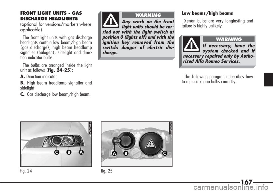
The front light units with gas discharge
headlights contain low beam/high beam
(gas discharge), high beam headlamp
signaller (halogen), sidelight and direc-
tion indicator bulbs.
The bulbs are arranged inside the light
unit as follows (fig. 24-25):
A.Direction indicator
B.High beam headlamp signaller and
sidelight
C.Gas discharge low beam/high beam.Low beams/high beams
Xenon bulbs are very longlasting and
failure is highly unlikely.
The following paragraph describes how
to replace xenon bulbs correctly.
Any work on the front
light units should be car-
ried out with the light switch at
position 0 (lights off) and with the
ignition key removed from the
switch: danger of electric dis-
charge.
WARNING
If necessary, have the
system checked and if
necessary repaired only by Autho-
rized Alfa Romeo Services.
WARNING
A0D0064m
fig. 24
A0D0065m
fig. 25
Page 169 of 272

168
To replace the bulb (Type D – D1,
35W):
– Remove the engine compartment cov-
er after turning the fastening pins.
– Remove the rubber cap (A-fig. 26)
by pulling the tab (B).– Release the clip (C- fig. 27).
– Remove the bulb (D- fig. 28) and
disconnect the snap-fitted connector (E).– Fit connector to new bulb.
– Fit the bulb in the headlight reflector
making the notch coincide with the corre-
sponding groove.
– Lock the bulb with the clip.
– Fit the rubber cap.
– Refit the engine compartment cover
and fasten turning the fastening pins. Xenon bulbs may only
be touched on the metal
part. If the glass bulb is
touched by the fingers, clean it
carefully with a clean cloth
moistened with methylated spirit
and allow to dry before refitting
the bulb.
Any work on the front
light units should be car-
ried out with the light switch at
position 0 (lights off) and with the
ignition key removed from the
switch: danger of electric dis-
charge.
WARNING
A0D0056m
fig. 26
A0D0057m
fig. 27
A0D0058m
fig. 28
Page 170 of 272

169
High beam headlamp signaller
To replace the bulb (Type D – H1,
55W):
– Remove the engine compartment cov-
er after turning the fastening pins.
– Turn counter-clockwise and remove
the direction indicator bulb holder (A-
fig. 29), without disconnecting the con-
nector to widen the working space.
– Remove the rubber cap (B) by
pulling the tab (C).– Disconnect the snap-fitted connector
(D- fig. 30) and release clip (E).
– Remove the bulb (F- fig. 31).– Fit new bulb in the headlight reflector
making the notches coincide with the cor-
responding grooves.
– Lock the bulb with the clip.
– Fit the connector to the bulb.
– Fit the rubber cap.
– Fit the direction indicator bulb holder
and lock it by turning it clockwise.
– Refit the engine compartment cover
and secure it by turning the fastening
pins.
A0D0059m
fig. 29
A0D0060m
fig. 30
A0D0061m
fig. 31