dashboard Alfa Romeo 166 2006 Owner handbook (in English)
[x] Cancel search | Manufacturer: ALFA ROMEO, Model Year: 2006, Model line: 166, Model: Alfa Romeo 166 2006Pages: 272, PDF Size: 4.17 MB
Page 57 of 272
56
Never travel with objects
on your lap, in front of
your chest or with a pipe, pencil,
etc. between your lips; injury may
result in the event of the air bag
being triggered.
WARNING
Always keep your hands
on the steering wheel rim
when driving, so that if the Air bag
is triggered, it can inflate without
meeting any obstacles which could
cause serious harm to you. Do not
drive with the body bent for-
wards, keep the seat back rest in
the erect position and lean your
back well against it.
WARNING
If the car has been stolen
or an attempt to steal it
has been made, if it has been sub-
jected to vandals or floods, have
the Air bag system checked by Alfa
Romeo Authorized Services.
WARNING
Do not wash the seat
back rest with pres-
surised water or steam (by hand
or at automatic seat washing sta-
tions).
WARNING
When the ignition key is
turned to the MAR posi-
tion, the warning light
F(with
passenger’s front air bag deacti-
vation switch in the ON position)
turns on and flashes for few sec-
onds to remind that passenger’s
air bag will be deployed in a crash,
after which it should go off.
WARNING
Please remember that
with the ignition key at
MAR, the air bags can be triggered
also on a stationary vehicle, if it is
bumped by another moving vehi-
cle. Therefore, even with the car
stationary, never allow children on
the front seat. On the other hand,
remember that with the car sta-
tionary and ignition key at STOP
no safety device (air bags or pre-
tensioners) will be triggered in the
event of an impact; in this case the
failure to trigger safety devices
should not be considered as a sys-
tem failure.
WARNING
Please don’t apply stickers
or other objects to the
steering wheel, to the air-bag cover
on the passenger's side or on the
side roof lining to the upholstery on
the roof side. Don’t place objects on
the dashboard passenger’s side
(such as mobile phones) because
they could tamper with the correct
opening of the passenger’s air-bag
and than cause serious injuries to
the vehicle occupants.
WARNING
Page 59 of 272
58
Sidelights
The sidelights are switched on by turn-
ing the knurled ring (A) from Oto
6.
The
3warning light on the instru-
ment panel will come on at the same
time.
Dipped-beam headlights
These are switched on by turning the
knurled ring (A) from
6to2.
Parking lights
When the pointer of the switch (A) cor-
responds with the
Fsymbol, the side
lights stay on regardless of the position of
the ignition key.
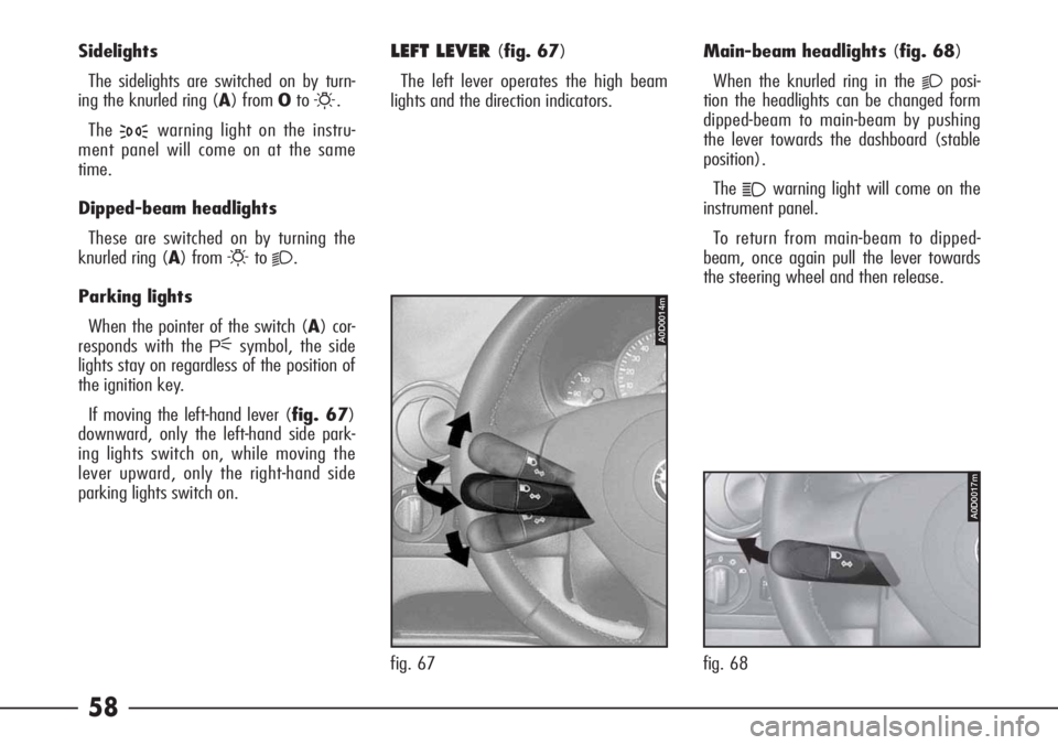
If moving the left-hand lever (fig. 67)
downward, only the left-hand side park-
ing lights switch on, while moving the
lever upward, only the right-hand side
parking lights switch on.Main-beam headlights (fig. 68)
When the knurled ring in the
2posi-
tion the headlights can be changed form
dipped-beam to main-beam by pushing
the lever towards the dashboard (stable
position).
The
1warning light will come on the
instrument panel.
To return from main-beam to dipped-
beam, once again pull the lever towards
the steering wheel and then release.
LEFT LEVER (fig. 67)
The left lever operates the high beam
lights and the direction indicators.
fig. 67
A0D0014m
A0D0017m
fig. 68
Page 82 of 272
81
The passenger compartment climate
control (heating, cooling and ventilation)
can be used in the following ways:
– manual climate control, by selecting
the functions using the control panel but-
tons;
– automatic climate control, managed
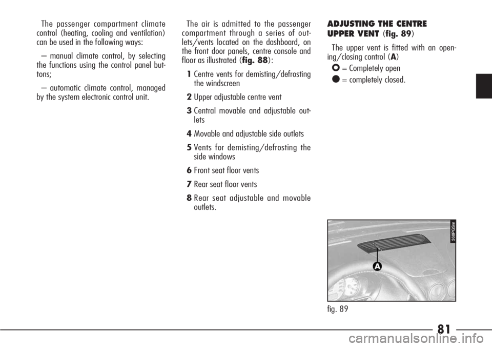
by the system electronic control unit.ADJUSTING THE CENTRE
UPPER VENT
(fig. 89)
The upper vent is fitted with an open-
ing/closing control (A)
O= Completely open
●= completely closed.
368PGSm
fig. 89 The air is admitted to the passenger
compartment through a series of out-
lets/vents located on the dashboard, on
the front door panels, centre console and
floor as illustrated (fig. 88):
1Centre vents for demisting/defrosting
the windscreen
2Upper adjustable centre vent
3Central movable and adjustable out-
lets
4Movable and adjustable side outlets
5Vents for demisting/defrosting the
side windows
6Front seat floor vents
7Rear seat floor vents
8Rear seat adjustable and movable
outlets.
Page 83 of 272

SIDE VENTS (fig. 93)
The front door panels contain fixed side
vents (A) for defrosting or demisting the
side windows.
422PGSm
fig. 93
338PGSm
fig. 92
82
ADJUSTABLE AND MOVABLE
OUTLETS
(fig. 90-91-92)
To open the round air vents, press on
the fins (A) in point (B).
The air flow is directed by turning the
outlets using the fins or changing their
slope.
Fig. 90: front seats (in the middle of
the dashboard)
fig. 91
421PGSm
A0D0028m
fig. 90Fig. 91: front seats (at the ends of the
dashboard)
Fig. 92: rear seats (on the centre con-
sole).
Page 89 of 272
88
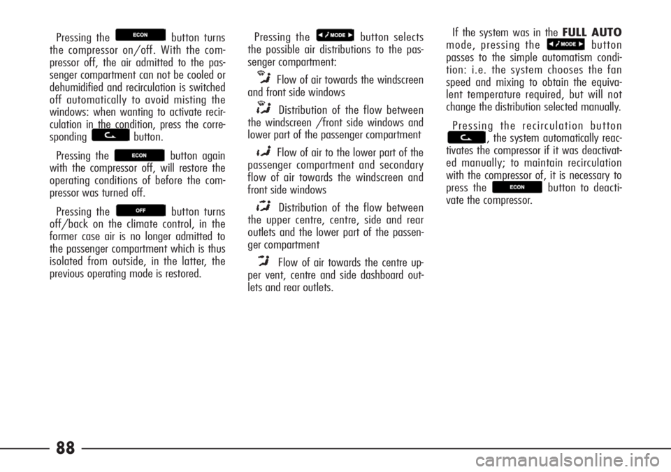
Pressing the button turns
the compressor on/off. With the com-
pressor off, the air admitted to the pas-
senger compartment can not be cooled or
dehumidified and recirculation is switched
off automatically to avoid misting the
windows: when wanting to activate recir-
culation in the condition, press the corre-
sponding button.
Pressing the button again
with the compressor off, will restore the
operating conditions of before the com-
pressor was turned off.
Pressing the button turns
off/back on the climate control, in the
former case air is no longer admitted to
the passenger compartment which is thus
isolated from outside, in the latter, the
previous operating mode is restored.Pressing the button selects
the possible air distributions to the pas-
senger compartment:
Flow of air towards the windscreen
and front side windows
Distribution of the flow between
the windscreen /front side windows and
lower part of the passenger compartment
Flow of air to the lower part of the
passenger compartment and secondary
flow of air towards the windscreen and
front side windows
Distribution of the flow between
the upper centre, centre, side and rear
outlets and the lower part of the passen-
ger compartment
Flow of air towards the centre up-
per vent, centre and side dashboard out-
lets and rear outlets.If the system was in the FULL AUTO
mode, pressing the button
passes to the simple automatism condi-
tion: i.e. the system chooses the fan
speed and mixing to obtain the equiva-
lent temperature required, but will not
change the distribution selected manually.
Pressing the recirculation button
, the system automatically reac-
tivates the compressor if it was deactivat-
ed manually; to maintain recirculation
with the compressor of, it is necessary to
press the button to deacti-
vate the compressor.
Page 95 of 272
94
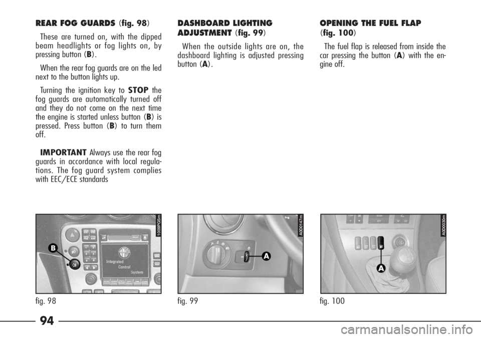
REAR FOG GUARDS (fig. 98)
These are turned on, with the dipped
beam headlights or fog lights on, by
pressing button (B).
When the rear fog guards are on the led
next to the button lights up.
Turning the ignition key to STOPthe
fog guards are automatically turned off
and they do not come on the next time
the engine is started unless button (B) is
pressed. Press button (B) to turn them
off.
IMPORTANT Always use the rear fog
guards in accordance with local regula-
tions. The fog guard system complies
with EEC/ECE standardsDASHBOARD LIGHTING
ADJUSTMENT
(fig. 99)
When the outside lights are on, the
dashboard lighting is adjusted pressing
button (A).
OPENING THE FUEL FLAP
(fig. 100)
The fuel flap is released from inside the
car pressing the button (A) with the en-
gine off.
A0D0147m
fig. 99
1009PGSm
fig. 98
fig. 100
A0D0030m
Page 97 of 272

96 INTERNAL FITTINGS
GLOVE BOX (fig. 108-109)
On the dashboard there is a key-lock-
able glovebox with light. The lock can be
opened/closed using the ignition key.
To open the glovebox pull lever (A).The compartment is lit by a courtesy
light (B) when it is open with the ignition
key at MAR.
429PGSm
fig. 108
430PGSm
fig. 109
Do not travel with the
glovebox open; it could
harm the passenger in the event of
an accident.
WARNING
Page 98 of 272

97
ODDMENTS COMPARTMENTS
ON THE DASHBOARD
Upper compartment
(fig. 110-111)
This is fitted with a lid. To open, press
and release the button (A). To close the
lid, simply lower it.Left side compartment (fig. 112)
On the lower side of the dashboard, at
the left of the steering wheel, there is an
oddments compartment (A).
436PGSm
fig. 112
600PGSm
fig. 110
601PGSm
fig. 111
COMPARTMENTS AND
POCKETS ON THE DOORS
(fig. 113-114)
Each door is fitted with a pocket.
fig. 113- Front doors
fig. 114- Rear doors.
438PGSm
fig. 114
437PGSm
fig. 113
Page 192 of 272
191
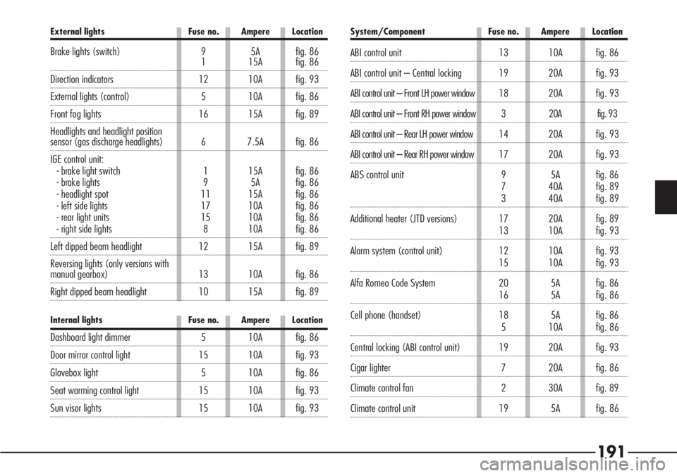
System/Component Fuse no. Ampere Location
ABI control unit 13 10A fig. 86
ABI control unit – Central locking 19 20A fig. 93
ABI control unit – Front LH power window 18 20Afig. 93
ABI control unit – Front RH power window 3 20A fig. 93
ABI control unit – Rear LH power window 14 20Afig. 93
ABI control unit – Rear RH power window 17 20Afig. 93
ABS control unit 9 5A fig. 86
7 40A fig. 89
3 40A fig. 89
Additional heater (JTD versions) 17 20A fig. 89
13 10A fig. 93
Alarm system (control unit) 12 10A fig. 93
15 10A fig. 93
Alfa Romeo Code System 20 5A fig. 86
16 5A fig. 86
Cell phone (handset) 18 5A fig. 86
5 10A fig. 86
Central locking (ABI control unit) 19 20A fig. 93
Cigar lighter 7 20A fig. 86
Climate control fan 2 30A fig. 89
Climate control unit 19 5A fig. 86
External lights Fuse no. Ampere Location
Brake lights (switch) 9 5A fig. 861 15A fig. 86
Direction indicators 12 10A fig. 93
External lights (control) 5 10A fig. 86
Front fog lights 16 15A fig. 89
Headlights and headlight position
sensor (gas discharge headlights) 6 7.5A fig. 86
IGE control unit:
- brake light switch 1 15A fig. 86
- brake lights 9 5A fig. 86
- headlight spot 11 15A fig. 86
- left side lights 17 10A fig. 86
- rear light units 15 10A fig. 86
- right side lights 8 10A fig. 86
Left dipped beam headlight 12 15A fig. 89
Reversing lights (only versions with
manual gearbox) 13 10A fig. 86
Right dipped beam headlight 10 15A fig. 89
Internal lights Fuse no. Ampere Location
Dashboard light dimmer 5 10A fig. 86
Door mirror control light 15 10A fig. 93
Glovebox light 5 10A fig. 86
Seat warming control light 15 10A fig. 93
Sun visor lights 15 10A fig. 93
Page 254 of 272
253
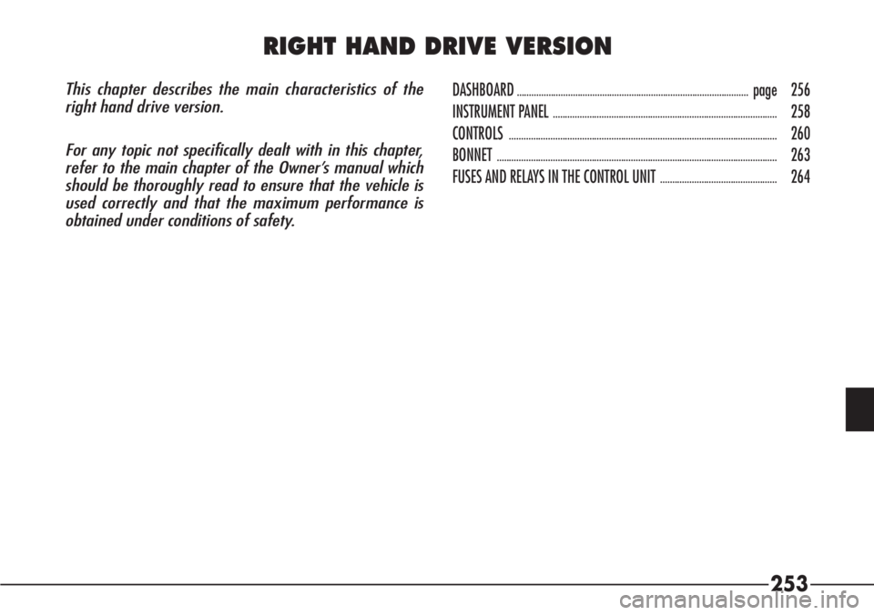
This chapter describes the main characteristics of the
right hand drive version.
For any topic not specifically dealt with in this chapter,
refer to the main chapter of the Owner’s manual which
should be thoroughly read to ensure that the vehicle is
used correctly and that the maximum performance is
obtained under conditions of safety.DASHBOARD...............................................................................................page 256
INSTRUMENT PANEL
............................................................................................258
CONTROLS
..............................................................................................................260
BONNET
...................................................................................................................263
FUSES AND RELAYS IN THE CONTROL UNIT
................................................264
RIGHT HAND DRIVE VERSION