headlight bulb Alfa Romeo 166 2006 Owner handbook (in English)
[x] Cancel search | Manufacturer: ALFA ROMEO, Model Year: 2006, Model line: 166, Model: Alfa Romeo 166 2006Pages: 272, PDF Size: 4.17 MB
Page 79 of 272
78
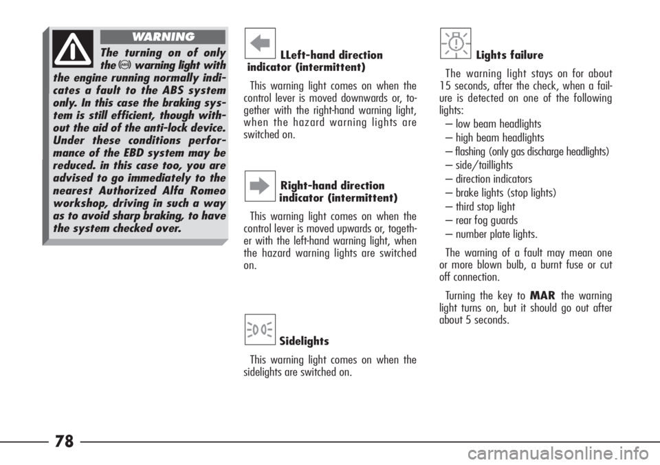
LLeft-hand direction
indicator (intermittent)
This warning light comes on when the
control lever is moved downwards or, to-
gether with the right-hand warning light,
when the hazard warning lights are
switched on. R
Sidelights
This warning light comes on when the
sidelights are switched on.3
Right-hand direction
indicator (intermittent)
This warning light comes on when the
control lever is moved upwards or, togeth-
er with the left-hand warning light, when
the hazard warning lights are switched
on.E
Lights failure
The warning light stays on for about
15 seconds, after the check, when a fail-
ure is detected on one of the following
lights:
– low beam headlights
– high beam headlights
– flashing (only gas discharge headlights)
– side/taillights
– direction indicators
– brake lights (stop lights)
– third stop light
– rear fog guards
– number plate lights.
The warning of a fault may mean one
or more blown bulb, a burnt fuse or cut
off connection.
Turning the key to MARthe warning
light turns on, but it should go out after
about 5 seconds.The turning on of only
the
>warning light with
the engine running normally indi-
cates a fault to the ABS system
only. In this case the braking sys-
tem is still efficient, though with-
out the aid of the anti-lock device.
Under these conditions perfor-
mance of the EBD system may be
reduced. in this case too, you are
advised to go immediately to the
nearest Authorized Alfa Romeo
workshop, driving in such a way
as to avoid sharp braking, to have
the system checked over.
WARNING
Page 113 of 272
112
AIMING LOW BEAM
HEADLAMPS FOR
LEFT/RIGHT CIRCULATION
(only for versions with gas discharge
headlamps)
On cars fitted with gas discharge head-
lamps (xenon bulbs)(optional for ver-
sions/markets where applicable) with
high lighting power, when passing from a
country with right circulation to one with
left circulation or vice versa it is necessary
to change the aiming of the low beams,
to optimise lighting of the edge of the
road and avoid glaring vehicles met.
IMPORTANT Contact Alfa Romeo Au-
thorised Services to have low beam head-
lamps correctly adjusted.
BEAM AIMING
(excluding versions with gas discharge
headlights)
The adjustment of the headlights is vital
to your safety and comfort and to that of
other road users.
The adjustment of the headlights is also
governed by precise regulations.
Contact Alfa Romeo Authorized Services
to have the headlights correctly adjusted.
When returning to the
country of origin, re-
member to change the low beam
aiming again.
WARNING
To have the position
checked and if neces-
sary adjusted, contact
Alfa Romeo Authorized Services.
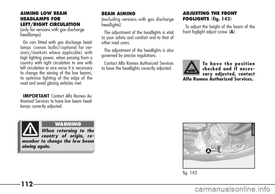
ADJUSTING THE FRONT
FOGLIGHTS
(fig. 143)
To adjust the height of the beam of the
front foglight adjust screw (A).
fig. 143
A0D0034m
Page 166 of 272
165
GENERAL INSTRUCTIONS
– When a light is not working check
that the corresponding fuse is intact be-
fore replacing the bulb.
– For the location of fuses, refer to the
paragraph “In the event of a burnt fuse”
in this chapter.
– Before changing a bulb check the
contacts for oxidation.
– Burnt bulbs must be replaced with
others of the same type and power.
– Always check the height of the head-
light beam after changing a bulb to en-
sure they are safe.
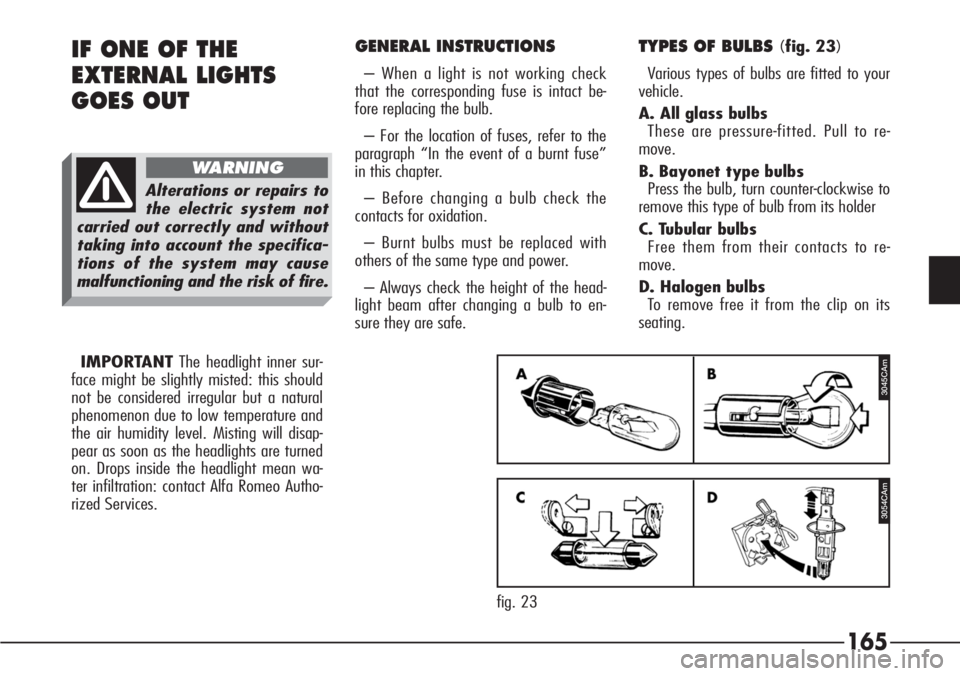
TYPES OF BULBS (fig. 23)
Various types of bulbs are fitted to your
vehicle.
A. All glass bulbs
These are pressure-fitted. Pull to re-
move.
B. Bayonet type bulbs
Press the bulb, turn counter-clockwise to
remove this type of bulb from its holder
C. Tubular bulbs
Free them from their contacts to re-
move.
D. Halogen bulbs
To remove free it from the clip on its
seating.IF ONE OF THE
EXTERNAL LIGHTS
GOES OUT
Alterations or repairs to
the electric system not
carried out correctly and without
taking into account the specifica-
tions of the system may cause
malfunctioning and the risk of fire.
WARNING
3045CAm
3054CAm
fig. 23 IMPORTANTThe headlight inner sur-
face might be slightly misted: this should
not be considered irregular but a natural
phenomenon due to low temperature and
the air humidity level. Misting will disap-
pear as soon as the headlights are turned
on. Drops inside the headlight mean wa-
ter infiltration: contact Alfa Romeo Autho-
rized Services.
Page 167 of 272
166
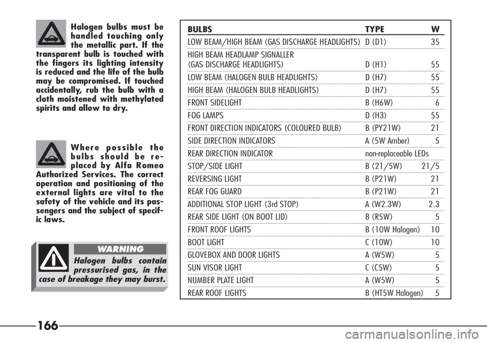
BULBS TYPE W
LOW BEAM/HIGH BEAM (GAS DISCHARGE HEADLIGHTS) D (D1) 35
HIGH BEAM HEADLAMP SIGNALLER
(GAS DISCHARGE HEADLIGHTS) D (H1) 55
LOW BEAM (HALOGEN BULB HEADLIGHTS) D (H7) 55
HIGH BEAM (HALOGEN BULB HEADLIGHTS) D (H7) 55
FRONT SIDELIGHT B (H6W) 6
FOG LAMPS D (H3) 55
FRONT DIRECTION INDICATORS (COLOURED BULB) B (PY21W) 21
SIDE DIRECTION INDICATORS A (5W Amber) 5
REAR DIRECTION INDICATOR non-replaceable LEDs
STOP/SIDE LIGHT B (21/5W) 21/5
REVERSING LIGHT B (P21W) 21
REAR FOG GUARD B (P21W) 21
ADDITIONAL STOP LIGHT (3rd STOP) A (W2.3W) 2.3
REAR SIDE LIGHT (ON BOOT LID) B (R5W) 5
FRONT ROOF LIGHTS B (10W Halogen) 10
BOOT LIGHT C (10W) 10
GLOVEBOX AND DOOR LIGHTS A (W5W) 5
SUN VISOR LIGHT C (C5W) 5
NUMBER PLATE LIGHT A (W5W) 5
REAR ROOF LIGHTS B (HT5W Halogen) 5
Halogen bulbs must be
handled touching only
the metallic part. If the
transparent bulb is touched with
the fingers its lighting intensity
is reduced and the life of the bulb
may be compromised. If touched
accidentally, rub the bulb with a
cloth moistened with methylated
spirits and allow to dry.
Where possible the
bulbs should be re-
placed by Alfa Romeo
Authorized Services. The correct
operation and positioning of the
external lights are vital to the
safety of the vehicle and its pas-
sengers and the subject of specif-
ic laws.
Halogen bulbs contain
pressurised gas, in the
case of breakage they may burst.
WARNING
Page 168 of 272
167
FRONT LIGHT UNITS - GAS
DISCHARGE HEADLIGHTS
(optional for versions/markets where
applicable)
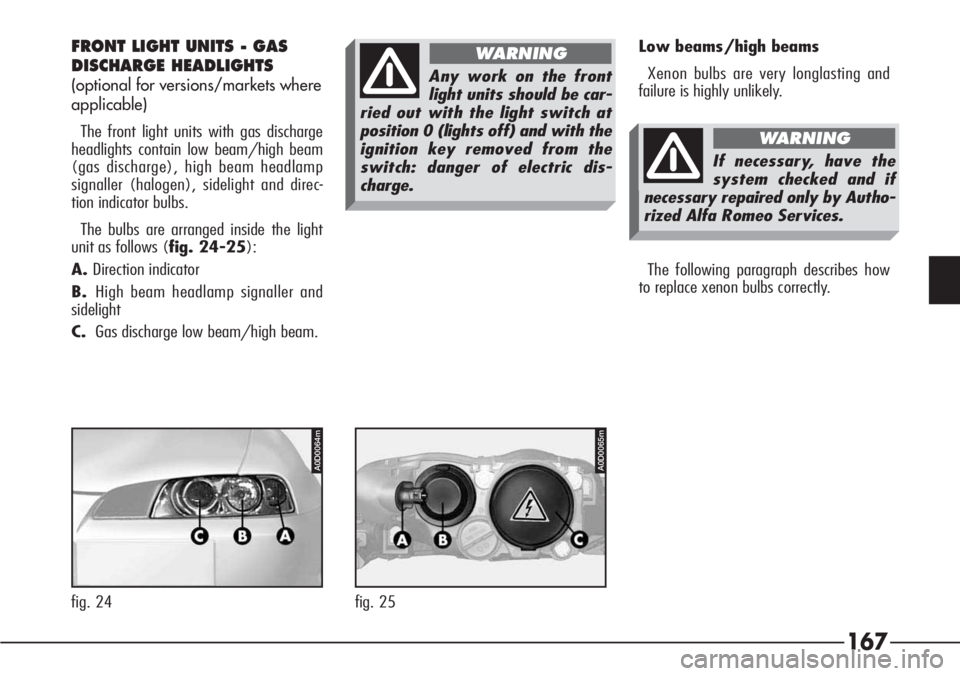
The front light units with gas discharge
headlights contain low beam/high beam
(gas discharge), high beam headlamp
signaller (halogen), sidelight and direc-
tion indicator bulbs.
The bulbs are arranged inside the light
unit as follows (fig. 24-25):
A.Direction indicator
B.High beam headlamp signaller and
sidelight
C.Gas discharge low beam/high beam.Low beams/high beams
Xenon bulbs are very longlasting and
failure is highly unlikely.
The following paragraph describes how
to replace xenon bulbs correctly.
Any work on the front
light units should be car-
ried out with the light switch at
position 0 (lights off) and with the
ignition key removed from the
switch: danger of electric dis-
charge.
WARNING
If necessary, have the
system checked and if
necessary repaired only by Autho-
rized Alfa Romeo Services.
WARNING
A0D0064m
fig. 24
A0D0065m
fig. 25
Page 169 of 272

168
To replace the bulb (Type D – D1,
35W):
– Remove the engine compartment cov-
er after turning the fastening pins.
– Remove the rubber cap (A-fig. 26)
by pulling the tab (B).– Release the clip (C- fig. 27).
– Remove the bulb (D- fig. 28) and
disconnect the snap-fitted connector (E).– Fit connector to new bulb.
– Fit the bulb in the headlight reflector
making the notch coincide with the corre-
sponding groove.
– Lock the bulb with the clip.
– Fit the rubber cap.
– Refit the engine compartment cover
and fasten turning the fastening pins. Xenon bulbs may only
be touched on the metal
part. If the glass bulb is
touched by the fingers, clean it
carefully with a clean cloth
moistened with methylated spirit
and allow to dry before refitting
the bulb.
Any work on the front
light units should be car-
ried out with the light switch at
position 0 (lights off) and with the
ignition key removed from the
switch: danger of electric dis-
charge.
WARNING
A0D0056m
fig. 26
A0D0057m
fig. 27
A0D0058m
fig. 28
Page 170 of 272

169
High beam headlamp signaller
To replace the bulb (Type D – H1,
55W):
– Remove the engine compartment cov-
er after turning the fastening pins.
– Turn counter-clockwise and remove
the direction indicator bulb holder (A-
fig. 29), without disconnecting the con-
nector to widen the working space.
– Remove the rubber cap (B) by
pulling the tab (C).– Disconnect the snap-fitted connector
(D- fig. 30) and release clip (E).
– Remove the bulb (F- fig. 31).– Fit new bulb in the headlight reflector
making the notches coincide with the cor-
responding grooves.
– Lock the bulb with the clip.
– Fit the connector to the bulb.
– Fit the rubber cap.
– Fit the direction indicator bulb holder
and lock it by turning it clockwise.
– Refit the engine compartment cover
and secure it by turning the fastening
pins.
A0D0059m
fig. 29
A0D0060m
fig. 30
A0D0061m
fig. 31
Page 172 of 272

171
Front direction indicators
To replace the bulb (Type B – PY21W,
21W, coloured):
– Remove the engine compartment cov-
er after turning the fastening pins.
– Turn counter-clockwise and remove
the bulb holder (A- fig. 35) without
disconnecting the connector.
– Remove the bulb (B- fig. 36) from
the bulb holder, pushing it slightly and
turning it counter-clockwise.– Fit the new bulb into the bulb holder,
pushing it slightly and turning it clock-
wise.
– Fit the bulb holder and lock it by turn-
ing it clockwise.
– Refit the engine compartment cover
and secure it by turning the fastening
pins.FRONT LIGHT UNITS –
HALOGEN BULB HEADLIGHTS
(optional for versions/markets where
applicable)
The front light units with halogen bulb
headlights contain low beam, high beam,
sidelight and direction indicator bulbs.
The bulbs are arranged inside the light
unit as follows (fig. 37-38):
A.Direction indicator
B.High beam headlight and sidelight
C.Low beam headlight.
A0D0070m
fig. 35
A0D0071m
fig. 36
A0D0054m
fig. 37
Page 173 of 272

172
Low beam headlights
To replace the bulb (Type D – H7,
55W):
– Remove the engine compartment cov-
er after turning the fastening pins.
– Remove the rubber cap (A- fig.
39) by pulling the tab (B).
– Disconnect the snap-fitted connector
(C- fig. 40).
–- Release the clip (D).
– Remove the bulb (E- fig. 41).– Fit the bulb in the headlight reflector
making the notch coincide with the corre-
sponding groove.
– Lock the bulb with the clip.
– Fit the connector to the new bulb.
– Fit the rubber cap.– Refit the engine compartment cover
and secure it by turning the fastening
pins.
A0D0036m
fig. 38
A0D0072m
fig. 39
A0D0074m
fig. 41
A0D0073m
fig. 40
Page 174 of 272

173
High beam headlights
To replace the bulb (Type D – H7,
55W):
– Remove the engine compartment cov-
er after turning the fastening pins.
– Turn counter-clockwise and remove
the direction indicator bulb holder (A-
fig. 42) without disconnecting the con-
nector to widen the working space.
– Remove the rubber cap (B) by
pulling the tab (C).– Disconnect the snap-fitted connector
(D- fig. 43) and release the clip (E).
– Remove the bulb (F- fig. 44).– Fit the new bulb in the headlight re-
flector making the notches coincide with
the corresponding grooves.
– Lock the bulb with the clip.
– Fit the connector to the bulb.
– Fit the rubber cap.
– Fit the direction indicator bulb holder
and lock it by turning it clockwise.
– Refit the engine compartment cover
and secure it by turning the fastening
pins.
A0D0075m
fig. 42
A0D0076m
fig. 43
A0D0077m
fig. 44