lock Alfa Romeo 4C 2014 Owner handbook (in English)
[x] Cancel search | Manufacturer: ALFA ROMEO, Model Year: 2014, Model line: 4C, Model: Alfa Romeo 4C 2014Pages: 190, PDF Size: 7.87 MB
Page 34 of 190
14) 15)
Automatic deactivation
The device is automatically switched off
in the following cases:
ŌØÆif the ABS or ESC systems intervene;
ŌØÆ with the car speed below the set
limit;
ŌØÆ in the event of system failure.
WARNING
14) When driving with device active,
do not press the "N" button on
the transmission control panel.
15) If operation of the device is faulty or in the case of failure, turn
ring nut A fig. 24 to Oand contact
a dedicated Alfa Romeo
Dealership.
ROOF LIGHTOperation
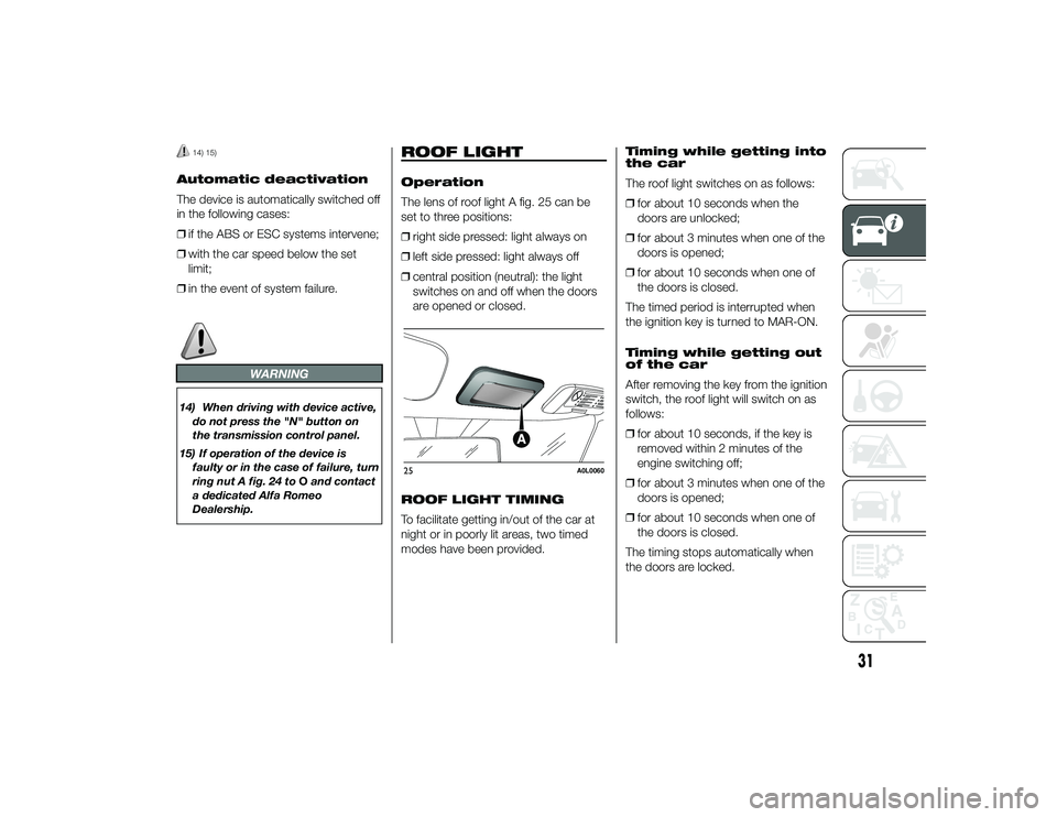
The lens of roof light A fig. 25 can be
set to three positions:
ŌØÆ right side pressed: light always on
ŌØÆ left side pressed: light always off
ŌØÆ central position (neutral): the light
switches on and off when the doors
are opened or closed.
ROOF LIGHT TIMING
To facilitate getting in/out of the car at
night or in poorly lit areas, two timed
modes have been provided. Timing while getting into
the car
The roof light switches on as follows:
ŌØÆ
for about 10 seconds when the
doors are unlocked;
ŌØÆ for about 3 minutes when one of the
doors is opened;
ŌØÆ for about 10 seconds when one of
the doors is closed.
The timed period is interrupted when
the ignition key is turned to MAR-ON.
Timing while getting out
of the car
After removing the key from the ignition
switch, the roof light will switch on as
follows:
ŌØÆ for about 10 seconds, if the key is
removed within 2 minutes of the
engine switching off;
ŌØÆ for about 3 minutes when one of the
doors is opened;
ŌØÆ for about 10 seconds when one of
the doors is closed.
The timing stops automatically when
the doors are locked.25
A0L0060
31
24-9-2013 11:49 Pagina 31
Page 35 of 190
CONTROLSHAZARD WARNING
LIGHTS
Operation
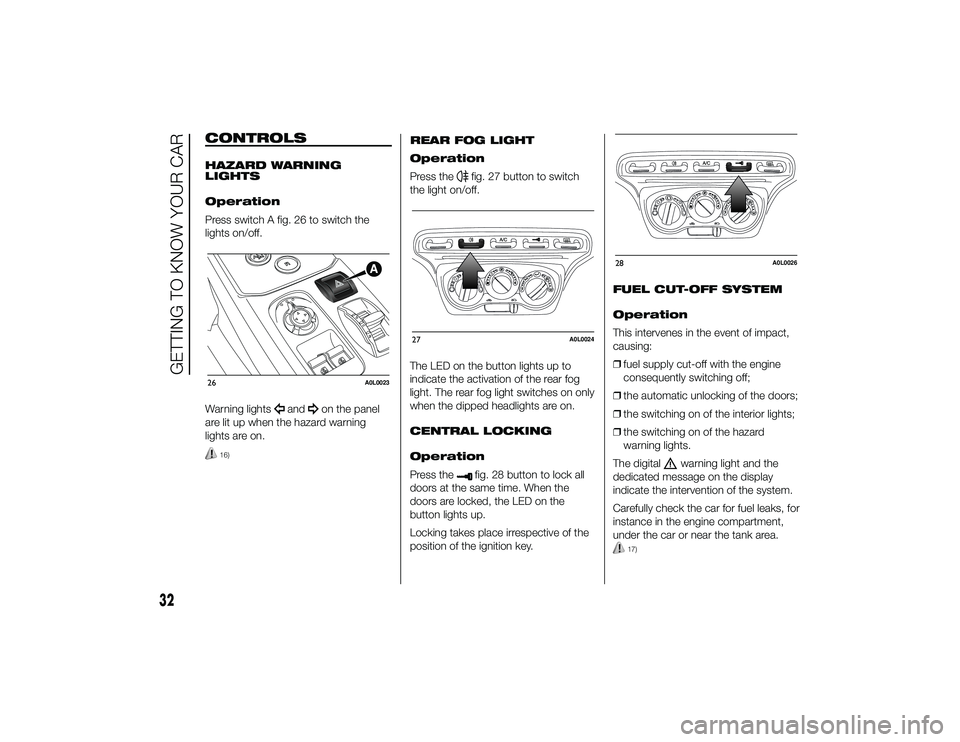
Press switch A fig. 26 to switch the
lights on/off.
Warning lights
and
on the panel
are lit up when the hazard warning
lights are on.
16)
REAR FOG LIGHT
Operation
Press the
fig. 27 button to switch
the light on/off.
The LED on the button lights up to
indicate the activation of the rear fog
light. The rear fog light switches on only
when the dipped headlights are on.
CENTRAL LOCKING
Operation
Press thefig. 28 button to lock all
doors at the same time. When the
doors are locked, the LED on the
button lights up.
Locking takes place irrespective of the
position of the ignition key. FUEL CUT-OFF SYSTEM
Operation
This intervenes in the event of impact,
causing:
ŌØÆ
fuel supply cut-off with the engine
consequently switching off;
ŌØÆ the automatic unlocking of the doors;
ŌØÆ the switching on of the interior lights;
ŌØÆ the switching on of the hazard
warning lights.
The digital
warning light and the
dedicated message on the display
indicate the intervention of the system.
Carefully check the car for fuel leaks, for
instance in the engine compartment,
under the car or near the tank area.
17)
26
A0L0023
27
A0L0024
28
A0L0026
32
GETTING TO KNOW YOUR CAR
24-9-2013 11:49 Pagina 32
Page 36 of 190

After a collision, turn the ignition key to
STOP to prevent the battery from
running down.
To restore the correct operation of the
car, proceed as follows:
ŌØÆbring the left exterior light control
stalk to central position (neutral);
ŌØÆ turn the ignition key to the MAR-ON
position;
ŌØÆ activate the right direction indicator;
ŌØÆ deactivate the right direction
indicator;
ŌØÆ activate the left direction indicator;
ŌØÆ deactivate the left direction indicator;
ŌØÆ activate the right direction indicator;
ŌØÆ deactivate the right direction
indicator;
ŌØÆ activate the left direction indicator;
ŌØÆ deactivate the left direction indicator;
ŌØÆ turn the ignition key to the STOP
position;
ŌØÆ turn the ignition key to the MAR-ON
position.
WARNING
16) The use of hazard warning lights
is governed by the Highway Code
of the country you are driving in:
comply with legal requirements.
17) If, after an impact, you smell fuel or notice leaks from the fuel
system, do not reactivate the
system to avoid the risk of fire.
INTERIOR FITTINGSSTORAGE
COMPARTMENTS
Front
For versions/markets, where provided,
the car features a storage compartment
A fig. 29 on the dashboard.
Rear
This is located at the centre of the rear
partition, easily accessible from the 2
seats. To access it, press button A fig.
30 and release clasp B. There is a
lock in button A, permitting the storage
compartment to be locked using a
specific key.
On some versions, the storage
compartment is replaced with a mesh
pocket fig. 31.29
A0L0159
33
24-9-2013 11:49 Pagina 33
Page 39 of 190
DOORSCENTRAL DOOR
LOCKING/UNLOCKING
Locking doors from the
outside
With the doors closed, press thebutton on the key or turn the metal
insert (located inside the key) in the
door lock.
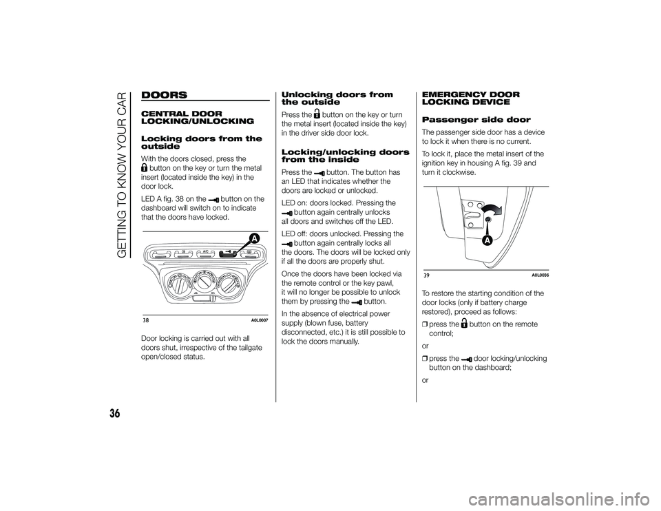
LED A fig. 38 on the
button on the
dashboard will switch on to indicate
that the doors have locked.
Door locking is carried out with all
doors shut, irrespective of the tailgate
open/closed status. Unlocking doors from
the outside
Press the
button on the key or turn
the metal insert (located inside the key)
in the driver side door lock.
Locking/unlocking doors
from the inside
Press thebutton. The button has
an LED that indicates whether the
doors are locked or unlocked.
LED on: doors locked. Pressing the
button again centrally unlocks
all doors and switches off the LED.
LED off: doors unlocked. Pressing thebutton again centrally locks all
the doors. The doors will be locked only
if all the doors are properly shut.
Once the doors have been locked via
the remote control or the key pawl,
it will no longer be possible to unlock
them by pressing the
button.
In the absence of electrical power
supply (blown fuse, battery
disconnected, etc.) it is still possible to
lock the doors manually. EMERGENCY DOOR
LOCKING DEVICE
Passenger side door
The passenger side door has a device
to lock it when there is no current.
To lock it, place the metal insert of the
ignition key in housing A fig. 39 and
turn it clockwise.
To restore the starting condition of the
door locks (only if battery charge
restored), proceed as follows:
ŌØÆ
press the
button on the remote
control;
or
ŌØÆ press thedoor locking/unlocking
button on the dashboard;
or
38
A0L0007
39
A0L0036
36
GETTING TO KNOW YOUR CAR
24-9-2013 11:49 Pagina 36
Page 40 of 190
ŌØÆintroduce the metal insert of the
ignition key in the front door pawl;
or
ŌØÆ pull the internal door handle.
Door opening/closing
mechanism initialisation
If the battery is disconnected or the
protection fuse blows, the door
opening/closing mechanism must be
initialised as follows:
ŌØÆ close all the doors;
ŌØÆ press the
button on the key or the
door locking/unlocking button on
the dashboard;
ŌØÆ press the
button on the key or the
door locking/unlocking button on
the dashboard.
ELECTRIC WINDOWS
IN BRIEF
These operate when the ignition key
is turned to MAR-ON and for about
three minutes after the ignition key is
turned to STOP or removed unless
one of the doors is opened.
The buttons are located on the
central tunnel.
20)
Operation
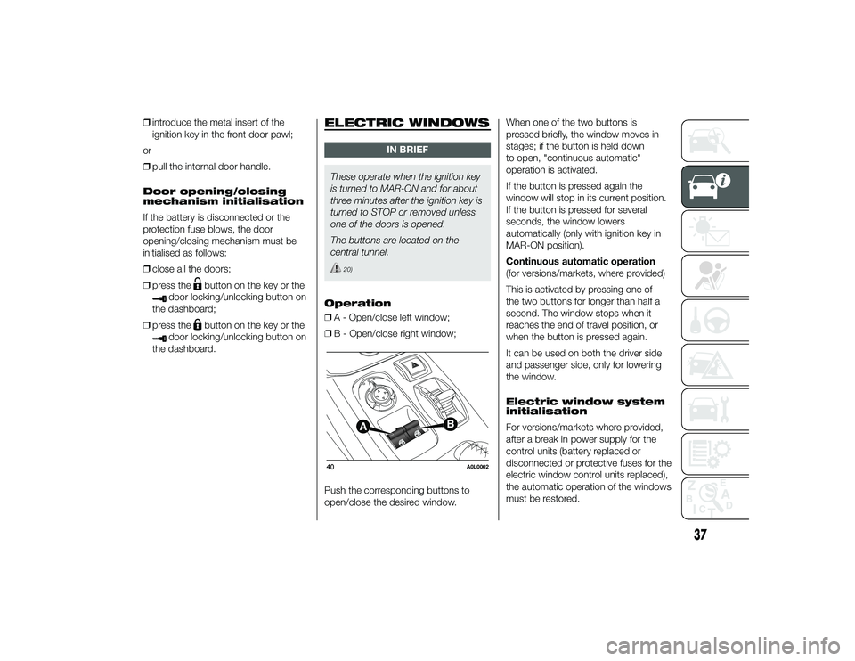
ŌØÆ A - Open/close left window;
ŌØÆ B - Open/close right window;
Push the corresponding buttons to
open/close the desired window. When one of the two buttons is
pressed briefly, the window moves in
stages; if the button is held down
to open, "continuous automatic"
operation is activated.
If the button is pressed again the
window will stop in its current position.
If the button is pressed for several
seconds, the window lowers
automatically (only with ignition key in
MAR-ON position).
Continuous automatic operation
(for versions/markets, where provided)
This is activated by pressing one of
the two buttons for longer than half a
second. The window stops when it
reaches the end of travel position, or
when the button is pressed again.
It can be used on both the driver side
and passenger side, only for lowering
the window.
Electric window system
initialisation
For versions/markets where provided,
after a break in power supply for the
control units (battery replaced or
disconnected or protective fuses for the
electric window control units replaced),
the automatic operation of the windows
must be restored.40
A0L0002
37
24-9-2013 11:49 Pagina 37
Page 42 of 190
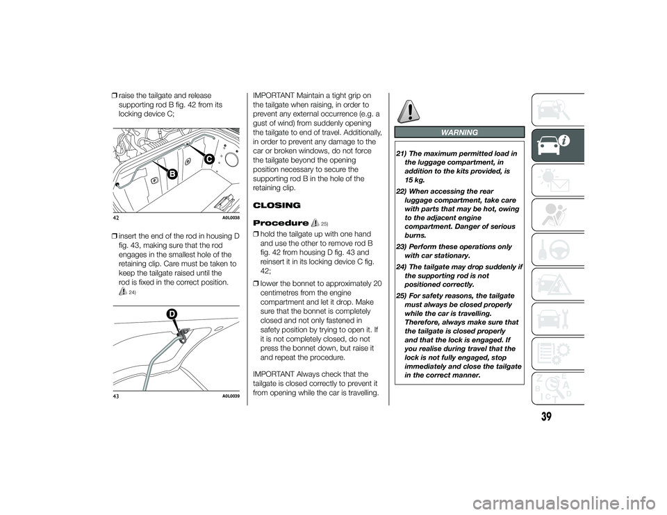
ŌØÆraise the tailgate and release
supporting rod B fig. 42 from its
locking device C;
ŌØÆ insert the end of the rod in housing D
fig. 43, making sure that the rod
engages in the smallest hole of the
retaining clip. Care must be taken to
keep the tailgate raised until the
rod is fixed in the correct position.
24)
IMPORTANT Maintain a tight grip on
the tailgate when raising, in order to
prevent any external occurrence (e.g. a
gust of wind) from suddenly opening
the tailgate to end of travel. Additionally,
in order to prevent any damage to the
car or broken windows, do not force
the tailgate beyond the opening
position necessary to secure the
supporting rod B in the hole of the
retaining clip.
CLOSING
Procedure
25)
ŌØÆhold the tailgate up with one hand
and use the other to remove rod B
fig. 42 from housing D fig. 43 and
reinsert it in its locking device C fig.
42;
ŌØÆ lower the bonnet to approximately 20
centimetres from the engine
compartment and let it drop. Make
sure that the bonnet is completely
closed and not only fastened in
safety position by trying to open it. If
it is not completely closed, do not
press the bonnet down, but raise it
and repeat the procedure.
IMPORTANT Always check that the
tailgate is closed correctly to prevent it
from opening while the car is travelling.
WARNING
21) The maximum permitted load in the luggage compartment, in
addition to the kits provided, is
15 kg.
22) When accessing the rear luggage compartment, take care
with parts that may be hot, owing
to the adjacent engine
compartment. Danger of serious
burns.
23) Perform these operations only with car stationary.
24) The tailgate may drop suddenly if the supporting rod is not
positioned correctly.
25) For safety reasons, the tailgate must always be closed properly
while the car is travelling.
Therefore, always make sure that
the tailgate is closed properly
and that the lock is engaged. If
you realise during travel that the
lock is not fully engaged, stop
immediately and close the tailgate
in the correct manner.
42
A0L0038
43
A0L0039
39
24-9-2013 11:49 Pagina 39
Page 43 of 190
HEADLIGHTSLIGHT BEAM DIRECTION
The correct orientation of the headlights
is important for the driver's comfort
and safety as well as for all other road
users. This is also covered by a specific
rule of the highway code.
The headlights must be correctly
directed to ensure the best visibility
conditions for all drivers. Contact a
dedicated Alfa Romeo Dealership to
have the headlights checked and
adjusted.
ADJUSTING THE
HEADLIGHTS ABROAD
The dipped beam headlights are
aligned to comply with the regulations
of the country of purchase. When in
countries where you drive on the other
side of the road, you need to alter
the beam direction in order not
to dazzle the vehicles travelling in the
opposite direction, proceeding as
follows:
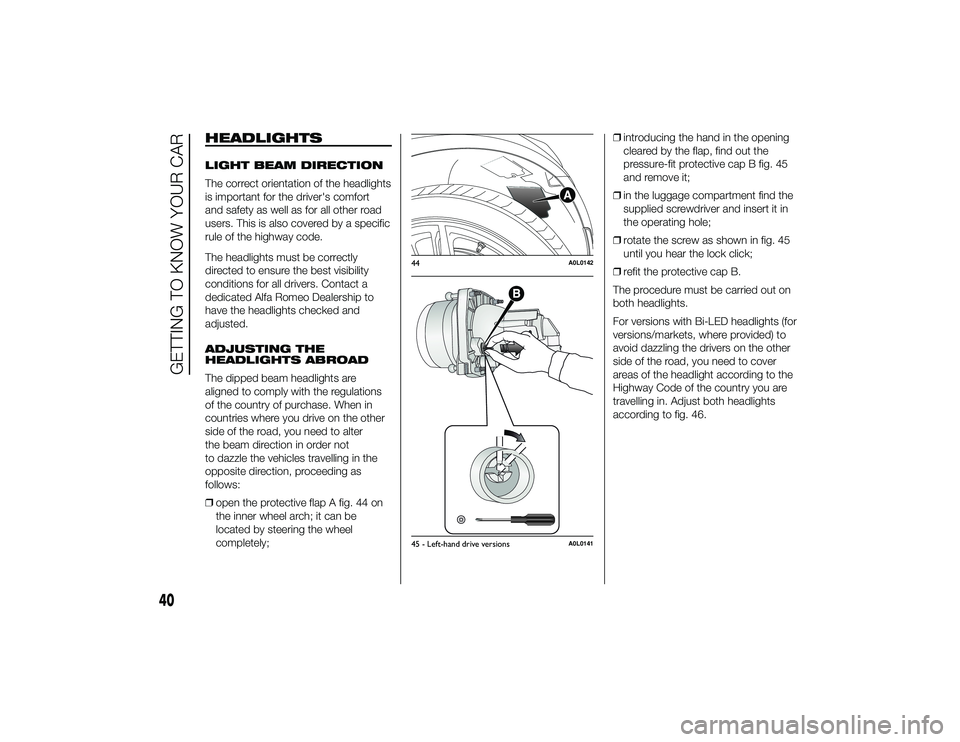
ŌØÆopen the protective flap A fig. 44 on
the inner wheel arch; it can be
located by steering the wheel
completely; ŌØÆ
introducing the hand in the opening
cleared by the flap, find out the
pressure-fit protective cap B fig. 45
and remove it;
ŌØÆ in the luggage compartment find the
supplied screwdriver and insert it in
the operating hole;
ŌØÆ rotate the screw as shown in fig. 45
until you hear the lock click;
ŌØÆ refit the protective cap B.
The procedure must be carried out on
both headlights.
For versions with Bi-LED headlights (for
versions/markets, where provided) to
avoid dazzling the drivers on the other
side of the road, you need to cover
areas of the headlight according to the
Highway Code of the country you are
travelling in. Adjust both headlights
according to fig. 46.
44
A0L0142
45 - Left-hand drive versions
A0L0141
40
GETTING TO KNOW YOUR CAR
24-9-2013 11:49 Pagina 40
Page 45 of 190
SYSTEM INTERVENTION
This is indicated by the flashing of the
warning light on the instrument
panel, to inform the driver that the car is
in critical stability and grip conditions.
ABS
This system, which is an integral part of
the braking system, prevents one or
more wheels from locking and slipping
in all road surface conditions,
irrespective of the intensity of the
braking action, ensuring that the car
can be controlled even during
emergency braking and optimising
stopping distances.
The system intervenes when braking
and the wheels are about to lock,
typically in emergency braking or
low-grip conditions, when locking may
be more frequent.
The system also improves control and
stability of the car when braking on a
surface where the grip of the left and
right wheels varies, or on corners.31) 32) 33) 34) 35) 36) 37)
System intervention
A slight pulsing of the brake pedal and
noise indicates the intervention of the
ABS: this is completely normal when
the system intervenes.
EBD SYSTEM
The EBD system is an integral part of
the ABS system and intervenes during
braking, distributing the brake force
optimally between front and rear
wheels.
This guarantees greater braking stability
for the vehicle, preventing sudden
locking of the rear wheels and
the consequent instability of the vehicle.
CBC (Cornering Brake
Control) SYSTEM
The system acts when braking on
corners, optimising the distribution of
brake pressure on the four wheels: the
system prevents the wheels on the
inside of the corner (less affected by the
weight of the car) from locking,
ensuring better stability and direction
for the car. DTC (Drag Torque
Control) SYSTEM
This is an integral part of the ABS
system and intervenes in the case of
sudden downshifting, or during braking
when the ABS intervenes, restoring
torque to the engine and thus
preventing excessive drag at the drive
wheels, which may lead the wheels
to lock and a loss of car stability, above
all in low-grip conditions.
ASR (AntiSlip
Regulation) SYSTEM
29) 30) 38) 39) 40)
This is an integral part of the ESC
system and automatically operates in
the event of one or both drive wheels
slipping, loss of grip on wet roads
(aquaplaning) and acceleration
on slippery, snowy or icy roads, etc.
Depending on the slipping conditions,
two different control systems are
activated:
ŌØÆ
if the slipping involves both drive
wheels, the ASR system intervenes,
reducing the power transmitted by
the engine;
ŌØÆ if the slipping only involves one of the
drive wheels, it also intervenes
automatically, braking the wheel that
is slipping.
42
GETTING TO KNOW YOUR CAR
24-9-2013 11:49 Pagina 42
Page 62 of 190
KNOWING THE INSTRUMENT PANEL
This section of the booklet gives you all
the information you need to
understand, interpret and use the
instrument panel correctly.CONTROL PANEL AND
INSTRUMENTS ............................... 60
SETUP MENU ................................. 62
MENU OPTIONS ............................. 64
TRIP COMPUTER ........................... 68
WARNING LIGHTS AND
MESSAGES .................................... 71
- LOW BRAKE FLUID / HANDBRAKE
ENGAGED .......................................... 71
- EBD FAILURE .................................. 72
- AIRBAG FAILURE ............................. 72
- SEAT BELTS NOT FASTENED .......... 72
- ABS FAILURE ................................... 73
- PASSENGER AIRBAG
DEACTIVATED .................................... 74
- INJECTION/EOBD SYSTEM
FAILURE ............................................. 75
- TPMS ............................................... 76
- ELECTRONIC STABILITY CONTROL
(ESC) SYSTEM ................................... 77
- ASR FUNCTION DEACTIVATED
WARNING LIGHT ............................... 77
- SIDE LIGHTS AND DIPPED
HEADLIGHTS ..................................... 78
- FOLLOW ME HOME ........................ 78
- LEFT DIRECTION INDICATOR .......... 79
- RIGHT DIRECTION INDICATOR ....... 79
- MAIN BEAM HEADLIGHTS .............. 79
- LOW ENGINE OIL PRESSURE ......... 80
-ENGINE OIL DETERIORATED ........... 80
- ENGINE COOLANT TEMPERATURE
TOO HIGH .......................................... 81
- ALTERNATOR FAILURE ................... 81
- GEARBOX FAILURE ......................... 82
-INCOMPLETE DOOR LOCKING ........ 82
-WORN BRAKE PADS ........................ 82
- ALFA ROMEO CODE SYSTEM
FAILURE ............................................. 82 - FUEL RESERVE/LIMITED RANGE .... 83
- FUEL RESERVE/LIMITED RANGE
SENSOR FAULT ................................. 83
- CRUISE CONTROL .......................... 83
- DOOR MIRROR
DEMISTING/DEFROSTING ................. 83
- EXTERIOR LIGHTS FAULT ............... 84
- SERVICE (SCHEDULED SERVICING)
............................................................ 84
- GENERAL FAILURE ......................... 85
- FUEL CUT-OFF ................................ 85
- LUGGAGE COMPARTMENT OPEN . 86
- POSSIBLE ICE ON ROAD ................ 86
- BRAKE LIGHTS FAILURE ................. 86
- PARKING SENSOR FAILURE ........... 86
- DISPLAY OF SELECTED DRIVING
MODE (ŌĆ£Alfa DNAŌĆØ system) ................. 86
59
24-9-2013 11:49 Pagina 59
Page 67 of 190

MENU OPTIONSMenu
This option allows you to access the
Setup Menu.
Press the
or
button to select the
various Menu options. Hold down
the SET/
button to return to the
standard screen.
Speed warning (Speed
limit)
With this function is possible to set the
car speed limit ("km/h" or "mph");
when this limit is exceeded the driver is
alerted.
To set the desired speed limit, proceed
as follows:
ŌØÆ briefly press the SET/
button, the
display will show the wording "Speed
warning";
ŌØÆ press button
or
to select speed
limit activation ("On") or deactivation
("Off");
ŌØÆ if the function is on, press
or
to
select the desired speed limit and
then press SET/
to confirm. IMPORTANT Setting is possible
between 30 and 200 km/h, or 20 and
125 mph, according to the previously
set unit. See the "Measurement unit
(Measurement unit adjustment)"
paragraph described below. The setting
will increase/decrease by 5 units each
time button
/
is pressed. Hold
down the
/
button to
automatically increase/decrease the
setting rapidly. Complete the
adjustment with single presses of the
button when you approach the desired
value.
Briefly press the SET/
button to go
back to the menu screen or hold the
button down to go back to the
standard screen without saving.
To cancel the setting, proceed as
follows:
ŌØÆ press the SET/
button briefly to
make the display flash "On";
ŌØÆ press the
button to make the
display flash "Off";
ŌØÆ briefly press the SET/
button to
go back to the menu screen or hold
the button down to go back to the
standard screen without saving. Activation/Trip B data
(Trip B enablement)
This function may be used to activate
("On") or deactivate ("Off") the Trip B
(partial trip) display. For further
information see ŌĆ£Trip computerŌĆØ.
Proceed as follows to switch the
function on and off:
ŌØÆ
press the SET/
button briefly to
make the display flash "On" or "Off"
according to what was previously set;
ŌØÆ press
or
to make your choice;
ŌØÆ briefly press the SET/
button
to go back to the menu screen or
hold the button down to go back to
the standard screen without saving.
Time adjustment (Clock
adjustment)
This function enables to set the clock
through two submenus: "Time" and
"Format".
To carry out the adjustment, proceed as
follows:
ŌØÆ briefly press the SET/button and
two submenus ("Time" and "Format")
will be displayed;
ŌØÆ press the
or
button to switch
between the two submenus;
64
KNOWING THE INSTRUMENT PANEL
24-9-2013 11:49 Pagina 64