lock Alfa Romeo 4C 2015 Owner handbook (in English)
[x] Cancel search | Manufacturer: ALFA ROMEO, Model Year: 2015, Model line: 4C, Model: Alfa Romeo 4C 2015Pages: 199, PDF Size: 7.67 MB
Page 134 of 199
Side
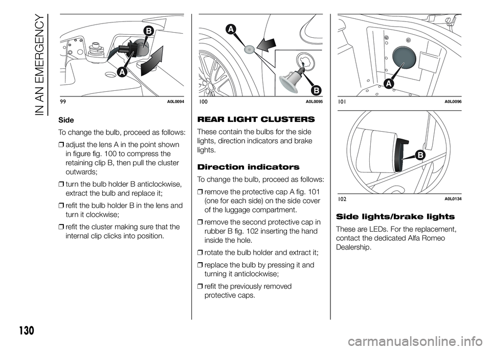
To change the bulb, proceed as follows:
ŌØÆadjust the lens A in the point shown
in figure fig. 100 to compress the
retaining clip B, then pull the cluster
outwards;
ŌØÆturn the bulb holder B anticlockwise,
extract the bulb and replace it;
ŌØÆrefit the bulb holder B in the lens and
turn it clockwise;
ŌØÆrefit the cluster making sure that the
internal clip clicks into position.REAR LIGHT CLUSTERS
These contain the bulbs for the side
lights, direction indicators and brake
lights.
Direction indicators
To change the bulb, proceed as follows:
ŌØÆremove the protective cap A fig. 101
(one for each side) on the side cover
of the luggage compartment.
ŌØÆremove the second protective cap in
rubber B fig. 102 inserting the hand
inside the hole.
ŌØÆrotate the bulb holder and extract it;
ŌØÆreplace the bulb by pressing it and
turning it anticlockwise;
ŌØÆrefit the previously removed
protective caps.Side lights/brake lights
These are LEDs. For the replacement,
contact the dedicated Alfa Romeo
Dealership.
99A0L0094100A0L0095101A0L0096
102A0L0134
130
IN AN EMERGENCY
Page 135 of 199

REAR FOG LIGHT/
REVERSING LIGHT
109)
To replace the rear fog light bulbs A fig.
103 or the reversing lights B fig. 103
proceed as follows:
ŌØÆturn the bulb holder C fig. 104
anticlockwise, extract the bulb and
replace it.3
rdBRAKE LIGHTS
These are LEDs. For the replacement,
contact the dedicated Alfa Romeo
Dealership.
NUMBER PLATE LIGHTS
To replace the bulbs proceed as
follows:
ŌØÆadjust the lens A in the point shown
in figure fig. 105 laterally to compress
the retaining clip, then pull the
number plate light cluster A out;
ŌØÆturn bulb holder B fig. 106
anticlockwise, extract bulb C and
replace it.
WARNING
109) The rear fog light and the
reversing light are located close to
the exhaust pipes; take the
utmost care not to get burnt
during the bulb replacement.
103A0L0097
104A0L0126
105A0L0136
106A0L0099
131
Page 136 of 199

INTERIOR BULB
REPLACEMENT
ROOF LIGHT
To change the bulb, proceed as follows:
ŌØÆremove roof light A fig. 107 working
at the points indicated by the arrows;ŌØÆopen protective flap B fig. 108 and
replace bulb C, releasing it from the
side contacts. Make sure that the
new bulb is correctly secured
between the contacts;
ŌØÆreclose protective flap B fig. 108 and
fix roof light A fig. 107 in its housing,
making sure that it is locked.
LUGGAGE
COMPARTMENT ROOF
LIGHT
To replace the bulb, proceed as follows:
ŌØÆopen the luggage compartment and
extract roof light A fig. 109, working
in the point shown by the arrow;
ŌØÆopen protection B and replace the
press-fitted bulb;
ŌØÆreclose protection B on the lens;ŌØÆrefit roof light A by inserting it in its
correct position, firstly on one side
and then pressing on the other side
until it clicks into place.
107A0L0100
108A0L0101
109A0L0140
132
IN AN EMERGENCY
Page 137 of 199
REPLACING FUSES
GENERAL INFORMATION
Fuses protect the electrical system:
they intervene (blow) in the event of a
fault or improper action on the system.
When a device does not work, check
the condition of its fuse: the filament
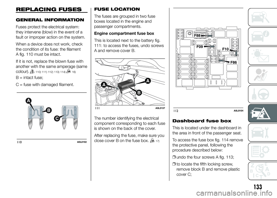
A fig. 110 must be intact.
If it is not, replace the blown fuse with
another with the same amperage (same
colour).
110) 111) 112) 113) 114)16)
B = intact fuse;
C = fuse with damaged filament.FUSE LOCATION
The fuses are grouped in two fuse
boxes located in the engine and
passenger compartments.
Engine compartment fuse box
This is located next to the battery fig.
111: to access the fuses, undo screws
A and remove cover B.
The number identifying the electrical
component corresponding to each fuse
is shown on the back of the cover.
After replacing the fuse, make sure you
close cover B on the fuse box.
17)
Dashboard fuse box
This is located under the dashboard in
the area in front of the passenger seat.
To access the fuse box fig. 114 remove
the protective panel, following the
procedure described below:
ŌØÆundo the four screws A fig. 113;
ŌØÆto locate the fifth locking screw,
remove block B and remove plastic
cover C;
110A0L0102
111A0L0137112A0L0104
133
Page 139 of 199

ENGINE COMPARTMENT FUSE BOX
fig. 112
DEVICE PROTECTED FUSE AMPERE
Headlight beam switch (for versions/markets, where provided) F09 5
Single tone hornF10 10
12 V socket / cigar lighter F86 15
External mirror defrosters F88 7.5
.
DASHBOARD FUSE BOX
fig. 114
DEVICE PROTECTED FUSE AMPERE
Central lockingF38 15
Two-way windscreen washer pump F43 20
+30 Driver side electric windows F47 20
+30 Passenger side electric windows F48 20
135
Page 142 of 199

WARNING
115) Before towing, turn the ignition
key to MAR-ON and then to STOP
without removing it. The steering
column will automatically lock
when the key is removed and the
wheels cannot be steered. Also
check that the gearbox/
transmission is in neutral (N).
116) When towing, remember that
the assistance of the brake servo
is absent. Consequently, more
force is required at the pedal
in order to brake. Do not
use flexible cables when towing
and avoid jerky movements. Make
sure not to damage parts in
contact with the car while towing.
When towing the car, you must
comply with all specific traffic
regulations, both in terms of the
towing device and behaviour
on the road. Do not start the
engine while towing the car.
Before tightening the ring, clean
the threaded housing thoroughly.
Make sure that the ring is fully
screwed into the housing before
towing the car.117) The tow hook must be used
exclusively for roadside
assistance operations. You are
allowed to tow the vehicle for
short distances using an
appropriate device in accordance
with the highway code (a rigid
bar), to move the vehicle on the
road in readiness for towing or
transport via a breakdown vehicle.
Tow hooks MUST NOT be used
to tow vehicles off the road or
where there are obstacles and/or
for towing operations using cables
or other non-rigid devices. In
compliance with the above
conditions, towing must take
place with the two vehicles (one
towing, the other towed) aligned
as much as possible along the
same centre line.
138
IN AN EMERGENCY
Page 145 of 199
SCHEDULED SERVICING PLAN
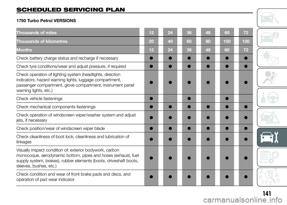
1750 Turbo Petrol VERSIONS
Thousands of miles 12 24 36 48 60 72
Thousands of kilometres 20 40 60 80 100 120
Months 12 24 36 48 60 72
Check battery charge status and recharge if necessaryŌŚÅŌŚÅŌŚÅŌŚÅŌŚÅŌŚÅ
Check tyre conditions/wear and adjust pressure, if requiredŌŚÅŌŚÅŌŚÅŌŚÅŌŚÅŌŚÅ
Check operation of lighting system (headlights, direction
indicators, hazard warning lights, luggage compartment,
passenger compartment, glove compartment, instrument panel
warning lights, etc.)ŌŚÅŌŚÅŌŚÅŌŚÅŌŚÅŌŚÅ
Check vehicle fasteningsŌŚÅŌŚÅŌŚÅ
Check mechanical components fasteningsŌŚÅŌŚÅŌŚÅŌŚÅŌŚÅŌŚÅ
Check operation of windscreen wiper/washer system and adjust
jets, if necessaryŌŚÅŌŚÅŌŚÅŌŚÅŌŚÅŌŚÅ
Check position/wear of windscreen wiper bladeŌŚÅŌŚÅŌŚÅŌŚÅŌŚÅŌŚÅ
Check cleanliness of boot lock, cleanliness and lubrication of
linkagesŌŚÅŌŚÅŌŚÅŌŚÅŌŚÅŌŚÅ
Visually inspect condition of: exterior bodywork, carbon
monocoque, aerodynamic bottom, pipes and hoses (exhaust, fuel
supply system, brakes), rubber elements (boots, driveshaft boots,
sleeves, bushes, etc.)ŌŚÅŌŚÅŌŚÅŌŚÅŌŚÅŌŚÅ
Check condition and wear of front brake pads and discs, and
operation of pad wear indicatorŌŚÅŌŚÅŌŚÅŌŚÅŌŚÅŌŚÅ
141
Page 148 of 199
PERIODIC CHECKS
Every 1,000 km or before long
journeys, check and, if necessary, top
up the following:
ŌØÆengine coolant level;
ŌØÆbrake fluid;
ŌØÆscreen washer fluid;
ŌØÆtyre inflation pressure and condition;
ŌØÆoperation of lighting system
(headlamps, direction indicators,
hazard warning lights, etc.);
ŌØÆoperation of screen washing/wiping
system and positioning/wear of
wiper blade.
Every 3,000 km, check and top up if
required: engine oil level.
HEAVY-DUTY USE OF
THE CAR
If the car is used mainly under one of
the following conditions:
ŌØÆif the car is used under demanding
conditions, e.g. on track;
ŌØÆdusty roads;
ŌØÆshort, repeated journeys (less than
7ŌĆō8 km) at sub-zero outside
temperatures;
ŌØÆengine often idling or driving long
distances at low speeds or long
periods of inactivity;
the following checks must be carried
out more often than indicated in the
Scheduled Servicing Plan:
ŌØÆcheck of front and rear disc brake
pad condition and wear;
ŌØÆcheck cleanliness of tailgate locks,
cleanliness and lubrication of linkage;
ŌØÆvisually inspect conditions of: engine,
gearbox, transmission, pipes and
hoses (exhaust - fuel system -
brakes) and rubber elements (boots -
sleeves - bushes - etc.);
ŌØÆcheck battery charge and battery
fluid level (electrolyte);
ŌØÆvisually inspect condition of the
accessory drive belts;ŌØÆcheck and, if necessary, change
engine oil and replace oil filter;
ŌØÆcheck and, if necessary, replace air
cleaner.
Using the car on track should be
regarded as an exception. The car has
been designed and produced for road
use.
144
SERVICING AND MAINTENANCE
Page 151 of 199
ENGINE OIL
Check that the oil level is between the
MIN and MAX marks on the dipstick
A fig. 119.
For this check, take out the dipstick
from its seat, clean it with a lint-free
cloth, reinsert the dipstick; take it out
again and check the oil level.
121)
If the oil level is near or under the MIN
mark, add oil through the filler B fig.
119 until it reaches the MAX mark.
22)
Take out the engine oil dipstick A, clean
it with a lint-free cloth and reinsert it.
Extract the engine oil dipstick again and
check that the level is between the
MIN and MAX marks on the dipstick.
121)
Make sure to tighten the oil plug in
its seat thoroughly after possibly
topping the oil up.
The range between the MIN and MAX
levels corresponds to approximately
1 litre of oil.
Engine oil consumption
23)3)
The maximum engine oil consumption
is usually 400 grams every 1,000 km.When the car is new, the engine needs
to run in, therefore the engine oil
consumption can only be considered
stabilised after the first 5,000 - 6,000
km.
IMPORTANT After adding or changing
the oil, let the engine run for a few
seconds and wait a few minutes after
stopping it before you check the level.
ENGINE COOLANT
24)122)
The coolant level must be checked
when the engine is cold and must
range between the MIN and MAX
marks on the reservoir.
If the level is too low, unscrew reservoir
plug C fig. 119 and add the fluid
described in the "Fluids and lubricants"
paragraph of the "Technical
Specifications" chapter.
WINDSCREEN WASHER
FLUID
123) 124)
To check the windscreen washer fluid
level, proceed as follows:
ŌØÆto avoid any interference during the
procedure, lift the windscreen wiper
blade according to the "Windscreen
wiper" paragraph in the
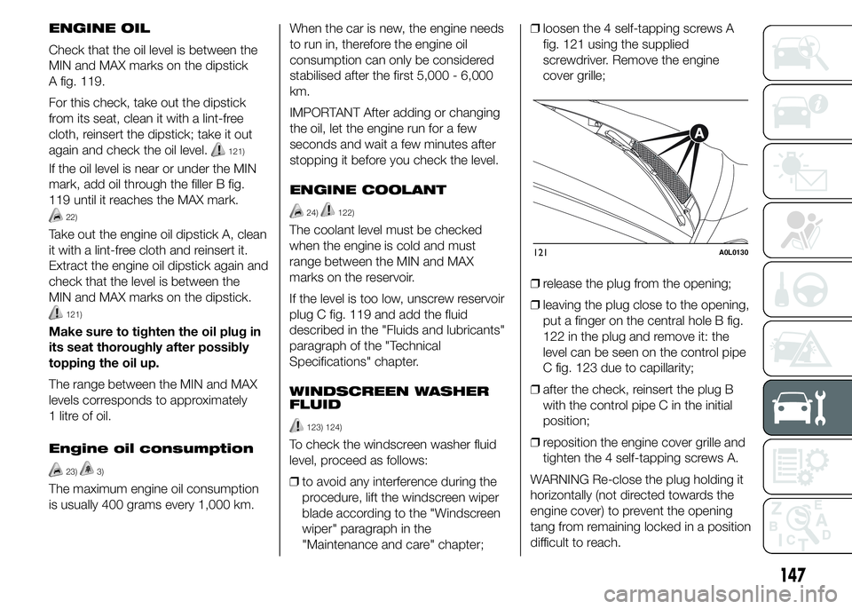
"Maintenance and care" chapter;ŌØÆloosen the 4 self-tapping screws A
fig. 121 using the supplied
screwdriver. Remove the engine
cover grille;
ŌØÆrelease the plug from the opening;
ŌØÆleaving the plug close to the opening,
put a finger on the central hole B fig.
122 in the plug and remove it: the
level can be seen on the control pipe
C fig. 123 due to capillarity;
ŌØÆafter the check, reinsert the plug B
with the control pipe C in the initial
position;
ŌØÆreposition the engine cover grille and
tighten the 4 self-tapping screws A.
WARNING Re-close the plug holding it
horizontally (not directed towards the
engine cover) to prevent the opening
tang from remaining locked in a position
difficult to reach.
121A0L0130
147
Page 159 of 199
Replacing the
windscreen wiper blade
Proceed as follows:
ŌØÆlift the windscreen wiper blade,
following the instructions given
preciously;
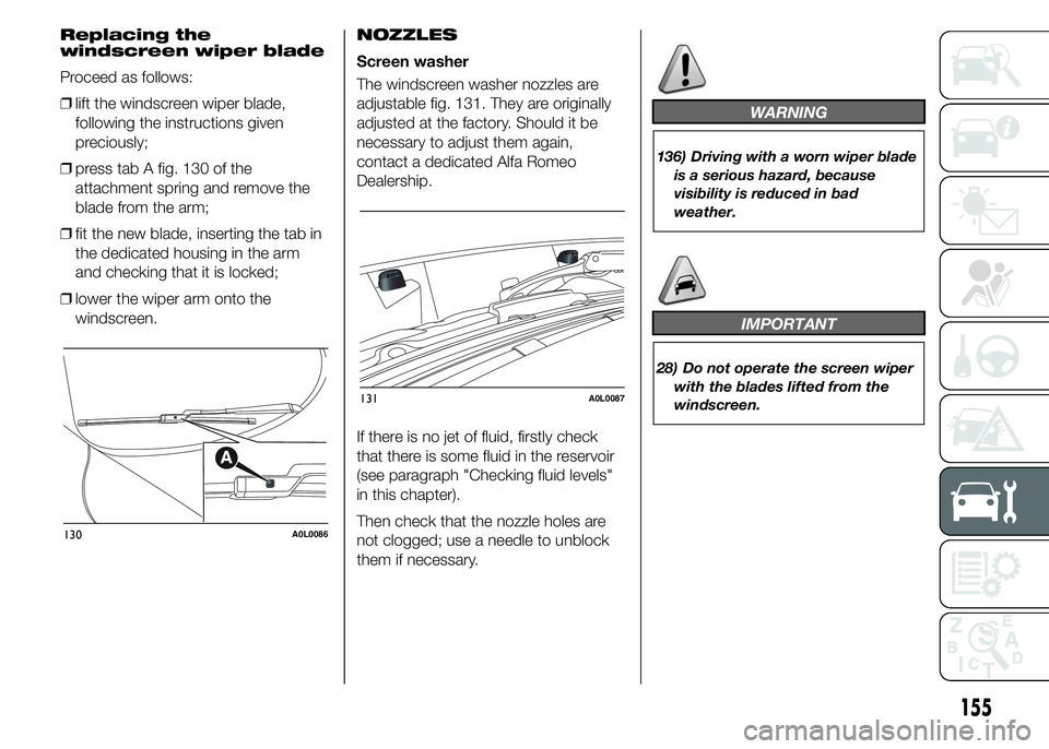
ŌØÆpress tab A fig. 130 of the
attachment spring and remove the
blade from the arm;
ŌØÆfit the new blade, inserting the tab in
the dedicated housing in the arm
and checking that it is locked;
ŌØÆlower the wiper arm onto the
windscreen.NOZZLES
Screen washer
The windscreen washer nozzles are
adjustable fig. 131. They are originally
adjusted at the factory. Should it be
necessary to adjust them again,
contact a dedicated Alfa Romeo
Dealership.
If there is no jet of fluid, firstly check
that there is some fluid in the reservoir
(see paragraph "Checking fluid levels"
in this chapter).
Then check that the nozzle holes are
not clogged; use a needle to unblock
them if necessary.
WARNING
136) Driving with a worn wiper blade
is a serious hazard, because
visibility is reduced in bad
weather.
IMPORTANT
28) Do not operate the screen wiper
with the blades lifted from the
windscreen.
130A0L0086
131A0L0087
155