dashboard Alfa Romeo 4C 2016 Owner handbook (in English)
[x] Cancel search | Manufacturer: ALFA ROMEO, Model Year: 2016, Model line: 4C, Model: Alfa Romeo 4C 2016Pages: 182, PDF Size: 9.49 MB
Page 96 of 182
WARNING
72)Do not apply stickers or other objects
to the steering wheel or the passenger side
airbag cover. Do not place objects on the
passenger side of the dashboard because
these could interfere with the correct
opening of the passenger airbag and
cause injury to occupants.
73)Always drive keeping your hands on
the steering wheel rim so the airbag can
inflate freely if necessary. Do not drive with
your body bent forward. Keep your back
straight against the backrest.
74)Instructions for deactivating the front
passenger airbag can be found in the
"Menu Options" paragraph of the
"Knowing the instrument panel" chapter.
Please note that under these conditions
the airbag will NOT deploy when required
(accident).
75)Do not rest your head, arms or elbows
on the door to prevent injury during airbag
deployment.
76)Never lean your head, arms or elbows
out of the window.
77)If the
warning light does not switch
on when the key is turned to MAR, or stays
on while driving (on some versions together
with a message on the display) there may
be a fault in the restraint systems. In this
case, airbags or pretensioners may not be
activated in the case of an accident or (in a
lesser number of cases) they may be
activated incorrectly. Before proceeding,
contact a dedicated Alfa Romeo Dealership
to have the system checked immediately.78)Do not travel carrying objects on your
lap, in front of your chest or between your
lips (pipe, pencils, etc.): they could cause
severe injury if the airbag is deployed.
79)If the car has been subject to theft,
attempted theft, vandalism, or flooding,
have the airbag system inspected at a
dedicated Alfa Romeo Dealership.
80)The airbags may also be deployed
when the car is not moving, if the key is
inserted and turned to MAR even when the
engine is off, if the car is hit by another
moving vehicle. Also remember that no
safety device (airbags or pretensioners) will
activate in the event of impact when the
key is at STOP. Non-deployment of these
devices under these circumstances does
not therefore indicate a system
malfunction.
81)When the ignition key is turned to
MAR, the
warning light comes on
constantly for the first 4 seconds. Then, if
the warning light remains on, this means
the passenger's protection has been
deactivated; if the warning light switches
off, instead, the passenger's protection is
enabled.
82)The front airbag is designed to be
deployed for impacts of a greater intensity
than for the pretensioners. For impacts
whose intensity falls between the two
levels, normally, only the pretensioners will
be activated.
83)The airbag does not replace seat belts
but increases their efficiency. Because front
airbags are not deployed for low-speed
frontal impacts, side collisions, rear shunts
or rollovers, occupants are protected only
by their seat belts, which must always be
fastened.
93
Page 109 of 182
REPAIRING A WHEEL
GENERAL
INSTRUCTIONS
The car is equipped with a quick tyre
repair device called the "Fix&Go
automatic" kit.
92) 94)
To use it, follow the instructions below.93) 95) 96)13)2)
"Fix&Go automatic" KIT
It is located in the luggage
compartment.
The kit includes:
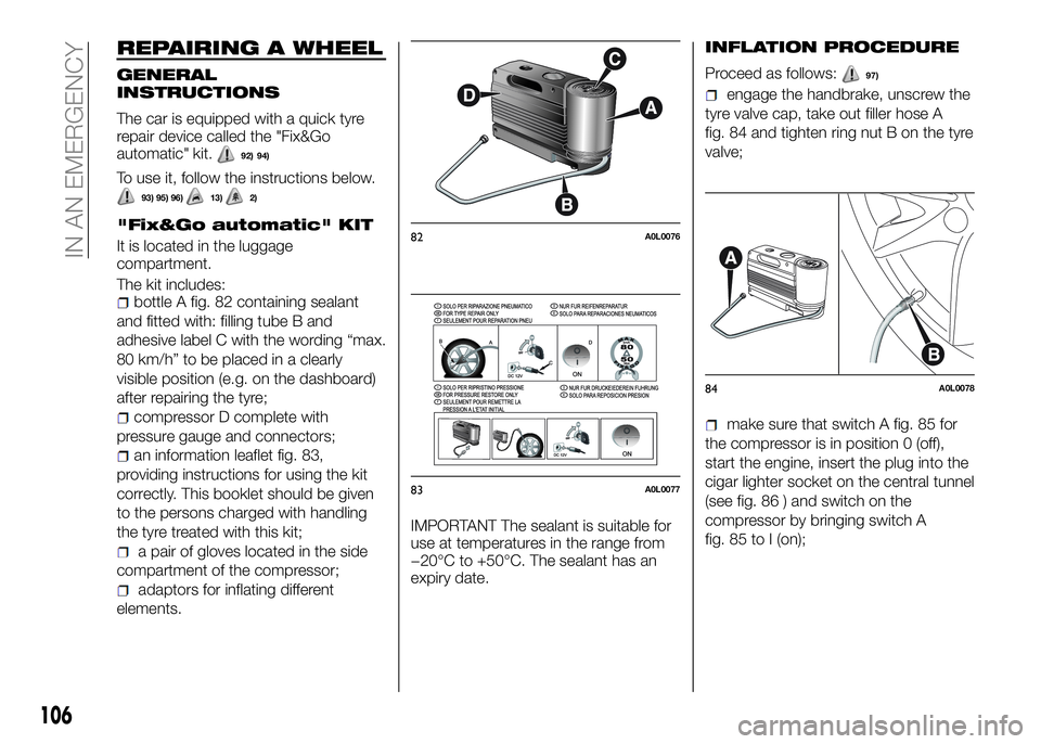
bottle A fig. 82 containing sealant
and fitted with: filling tube B and
adhesive label C with the wording “max.
80 km/h” to be placed in a clearly
visible position (e.g. on the dashboard)
after repairing the tyre;
compressor D complete with
pressure gauge and connectors;
an information leaflet fig. 83,
providing instructions for using the kit
correctly. This booklet should be given
to the persons charged with handling
the tyre treated with this kit;
a pair of gloves located in the side
compartment of the compressor;
adaptors for inflating different
elements.IMPORTANT The sealant is suitable for
use at temperatures in the range from
−20°C to +50°C. The sealant has an
expiry date.
INFLATION PROCEDURE
Proceed as follows:97)
engage the handbrake, unscrew the
tyre valve cap, take out filler hose A
fig. 84 and tighten ring nut B on the tyre
valve;
make sure that switch A fig. 85 for
the compressor is in position 0 (off),
start the engine, insert the plug into the
cigar lighter socket on the central tunnel
(see fig. 86 ) and switch on the
compressor by bringing switch A
fig. 85 to I (on);
82A0L0076
83A0L0077
84A0L0078
106
IN AN EMERGENCY
Page 123 of 182
REPLACING FUSES
GENERAL INFORMATION
Fuses protect the electrical system:
they intervene (blow) in the event of a
fault or improper action on the system.
When a device does not work, check
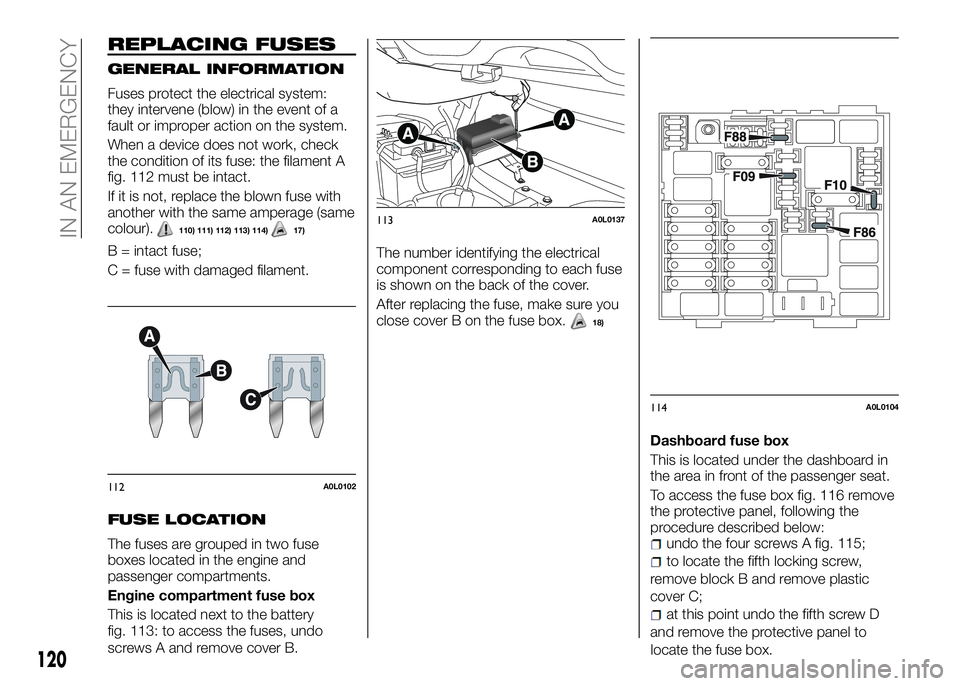
the condition of its fuse: the filament A
fig. 112 must be intact.
If it is not, replace the blown fuse with
another with the same amperage (same
colour).
110) 111) 112) 113) 114)17)
B = intact fuse;
C = fuse with damaged filament.
FUSE LOCATION
The fuses are grouped in two fuse
boxes located in the engine and
passenger compartments.
Engine compartment fuse box
This is located next to the battery
fig. 113: to access the fuses, undo
screws A and remove cover B.The number identifying the electrical
component corresponding to each fuse
is shown on the back of the cover.
After replacing the fuse, make sure you
close cover B on the fuse box.
18)
Dashboard fuse box
This is located under the dashboard in
the area in front of the passenger seat.
To access the fuse box fig. 116 remove
the protective panel, following the
procedure described below:
undo the four screws A fig. 115;
to locate the fifth locking screw,
remove block B and remove plastic
cover C;
at this point undo the fifth screw D
and remove the protective panel to
112A0L0102
113A0L0137
114A0L0104
120
IN AN EMERGENCY
locate the fuse box.
Page 125 of 182
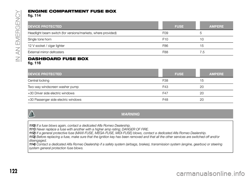
ENGINE COMPARTMENT FUSE BOXfig. 114
DEVICE PROTECTEDFUSE AMPERE
Headlight beam switch (for versions/markets, where provided) F09 5
Single tone hornF10 10
12 V socket / cigar lighter F86 15
External mirror defrosters F88 7.5
DASHBOARD FUSE BOXfig. 116
DEVICE PROTECTEDFUSE AMPERE
Central lockingF38 15
Two-way windscreen washer pump F43 20
+30 Driver side electric windows F47 20
+30 Passenger side electric windows F48 20
WARNING
110)If a fuse blows again, contact a dedicated Alfa Romeo Dealership.
111)Never replace a fuse with another with a higher amp rating; DANGER OF FIRE.
112)If a general protective fuse (MAXI-FUSE, MEGA-FUSE, MIDI-FUSE) blows, contact a dedicated Alfa Romeo Dealership.
113)Before replacing a fuse, make sure that the ignition key has been removed and that all the other services are switched off and/or
disengaged.
114)Contact a dedicated Alfa Romeo Dealership if a safety system (airbags, brakes), transmission system (engine, gearbox) or steering
system general protection fuse blows.
122
IN AN EMERGENCY
Page 149 of 182
IDENTIFICATION
DATA
The identification data of the car are:VIN plate;
Chassis marking;
Bodywork paint identification plate;
Engine marking.
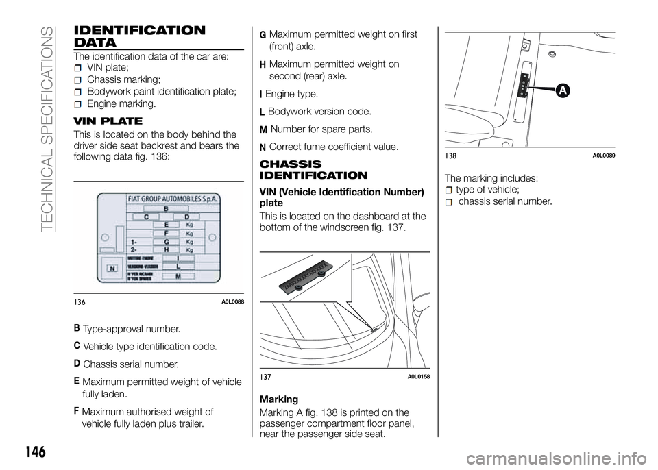
VIN PLATE
This is located on the body behind the
driver side seat backrest and bears the
following data fig. 136:
BType-approval number.
CVehicle type identification code.
DChassis serial number.
EMaximum permitted weight of vehicle
fully laden.
FMaximum authorised weight of
vehicle fully laden plus trailer.
GMaximum permitted weight on first
(front) axle.
HMaximum permitted weight on
second (rear) axle.
IEngine type.
LBodywork version code.
MNumber for spare parts.
NCorrect fume coefficient value.
CHASSIS
IDENTIFICATION
VIN (Vehicle Identification Number)
plate
This is located on the dashboard at the
bottom of the windscreen fig. 137.
Marking
Marking A fig. 138 is printed on the
passenger compartment floor panel,
near the passenger side seat.The marking includes:type of vehicle;
chassis serial number.
136A0L0088
137A0L0158
138A0L0089
146
TECHNICAL SPECIFICATIONS