engine Alfa Romeo 4C 2016 Owner handbook (in English)
[x] Cancel search | Manufacturer: ALFA ROMEO, Model Year: 2016, Model line: 4C, Model: Alfa Romeo 4C 2016Pages: 182, PDF Size: 9.49 MB
Page 32 of 182
headlights deactivate, the dipped beam
headlights reactivate and the warning
light
switches off.
FLASHING
To do this, pull the stalk towards the
steering wheel (unstable position)
regardless of the position of ring nut A.
The
warning light switches on in
the instrument panel.
REAR FOG LIGHTS
For the activation and deactivation of
the rear fog lights, refer to the
"Controls" section.
DIRECTION INDICATORS
Bring the stalk to the (stable) position:upwards: activates right direction
indicator;
downwards: activates left direction
indicator.
Warning light
orwill blink on the
instrument panel.
The direction indicators are switched off
automatically when the steering wheel
is straightened.
"Lane change" function
If you wish to signal a lane change,
place the left stalk in the unstable
position for less than half a second. The
direction indicator on the side selected
will flash five times and then switch off
automatically.
"FOLLOW ME HOME"
DEVICE
This device allows you to illuminate the
area in front of the car for a certain
amount of time.
Activation
With the key turned to STOP or
removed, pull stalk A towards the
steering wheel within 2 minutes from
when the engine is turned off.
Each time the stalk is moved, the lights
stay on for an extra 30 seconds up to a
maximum of 210 seconds; then the
lights are switched off automatically.
Also, each time the stalk is operated,
the
warning light on the
instrument panel switches on. The
display shows the time set for the
function and the corresponding
graphics.
The warning light comes on when the
lever is operated and stays on until the
function is automatically deactivated.
Each movement of the stalk only
increases the amount of time the lights
stay on.
Deactivation
Keep the stalk pulled towards the
steering wheel for more than 2
seconds.
WINDOW CLEANING
The right stalk controls screen
wiper/washer operation.
This operates only with the ignition key
at MAR-ON.
SCREEN WIPER/WASHER
Operation12) 13)
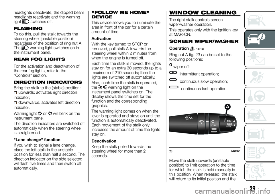
Ring nut A fig. 23 can be set to the
following positions:
Owiper off;
intermittent operation;
continuous slow operation;
continuous fast operation.
Move the stalk upwards (unstable
position) to limit operation to the time
for which the stalk is held manually in
this position. When released, the stalk
will return to its initial position and the
23A0L0021
29
Page 34 of 182
Increasing speed
This can be done in two ways:by pressing the accelerator and
storing the new speed reached
or
by moving the stalk upwards (+) until
the new speed, which will be stored
automatically, is reached.
Each movement of the stalk
corresponds to an increase in speed of
about 1 km/h, while keeping the stalk
held upwards will continuously increase
the speed.
Decreasing speed
This can be done in two ways:by deactivating the device and then
storing the new speed
or
by moving the stalk downwards (–)
until the new speed, which will be
stored automatically, is reached.
Each movement of the stalk will
correspond to a slight reduction in
speed of about 1 km/h, while keeping
the stalk held downwards will decrease
the speed continuously.
Deactivation
The device can be switched off by the
driver in the following ways:
by turning ring nut A fig. 24 toO;
by switching off the engine;
by pressing the CANCEL/RESUME
button;
by pressing the brake pedal or the
accelerator; in this last case the system
is not completely deactivated but gives
priority to the acceleration request. The
device still remains active, without the
need to press the CANCEL/RESUME
button to return to the previous
condition once acceleration is
concluded.
WARNING
14)When driving with device active, do not
press the "N" button on the transmission
control panel.
15)If operation of the device is faulty or in
the case of failure, turn ring nut A fig. 24 to
O and contact a dedicated Alfa Romeo
Dealership.
ROOF LIGHT
Operation
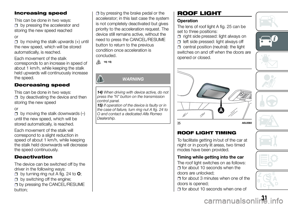
The lens of roof light A fig. 25 can be
set to three positions:
right side pressed: light always on
left side pressed: light always off
central position (neutral): the light
switches on and off when the doors are
opened or closed.
ROOF LIGHT TIMING
To facilitate getting in/out of the car at
night or in poorly lit areas, two timed
modes have been provided.
Timing while getting into the car
The roof light switches on as follows:
for about 10 seconds when the
doors are unlocked;
for about 3 minutes when one of the
doors is opened;
for about 10 seconds when one of
25A0L0060
31
14) 15)
Page 35 of 182
the doors is closed.
The timed period is interrupted when
the ignition key is turned to MAR-ON.
Timing while getting out of the car
After removing the key from the ignition
switch, the roof light will switch on as
follows:
for about 10 seconds, if the key is
removed within 2 minutes of the engine
switching off;
for about 3 minutes when one of the
doors is opened;
for about 10 seconds when one of
the doors is closed.
The timing stops automatically when
the doors are locked.
CONTROLS
HAZARD WARNING
LIGHTS
Operation
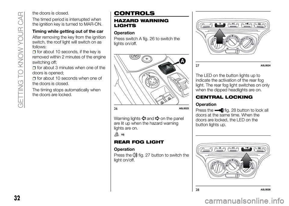
Press switch A fig. 26 to switch the
lights on/off.
Warning lights
andon the panel
are lit up when the hazard warning
lights are on.
16)
REAR FOG LIGHT
Operation
Press the
fig. 27 button to switch the
light on/off.The LED on the button lights up to
indicate the activation of the rear fog
light. The rear fog light switches on only
when the dipped headlights are on.
CENTRAL LOCKING
Operation
Press the
fig. 28 button to lock all
doors at the same time. When the
doors are locked, the LED on the
button lights up.26A0L0023
27A0L0024
28A0L0026
32
GETTING TO KNOW YOUR CAR
Page 36 of 182
Locking takes place irrespective of the
position of the ignition key.
FUEL CUT-OFF SYSTEM
Operation
This intervenes in the event of impact,
causing:
fuel supply cut-off with the engine
consequently switching off;
the automatic unlocking of the doors;
the switching on of the interior lights;
the switching on of the hazard
warning lights.
The digital
warning light and the
dedicated message on the display
indicate the intervention of the system.
Carefully check the car for fuel leaks, for
instance in the engine compartment,
under the car or near the tank area.
17)
After a collision, turn the ignition key to
STOP to prevent the battery from
running down.
To restore the correct operation of the
car, proceed as follows:
bring the left exterior light control
stalk to central position (neutral);
turn the ignition key to the MAR-ON
position;
activate the right direction indicator;
deactivate the right direction
indicator;
activate the left direction indicator;
deactivate the left direction indicator;
activate the right direction indicator;
deactivate the right direction
indicator;
activate the left direction indicator;
deactivate the left direction indicator;
turn the ignition key to the STOP
position;
turn the ignition key to the MAR-ON
position.
WARNING
16)The use of hazard warning lights is
governed by the Highway Code of the
country you are driving in: comply with
legal requirements.
17)If, after an impact, you smell fuel or
notice leaks from the fuel system, do not
reactivate the system to avoid the risk of
fire.
INTERIOR FITTINGS
STORAGE
COMPARTMENTS
Front
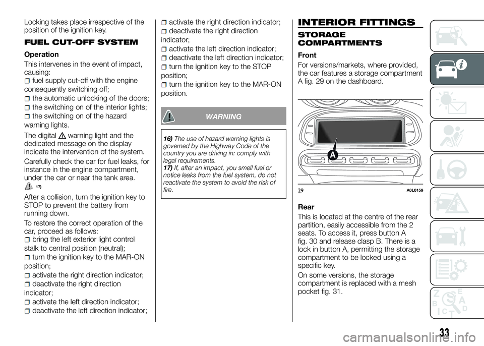
For versions/markets, where provided,
the car features a storage compartment
A fig. 29 on the dashboard.
Rear
This is located at the centre of the rear
partition, easily accessible from the 2
seats. To access it, press button A
fig. 30 and release clasp B. There is a
lock in button A, permitting the storage
compartment to be locked using a
specific key.
On some versions, the storage
compartment is replaced with a mesh
pocket fig. 31.
29A0L0159
33
Page 41 of 182
of travel position has been reached;
proceed in the same way as
described in points 1 and 2 for the
passenger side door;
make sure that the initialisation is
correct by checking that the windows
work automatically.
WARNING
20)Incorrect use of the electric windows
may be dangerous. Before and during their
operation, ensure that any passengers are
not at risk from the moving glass either by
personal objects getting caught in the
mechanism or by being hit by it directly.
When leaving the car, always remove the
key from the ignition to prevent accidental
operation of the electric windows from
being a hazard for those still on board.
LUGGAGE
COMPARTMENT /
ENGINE COVER
21)
OPENING
IMPORTANT During normal car
operation, the luggage compartment
can reach temperatures above 65°C.
Pay attention when transporting objects
that may be damaged at such
temperatures. Do not keep aerosol
cans in the car: danger of explosion.
Aerosol cans must not be exposed to
temperatures above 50°C.
Procedure
22) 23)
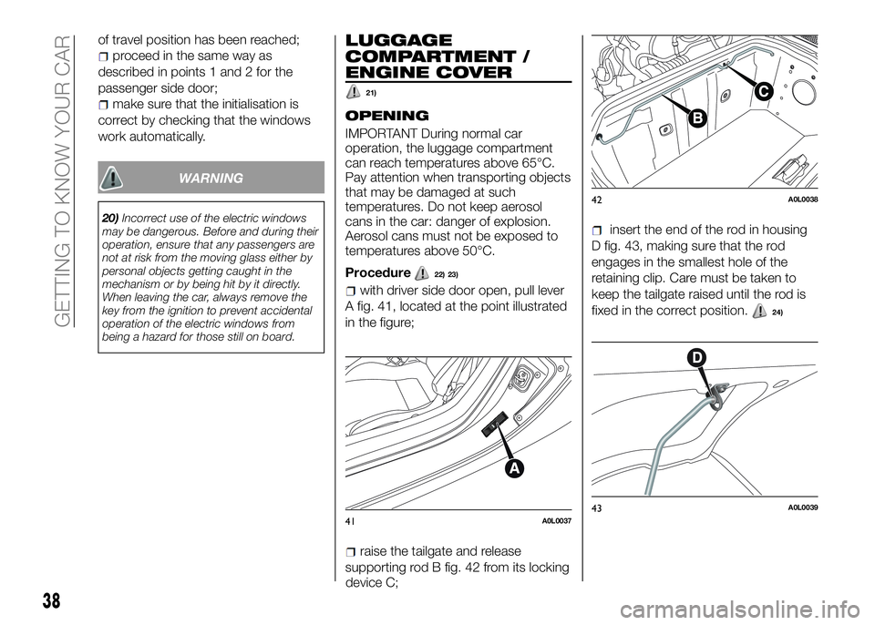
with driver side door open, pull lever
A fig. 41, located at the point illustrated
in the figure;
raise the tailgate and release
supporting rod B fig. 42 from its locking
device C;
insert the end of the rod in housing
D fig. 43, making sure that the rod
engages in the smallest hole of the
retaining clip. Care must be taken to
keep the tailgate raised until the rod is
fixed in the correct position.
24)
41A0L0037
42A0L0038
43A0L0039
38
GETTING TO KNOW YOUR CAR
Page 42 of 182
the tailgate when raising, in order to
prevent any external occurrence (e.g. a
gust of wind) from suddenly opening
the tailgate to end of travel. Additionally,
in order to prevent any damage to the
car or broken windows, do not force
the tailgate beyond the opening
position necessary to secure the
supporting rod B in the hole of the
retaining clip.
CLOSING
Procedure25)
hold the tailgate up with one hand
and use the other to remove rod B
fig. 42 from housing D fig. 43 and
reinsert it in its locking device C fig. 42;
lower the engine cover to
approximately 20 centimetres from the
engine compartment and let it drop.
Make sure that the engine cover is
completely closed and not only
fastened in safety position by trying to
open it. If it is not completely closed, do
not press the engine cover down, but
raise it and repeat the procedure.
IMPORTANT Always check that the
tailgate is closed correctly to prevent it
from opening while the car is travelling.
WARNING
21)The maximum permitted load in the
luggage compartment, in addition to the
kits provided, is 15 kg.
22)When accessing the rear luggage
compartment, take care with parts that
may be hot, owing to the adjacent engine
compartment. Danger of serious burns.
23)Perform these operations only when
the car is stationary.
24)The tailgate may drop suddenly if the
supporting rod is not positioned correctly.
25)For safety reasons, the tailgate must
always be closed properly while the car is
travelling. Therefore, always make sure that
the tailgate is closed properly and that the
lock is engaged. If you realise during travel
that the lock is not fully engaged, stop
immediately and close the tailgate in the
correct manner.
HEADLIGHTS
LIGHT BEAM DIRECTION
The correct orientation of the headlights
is important for the driver's comfort and
safety as well as for all other road users.
This is also covered by a specific rule of
the highway code.
The headlights must be correctly
directed to ensure the best visibility
conditions for all drivers. Contact a
dedicated Alfa Romeo Dealership to
have the headlights checked and
adjusted.
ADJUSTING THE
HEADLIGHTS ABROAD
The dipped beam headlights are
aligned to comply with the regulations
of the country of purchase. When in
countries where you drive on the other
side of the road, you need to alter the
beam direction in order not to dazzle
the vehicles travelling in the opposite
direction, proceeding as follows:
39
IMPORTANT Maintain a tight grip on
Page 43 of 182
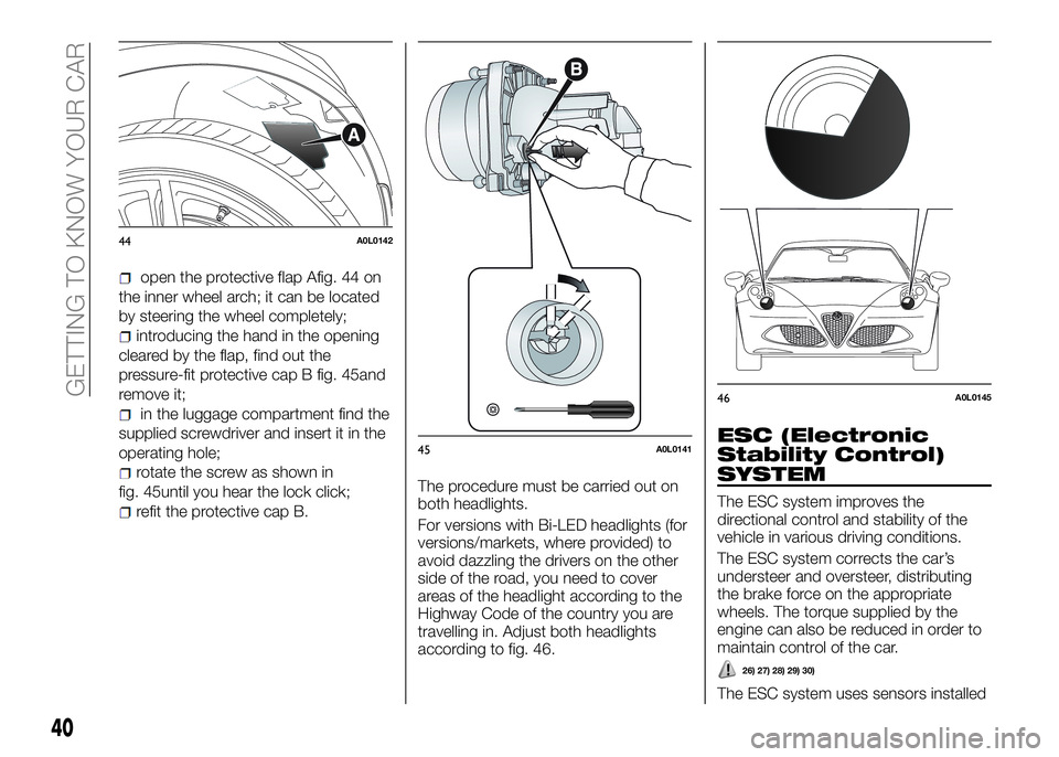
open the protective flap Afig. 44 on
the inner wheel arch; it can be located
by steering the wheel completely;
introducing the hand in the opening
cleared by the flap, find out the
pressure-fit protective cap B fig. 45and
remove it;
in the luggage compartment find the
supplied screwdriver and insert it in the
operating hole;
rotate the screw as shown in
fig. 45until you hear the lock click;
refit the protective cap B.The procedure must be carried out on
both headlights.
For versions with Bi-LED headlights (for
versions/markets, where provided) to
avoid dazzling the drivers on the other
side of the road, you need to cover
areas of the headlight according to the
Highway Code of the country you are
travelling in. Adjust both headlights
according to fig. 46.
ESC (Electronic
Stability Control)
SYSTEM
The ESC system improves the
directional control and stability of the
vehicle in various driving conditions.
The ESC system corrects the car’s
understeer and oversteer, distributing
the brake force on the appropriate
wheels. The torque supplied by the
engine can also be reduced in order to
maintain control of the car.
26) 27) 28) 29) 30)
The ESC system uses sensors installed
44A0L0142
45A0L0141
46A0L0145
40
GETTING TO KNOW YOUR CAR
Page 44 of 182
on the car to determine the trajectory
that the driver intends to follow and
compares it with the car’s effective
trajectory. When the real trajectory
deviates from the desired trajectory, the
ESC system intervenes to counter the
car’s understeer or oversteer.
Oversteer: occurs when the vehicle is
turning more than it should according
to the angle of the steering wheel.
Understeer: occurs when the vehicle
is turning less than it should according
to the angle of the steering wheel
The ESC system also includes the
following systems:
ABS
EBD
CBC
DTC
ASR
HILL HOLDER
HBA
“ELECTRONIC Q2” (“E-Q2”)
"PRE-FILL" (RAB - Ready Alert
Brake)
SYSTEM ACTIVATION
The ESC system activates automatically
when the engine is started and can only
be deactivated by selecting "Race"
mode. For more details, refer to the
"Alfa DNA system" paragraph in this
chapter.
SYSTEM INTERVENTION
This is indicated by the flashing of thewarning light on the instrument
panel, to inform the driver that the car is
in critical stability and grip conditions.
ABS
This system, which is an integral part of
the braking system, prevents one or
more wheels from locking and slipping
in all road surface conditions,
irrespective of the intensity of the
braking action, ensuring that the car
can be controlled even during
emergency braking and optimising
stopping distances.
The system intervenes when braking
and the wheels are about to lock,
typically in emergency braking or
low-grip conditions, when locking may
be more frequent.
The system also improves control and
stability of the car when braking on a
surface where the grip of the left and
right wheels varies, or on corners.
31) 32) 33) 34) 35) 36) 37)
System intervention
A slight pulsing of the brake pedal and
noise indicates the intervention of the
ABS: this is completely normal when
the system intervenes.
EBD SYSTEM
The EBD system is an integral part of
the ABS system and intervenes during
braking, distributing the brake force
optimally between front and rear
wheels.
This guarantees greater braking stability
for the vehicle, preventing sudden
locking of the rear wheels and the
consequent instability of the vehicle.
CBC (Cornering Brake
Control) SYSTEM
The system acts when braking on
corners, optimising the distribution of
brake pressure on the four wheels: the
system prevents the wheels on the
inside of the corner (less affected by the
weight of the car) from locking, ensuring
better stability and direction for the car.
DTC (Drag Torque
Control) SYSTEM
This is an integral part of the ABS
system and intervenes in the case of
sudden downshifting, or during braking
when the ABS intervenes, restoring
torque to the engine and thus
preventing excessive drag at the drive
wheels, which may lead the wheels to
lock and a loss of car stability, above all
in low-grip conditions.
41
Page 45 of 182
ASR (AntiSlip
Regulation) SYSTEM
29) 30) 38) 39) 40)
This is an integral part of the ESC
system and automatically operates in
the event of one or both drive wheels
slipping, loss of grip on wet roads
(aquaplaning) and acceleration on
slippery, snowy or icy roads, etc.
Depending on the slipping conditions,
two different control systems are
activated:
if the slipping involves both drive
wheels, the ASR system intervenes,
reducing the power transmitted by the
engine;
if the slipping only involves one of
the drive wheels, it also intervenes
automatically, braking the wheel that is
slipping.
System intervention
This is indicated by the flashing of the
warning light on the instrument
panel, to inform the driver that the car is
in critical stability and grip conditions.
HILL HOLDER SYSTEM
This is an integral part of the ESC
system and facilitates starting on
slopes, activating automatically in the
following cases:
uphill: car stationary on a road with a
gradient higher than 5%, engine
running, brake pressed and
transmission in neutral or gear otherthan reverse engaged;
downhill: car stationary on a road
with a gradient higher than 5%, engine
running, brake pressed and reverse
gear engaged.
When setting off, the ESC system
control unit maintains the braking
pressure on the wheels until the engine
torque necessary for starting is
reached, or in any case for a maximum
of 2 seconds, allowing your right foot to
be moved easily from the brake pedal
to the accelerator.
When the 2 seconds have elapsed,
without starting, the system is
automatically deactivated, gradually
releasing the braking pressure. During
this release stage, the typical brake
disengagement noise, indicating that
the car is going to move imminently,
can be heard.
IMPORTANT The Hill Holder system is
not a parking brake; therefore, never
leave the vehicle without having
engaged the handbrake, turned the
engine off and engaged first gear, so
that the vehicle is parked in safe
conditions (for further information read
the "Parking" paragraph in the "Starting
and driving" chapter).
IMPORTANT There may be situations
on small gradients (less than 8%), with
vehicle laden, in which the Hill Holder
system may not activate, causing a
slight reversing motion and increasingthe risk of collision with another vehicle
or object. The driver is, in any case,
responsible for safe driving.
HBA (Hydraulic Brake
Assistant) SYSTEM
41) 42) 43)
The HBA system is designed to
improve the car’s braking capacity
during emergency braking. The system
detects emergency braking by
monitoring the speed and force with
which the brake pedal is pressed, and
consequently applies the optimal brake
pressure. This can reduce the braking
distance, the HBA system therefore
completes the ABS.
Maximum assistance from the HBA
system is obtained pressing the brake
pedal very quickly. In addition, the brake
pedal should be pressed continuously
during braking, avoiding intermittent
presses, to get the most out of the
system.
Do not reduce pressure on the brake
pedal until braking is no longer
necessary.
The HBA system is deactivated when
the brake pedal is released.
“ELECTRONIC Q2”
SYSTEM (“E-Q2”)
The "Electronic Q2" system intervenes
during acceleration on corners, braking
the inner drive wheel and thus
increasing the traction of the outer
wheel (which bears more of the car’s
42
GETTING TO KNOW YOUR CAR
Page 47 of 182
“Alfa DNA” SYSTEM
(Dynamic car
control system)
This device allows, using lever A
fig. 47 (on the central tunnel), four car
response modes to be selected
according to driving style and road
conditions:
d=DynamicorRace(sports driving
mode);
n=Natural(mode for driving in
normal conditions);
a=All Weather(mode for driving in
poor grip conditions, such as rain and
snow).
The device also acts on the dynamic
car control systems (engine,
gearbox/transmission, ESC system).
DRIVING MODES
Lever A is monostable type. In other
words, it always remains in a central
position.
The selected driving mode is indicated
by the corresponding LED switching on
in the panel and by an indication on the
display.
“Natural” MODE
It is a manufacturer-recommended
mode aimed at comfort and safety in
normal grip and driving conditions.
ESC and ASR systems:intervention
thresholds aimed at providing comfort
and safety in normal grip and driving
conditions.
"Electronic Q2" system:the system
is calibrated to ensure the best driving
comfort.
Engine and gearbox/transmission:
standard response.
“Dynamic” MODE
Activation
Move the lever A fig. 47 upwards (to the
letter “d”) and hold in this position for
half a second, until the corresponding
LED lights up and the "Dynamic" mode
activation indicator appears on the
display.
When "Dynamic" mode is activated, the
turbocharger pressure (bar) and engine
oil temperature (°C) screen is displayed
automatically fig. 49:
When released, lever A will return to the
central position.
ESC and ASR systems:intervention
thresholds that ensure more enjoyable,
sportier driving whilst guaranteeing the
stability of the car.
"Electronic Q2" system:the system
is calibrated to increase traction whilst
accelerating on bends, improving the
47A0L0108
48A0L010949A0L0110
44
GETTING TO KNOW YOUR CAR