fuse Alfa Romeo 4C 2020 Owner handbook (in English)
[x] Cancel search | Manufacturer: ALFA ROMEO, Model Year: 2020, Model line: 4C, Model: Alfa Romeo 4C 2020Pages: 156, PDF Size: 3.06 MB
Page 15 of 156
13
SEATS
ADJUSTMENTS
Lengthwise adjustment
(where provided)
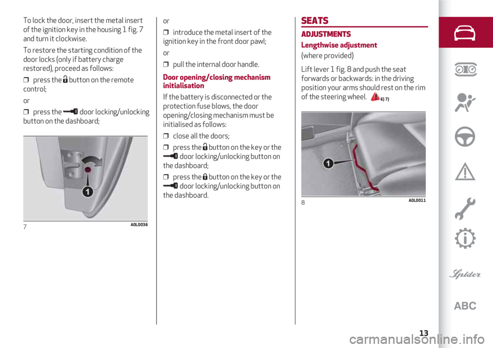
Lift lever 1 fig. 8 and push the seat
forwards or backwards: in the driving
position your arms should rest on the rim
of the steering wheel.
6) 7)
8A0L0011
To lock the door, insert the metal insert
of the ignition key in the housing 1 fig. 7
and turn it clockwise.
To restore the starting condition of the
door locks (only if battery charge
restored), proceed as follows:
❒ press the Ëbutton on the remote
control;
or
❒ press the ≈door locking/unlocking
button on the dashboard;
7A0L0036
or
❒ introduce the metal insert of the
ignition key in the front door pawl;
or
❒ pull the internal door handle.
Door opening/closing mechanism
initialisation
If the battery is disconnected or the
protection fuse blows, the door
opening/closing mechanism must be
initialised as follows:
❒ close all the doors;
❒ press the Ëbutton on the key or the
≈door locking/unlocking button on
the dashboard;
❒ press the Ábutton on the key or the
≈door locking/unlocking button on
the dashboard.
Page 22 of 156
KNOWING YOUR CAR
20
CLIMATE CONTROL
HEATING AND VENTILATION
2)
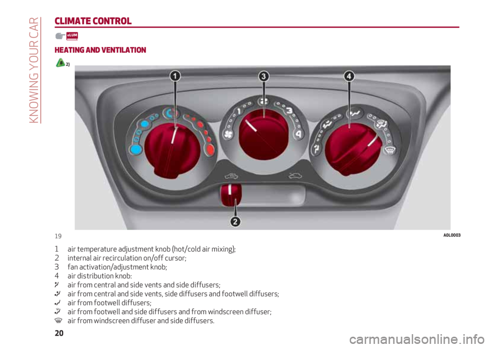
1 air temperature adjustment knob (hot/cold air mixing);
2 internal air recirculation on/off cursor;
3 fan activation/adjustment knob;
4 air distribution knob:
μair from central and side vents and side diffusers;
∑air from central and side vents, side diffusers and footwell diffusers;
∂air from footwell diffusers;
∏air from footwell and side diffusers and from windscreen diffuser;
-air from windscreen diffuser and side diffusers.
19A0L0003
Page 24 of 156
KNOWING YOUR CAR
22 Knob 4 enables the air introduced into the vehicle to reach all areas of the passenger compartment through five distribution
options:
μair from central and side vents and side diffusers;
∑air from central and side vents, side diffusers and footwell diffusers;
∂air from footwell diffusers;
∏air from footwell and side diffusers and from windscreen diffuser;
-air from windscreen diffuser and side diffusers.
2)The system uses a coolant that is compatible with the laws in force in the countries where the vehicle is sold, R134a or R-1234yf (indicated
on a specific plate in the engine compartment). The use of other coolants affects the efficiency and condition of the system. Also the
compressor coolants used must be compatible with the indicated coolant.
IMPORTANT
Page 25 of 156
23
ELECTRIC WINDOWS
These operate when the ignition key is
turned to MAR and for about three
minutes after the ignition key is turned to
STOP or removed unless one of the doors
is opened.
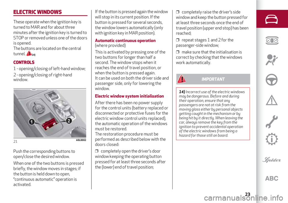
The buttons are located on the central
tunnel.
14)
CONTROLS
1 - opening/closing of left-hand window;
2 - opening/closing of right-hand
window.
Push the corresponding buttons to
open/close the desired window.
When one of the two buttons is pressed
briefly, the window moves in stages; if
the button is held down to open,
“continuous automatic” operation is
activated.
21A0L0002
If the button is pressed again the window
will stop in its current position. If the
button is pressed for several seconds,
the window lowers automatically (only
with ignition key in MAR position).
Automatic continuous operation (where provided)
This is activated by pressing one of the
two buttons for longer than half a
second. The window stops when it
reaches the end of travel position, or
when the button is pressed again.
It can be used on both the driver side and
passenger side, only for lowering the
window.
Electric window system initialisation
After there has been no power supply
for the control units (battery replaced or
disconnected or protective fuses for the
electric window control units replaced),
the automatic operation of the windows
must be restored.
The restoration procedure must be
performed as described below with the
doors closed:
❒ completely open the driver’s door
window keeping the operating button
pressed for at least three seconds after
the (lower) end of travel position;❒ completely raise the driver’s side
window and keep the button pressed for
at least three seconds once the end of
travel position (upper end stop) has been
reached;
❒ repeat stages 1 and 2 for the
passenger-side window;
❒ make sure that the initialisation is
correct by checking that the windows
work automatically.
14)Incorrect use of the electric windows
may be dangerous. Before and during
their operation, ensure that any
passengers are not at risk from the
moving glass either by personal objects
getting caught in the mechanism or by
being hit by it directly. When leaving the
car, always remove the key from the
ignition to prevent accidental operation
of the electric windows from being a
hazard for those still on board.
IMPORTANT
Page 47 of 156
45
Warning lights on panelMeaningWhat to do
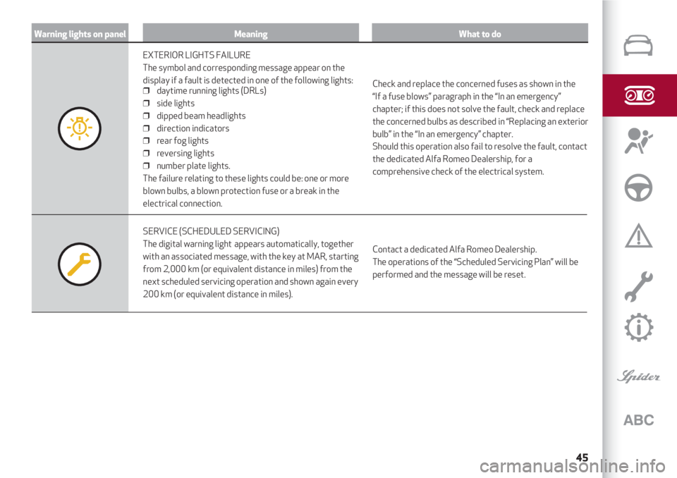
EXTERIOR LIGHTS FAILURE
The symbol and corresponding message appear on the
display if a fault is detected in one of the following lights:
❒ daytime running lights (DRLs)
❒ side lights
❒ dipped beam headlights
❒ direction indicators
❒ rear fog lights
❒ reversing lights
❒ number plate lights.
The failure relating to these lights could be: one or more
blown bulbs, a blown protection fuse or a break in the
electrical connection.
Check and replace the concerned fuses as shown in the
“If a fuse blows” paragraph in the “In an emergency”
chapter; if this does not solve the fault, check and replace
the concerned bulbs as described in “Replacing an exterior
bulb” in the “In an emergency” chapter.
Should this operation also fail to resolve the fault, contact
the dedicated Alfa Romeo Dealership, for a
comprehensive check of the electrical system.
SERVICE (SCHEDULED SERVICING)
The digital warning light appears automatically, together
with an associated message, with the key at MAR, starting
from 2,000 km (or equivalent distance in miles) from the
next scheduled servicing operation and shown again every
200 km (or equivalent distance in miles).Contact a dedicated Alfa Romeo Dealership.
The operations of the “Scheduled Servicing Plan” will be
performed and the message will be reset.
Page 49 of 156
47
Warning lights on panelMeaningWhat to do
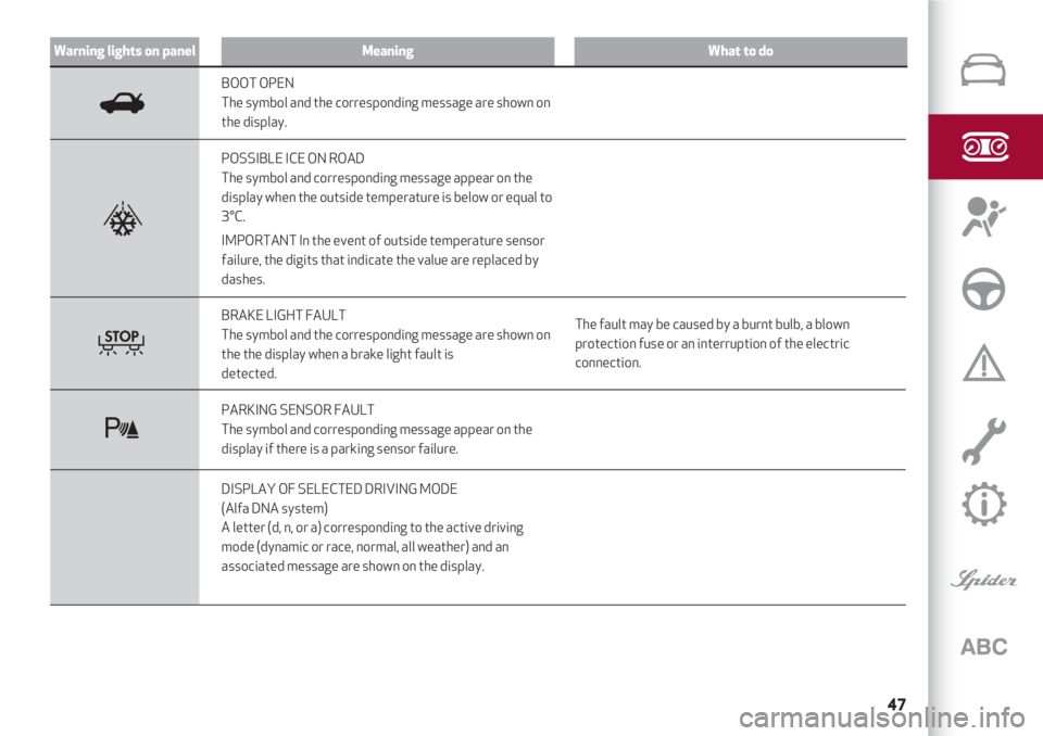
BOOT OPEN
The symbol and the corresponding message are shown on
the display.
POSSIBLE ICE ON ROAD
The symbol and corresponding message appear on the
display when the outside temperature is below or equal to
3°C.
IMPORTANT In the event of outside temperature sensor
failure, the digits that indicate the value are replaced by
dashes.
BRAKE LIGHT FAULT
The symbol and the corresponding message are shown on
the the display when a brake light fault is
detected.The fault may be caused by a burnt bulb, a blown
protection fuse or an interruption of the electric
connection.
PARKING SENSOR FAULT
The symbol and corresponding message appear on the
display if there is a parking sensor failure.
DISPLAY OF SELECTED DRIVING MODE
(Alfa DNA system)
A letter (d, n, or a) corresponding to the active driving
mode (dynamic or race, normal, all weather) and an
associated message are shown on the display.
R
T
t
Page 83 of 156
IN AN EMERGENCY
HAZARD LIGHTS ...................................................................................................... 82
WHEN NEEDING TO CHANGE A BULB ........................................................ 82
REPLACING AN EXTERNAL BULB .................................................................. 84
REPLACING FUSES ................................................................................................ 87
IF A TYRE IS PUNCTURED................................................................................... 90
“FIX&GO AUTOMATIC” KIT ................................................................................. 94
EMERGENCY STARTING ..................................................................................... 97
FUEL CUT-OFF SYSTEM ...................................................................................... 98
TOWING THE VEHICLE . ........................................................................................ 99
A punctured tyre or a burnt-out bulb?
At times, a problem may interfere with our journey.
The pages on emergencies can help you to deal with critical
situations independently and with calm.
In an emergency we recommend you call the freephone number
found in the Warranty Booklet. It is also possible
to call the national or international
universal freephone number to search
for the nearest dedicated Alfa Romeo Dealership.
Page 84 of 156
IN AN EMERGENCY
82
HAZARD WARNING LIGHTS
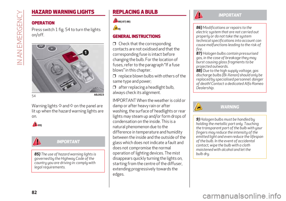
OPERATION
Press switch 1 fig. 54 to turn the lights
on/off.
Warning lights Ÿand Δon the panel are
lit up when the hazard warning lights are
on.
85)
54A0L0023
REPLACING A BULB
86) 87) 88)
9)
GENERAL INSTRUCTIONS
❒ Check that the corresponding
contacts are not oxidised and that the
corresponding fuse is intact before
changing the bulb. For the location of
fuses, refer to the paragraph “If a fuse
blows” in this chapter.
❒ replace blown bulbs with others of the
same type and power;
❒ after replacing a headlight bulb,
always check its alignment.
IMPORTANT When the weather is cold or
damp or after heavy rain or after
washing, the surface of headlights or rear
lights may steam up and/or form drops of
condensation on the inside. This is a
natural phenomenon due to the
difference in temperature and humidity
between the inside and the outside of the
glass which does not indicate a fault and
does not compromise the normal
operation of lighting devices. The mist
disappears quickly turning the lights on,
starting from the centre of the diffuser,
extending progressively towards the
edges.
85)The use of hazard warning lights is
governed by the Highway Code of the
country you are driving in: comply with
legal requirements.
IMPORTANT
86)Modifications or repairs to the
electric system that are not carried out
properly or do not take the system
technical specifications into account can
cause malfunctions leading to the risk of
fire.
87) Halogen bulbs contain pressurised
gas, in the case of breakage they may
burst causing glass fragments to be
projected outwards.
88) Due to the high supply voltage, gas
discharge bulbs (Bi-Xenon) should only be
replaced by specialised personnel: danger
of death! Contact a dedicated Alfa Romeo
Dealership.
IMPORTANT
9)Halogen bulbs must be handled by
holding the metallic part only. Touching
the transparent part of the bulb with your
fingers may reduce the intensity of the
emitted light and even reduce the lifespan
of the bulb. In the event of accidental
contact, wipe the bulb with a cloth
moistened with alcohol and let the
bulb dry.
WARNING
Page 89 of 156
87
NUMBER PLATE LIGHTS
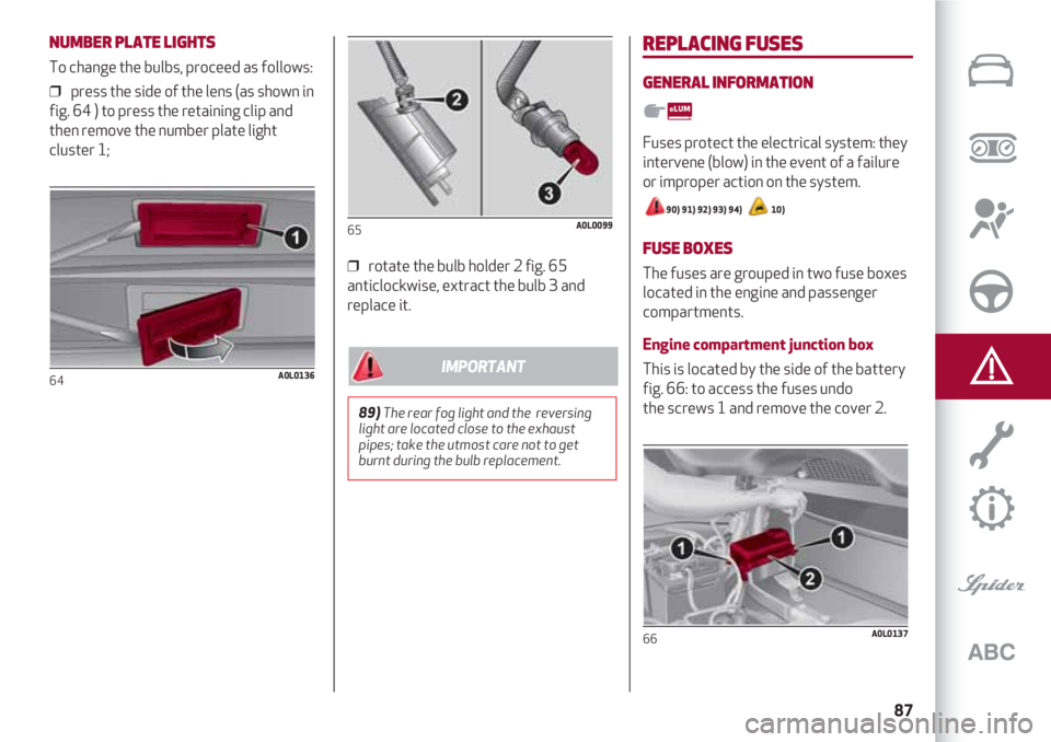
To change the bulbs, proceed as follows:
❒ press the side of the lens (as shown in
fig. 64 ) to press the retaining clip and
then remove the number plate light
cluster 1;
64A0L0136
❒ rotate the bulb holder 2 fig. 65
anticlockwise, extract the bulb 3 and
replace it.
65A0L0099
REPLACING FUSES
GENERAL INFORMATION
Fuses protect the electrical system: they
intervene (blow) in the event of a failure
or improper action on the system.
90) 91) 92) 93) 94) 10)
FUSE BOXES
The fuses are grouped in two fuse boxes
located in the engine and passenger
compartments.
Engine compartment junction box
This is located by the side of the battery
fig. 66: to access the fuses undo
the screws 1 and remove the cover 2.
66A0L0137
89)The rear fog light and the reversing
light are located close to the exhaust
pipes; take the utmost care not to get
burnt during the bulb replacement.
IMPORTANT
Page 90 of 156
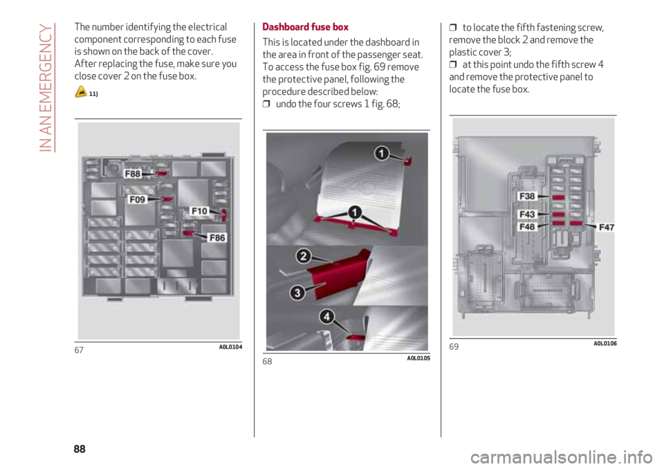
The number identifying the electrical
component corresponding to each fuse
is shown on the back of the cover.
After replacing the fuse, make sure you
close cover 2 on the fuse box.
11)
67A0L0104
Dashboard fuse box
This is located under the dashboard in
the area in front of the passenger seat.
To access the fuse box fig. 69 remove
the protective panel, following the
procedure described below:
❒ undo the four screws 1 fig. 68;
68A0L0105
❒ to locate the fifth fastening screw,
remove the block 2 and remove the
plastic cover 3;
❒ at this point undo the fifth screw 4
and remove the protective panel to
locate the fuse box.
69A0L0106
IN AN EMERGENCY
88