ignition Alfa Romeo Brera/Spider 2007 Owner handbook (in English)
[x] Cancel search | Manufacturer: ALFA ROMEO, Model Year: 2007, Model line: Brera/Spider, Model: Alfa Romeo Brera/Spider 2007Pages: 271, PDF Size: 6.04 MB
Page 44 of 271

Lumbar adjustment
(where provided)
Turn the knob Duntil obtaining the re-
quired position.
Back rest angle adjustment
(where provided)
Use lever E. Pulling the lever upwards
the seat will bend back by one position.
Pushing the lever downwards the seat
will bend forward.
Tilting the back rest
To get to the rear seats, pull handle F:
the back rest will tilt and the seat can
slide forward.
Bringing back the back rest the seat will
return automatically to its original posi-
tion (mechanical memory).
After bringing the back rest to its origi-
nal position check tat it firmly locked.
Check also that the seat is firmly locked
in the runners by trying to move it back
and forth.
42
SAFETY
DEVICES
WARNING
LIGHTS AND
MESSAGES
IN AN
EMERGENCY
CAR
MAINTENANCE
TECHNICAL
SPECIFICATIONS
INDEX
DASHBOARD
AND
CONTROLS
CORRECT USE
OF THE CAR
ELECTRICALLY ADJUSTABLE
FRONT SEATS (where
provided) fig. 27
Seat controls are the
following:
Multifunction control A:
❒front seat height adjustment;
❒rear seat height adjustment;
❒vertical seat movement;
❒longitudinal seat movement;
B:Back rest angle adjustment;
C:Driver’s seat positions store buttons;
D:Lumbar adjustment;
E:Back rest tipping.
IMPORTANTSeat can only be ad-
justed when the electronic key is fitted
into the ignition device and for about 1
minute from removing it or after press-
ing button START/STOP. After open-
ing the door the seat can be adjusted for
about 3 minutes or until closing the
door.
Only make adjustments
when the car is station-
ary.
WARNING
A0F0189mfig. 27
Page 45 of 271
43
SAFETY
DEVICES
WARNING
LIGHTS AND
MESSAGES
IN AN
EMERGENCY
CAR
MAINTENANCE
TECHNICAL
SPECIFICATIONS
INDEX
DASHBOARD
AND
CONTROLS
CORRECT USE
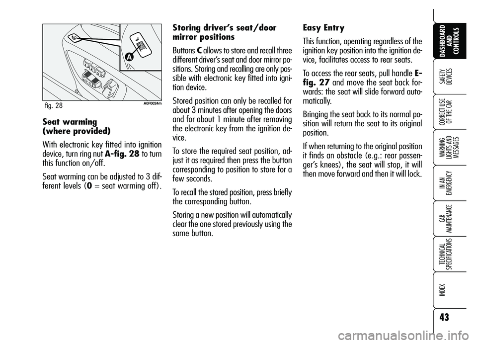
OF THE CARSeat warming
(where provided)
With electronic key fitted into ignition
device, turn ring nut A-fig. 28 to turn
this function on/off.
Seat warming can be adjusted to 3 dif-
ferent levels (0= seat warming off).
A0F0024mfig. 28
Easy Entry
This function, operating regardless of the
ignition key position into the ignition de-
vice, facilitates access to rear seats.
To access the rear seats, pull handle E-
fig. 27and move the seat back for-
wards: the seat will slide forward auto-
matically.
Bringing the seat back to its normal po-
sition will return the seat to its original
position.
If when returning to the original position
it finds an obstacle (e.g.: rear passen-
ger’s knees), the seat will stop, it will
then move forward and then it will lock. Storing driver’s seat/door
mirror positions
Buttons Callows to store and recall three
different driver’s seat and door mirror po-
sitions. Storing and recalling are only pos-
sible with electronic key fitted into igni-
tion device.
Stored position can only be recalled for
about 3 minutes after opening the doors
and for about 1 minute after removing
the electronic key from the ignition de-
vice.
To store the required seat position, ad-
just it as required then press the button
corresponding to position to store for a
few seconds.
To recall the stored position, press briefly
the corresponding button.
Storing a new position will automatically
clear the one stored previously using the
same button.
Page 48 of 271

46
SAFETY
DEVICES
WARNING
LIGHTS AND
MESSAGES
IN AN
EMERGENCY
CAR
MAINTENANCE
TECHNICAL
SPECIFICATIONS
INDEX
DASHBOARD
AND
CONTROLS
CORRECT USE
OF THE CARAdjusting the mirror
Use device A-fig. 34to select the re-
quired mirror:
❒turn selector Ato 1: to select the
left mirror;
❒turn selector Ato 2: to select the
right mirror.
To adjust the mirror move the switch B
in the four directions shown by the ar-
rows.
IMPORTANTAfter adjusting the mir-
ror, turn selector Ato 0to prevent ac-
cidental movements.
DOOR MIRRORS
Door mirror can only be adjusted and
folded when the electronic key is fitted
into the ignition device.
A0F0135mfig. 32
REARVIEW
MIRRORS
DRIVING MIRROR
The mirror is fitted with a safety device
that causes it to be released in the event
of a violent crash.
Using lever A-fig. 32the mirror can
be adjusted to two different positions:
normal or antiglare.
A0F0036mfig. 34
Page 49 of 271
47
SAFETY
DEVICES
WARNING
LIGHTS AND
MESSAGES
IN AN
EMERGENCY
CAR
MAINTENANCE
TECHNICAL
SPECIFICATIONS
INDEX
DASHBOARD
AND
CONTROLS
CORRECT USE
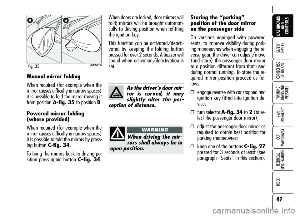
OF THE CARManual mirror folding
When required (for example when the
mirror causes difficulty in narrow spaces)
it is possible to fold the mirror moving it
from position A-fig. 35 to position B.
Powered mirror folding
(where provided)
When required (for example when the
mirror causes difficulty in narrow spaces)
it is possible to fold the mirrors by press-
ing button C-fig. 34.
To bring the mirrors back to driving po-
sition press again button C-fig. 34.
A0F0081mfig. 35
As the driver’s door mir-
ror is curved, it may
slightly alter the per-
ception of distance.
When driving the mir-
rors shall always be in
open position.
WARNING
When doors are locked, door mirrors will
fold; mirrors will be brought automati-
cally to driving position when refitting
the ignition key.
This function can be activated/deacti-
vated by keeping the folding button
pressed for over 2 seconds. A buzzer will
sound when activation/deactivation is
set.Storing the “parking”
position of the door mirror
on the passenger side
On versions equipped with powered
seats, to improve visibility during park-
ing manoeuvres when engaging the re-
verse gear, the driver can adjust/move
(and store) the passenger door mirror
to a position different from that used
during normal running. To store the re-
quired mirror position proceed as fol-
lows:
❒engage reverse with car stopped and
ignition key fitted into ignition de-
vice;
❒turn selector A-fig. 34 to2(to se-
lect the passenger door mirror);
❒adjust the passenger door mirror as
required to obtain best position for
parking manoeuvres;
❒keep one of the buttons C-fig. 27
pressed for 3 seconds at least (see
paragraph “Seats” in this section).
Page 50 of 271
48
SAFETY
DEVICES
WARNING
LIGHTS AND
MESSAGES
IN AN
EMERGENCY
CAR
MAINTENANCE
TECHNICAL
SPECIFICATIONS
INDEX
DASHBOARD
AND
CONTROLS
CORRECT USE
OF THE CAR
Together with the passenger door mir-
ror “parking” position, also the driver
seat and door mirror positions will be
stored. The sound of a buzzer confirms
that the mirror position has been stored.Recallig the passenger door
mirror “parking”
Proceed as follows: fit the electronic key
into the ignition device; engage reverse;
turn selectorA-fig. 34to 2(to select
the passenger door mirror).
The mirror will set automatically to the
previously stored position.
If no parking position has been stored,
when engaging reverse the passenger
door mirror will slightly lower to aid the
driver during parking.
The mirror will automatically return to
its original position 10 seconds after dis-
engaging reverse, when the car speed
exceeds 10 km/h in forward gear or
when turning selector A-fig. 34to 0.Automatic door mirror
realignment
Each time the ignition key is fitted into
the ignition device, door mirrors return
automatically to the last position
reached and/or recalled at last key re-
moval.
This enables mirror alignment if when
leaving the car parked one of the door
mirrors has been moved manually
and/or accidentally.
Defrosting/demisting
The electric mirrors are fitted with heating
coils which come into operation when turn-
ing on the heated rear window (by press-
ing button
().
IMPORTANTThis function is timed
and is deactivated after a few minutes.
Page 55 of 271
53
SAFETY
DEVICES
WARNING
LIGHTS AND
MESSAGES
IN AN
EMERGENCY
CAR
MAINTENANCE
TECHNICAL
SPECIFICATIONS
INDEX
DASHBOARD
AND
CONTROLS
CORRECT USE
OF THE CAR
CLIMATE CONTROL
(fast cooling)
IMPORTANTThe compressor √can
be enabled only if the ventilation is en-
abled.
Proceed as follows:
❒turn knob Acompletely leftwards;
❒turn knob Cto top speed;
❒turn knob Bto O;
❒press buttons √and v(buttons
leds on).
How to keep the required
cooling
Proceed as follows:
❒turn air recirculation off (if on).
❒turn knob Ato the required tem-
perature;
❒turn the knurled ring C to the re-
quired fan speed.
LOOKING AFTER
THE SYSTEM
During the winter, the climate control
system
√must be turned on at least
once a month for about ten minutes.
Before summer, have the system
checked at Alfa Romeo Authorized Ser-
vices.
RECIRCULATION
To turn this function on press button
v: the button led will turn on.
This function is particularly useful when
the outside air is heavily polluted (in a
traffic jam, tunnel, etc.) However, it is
better not to use it for long periods, es-
pecially if there are several people in the
car to prevent window misting up.
Do not use the air recirculation function
on rainy/cold days as it would consid-
erably increase the possibility of the win-
dows misting inside.
IMPORTANTThe inside air recircula-
tion system makes it possible to reach
the required (“heating” or “cooling”)
conditions faster.
After connecting/dis-
connecting the battery,
wait for 3 minutes at
least before fitting the elec-
tronic key into the ignition de-
vice in order to allow the cli-
mate control system control unit
to reset the positions of the
electric actuators that adjust air
temperature and distribution.
Page 63 of 271
61
SAFETY
DEVICES
WARNING
LIGHTS AND
MESSAGES
IN AN
EMERGENCY
CAR
MAINTENANCE
TECHNICAL
SPECIFICATIONS
INDEX
DASHBOARD
AND
CONTROLS
CORRECT USE
OF THE CAR
AIR DISTRIBUTION
SELECTION
Pressing buttons N/O/˙you can
manually choose one of the 7 possible
modes for air distribution inside the com-
partment:
˙Flow of air to the dashboard centre
and side outlets (passenger’s body).
O˙Splitting of the air flow between
the vents to the lower part of the
passenger compartment (warmest
air) and the dashboard centre and
side outlets (coolest air).
OAir flow towards the lower part of the
passenger compartment. This type
of distribution allows heating of the
passenger compartment in the short-
est time.
NSplitting of the air flow between
Owindscreen and front side window
demisting/defrosting vents and the
lower part of the passenger com-
partment. This type of air distribu-
tion allows satisfactory heating of
the passenger compartment while
preventing possible misting of the
windows.
NAir flow to the windscreen and front
side window vents to demist or de-
frost them.
N˙Splitting of the air flow between
the central/side dashboard vents
and windscreen and side window
defrosting/demisting vents. This
type of air distribution allows satis-
factory ventilation of the passenger
compartment while preventing pos-
sible misting of the windows.
N˙Splitting of the air flow between
all vents.
O
To restore automatic air distribution con-
trol after a manual selection, press but-
ton AUTO. Temperature detection (compressor off
and outside temperature higher than set
temperature) is activated each time the
electronic key is fitted into the ignition
device.
Operation of the cli-
mate control compres-
sor is necessary for cooling
and dehumidifying the air; it is
advisable to keep this function
always on, to prevent window
misting problems.
WARNING
Page 66 of 271
64
SAFETY
DEVICES
WARNING
LIGHTS AND
MESSAGES
IN AN
EMERGENCY
CAR
MAINTENANCE
TECHNICAL
SPECIFICATIONS
INDEX
DASHBOARD
AND
CONTROLS
CORRECT USE
OF THE CAR
SWITCHING THE CLIMATE
CONTROL SYSTEM OFF
Keep pressed button “–“ until the dis-
play shows OFF.
With climate control system off:
❒the system stores performed opera-
tions;
❒the display is off (OFF wording is dis-
played);
❒air recirculation is active (button led
on);
❒compressor is active;
❒ventilation is off.
To turn the climate control system on
again press button AUTO or any other
button (excluding
(, vand
MONO). Turning the climate control sys-
tem on again, air recirculation will be
again controlled automatically.
ADDITIONAL
HEATER (diesel
versions only)
(where provided)
The car is fitted with an additional heater
that supports the engine during cold or
winter weather to quickly reach a com-
fortable temperature in the passenger
compartment.
The additional heater works with the en-
gine running when the outside temper-
ature is below 20°C and the engine has
not yet reached normal operating tem-
perature.
After connecting/dis-
connecting the battery,
wait for 3 minutes at
least before fitting the elec-
tronic key into the ignition de-
vice in order to allow the cli-
mate control system control unit
to reset the positions of the
electric actuators that adjust air
temperature and distribution.
Page 67 of 271
65
SAFETY
DEVICES
WARNING
LIGHTS AND
MESSAGES
IN AN
EMERGENCY
CAR
MAINTENANCE
TECHNICAL
SPECIFICATIONS
INDEX
DASHBOARD
AND
CONTROLS
CORRECT USE
OF THE CAR
EXTERNAL LIGHTS
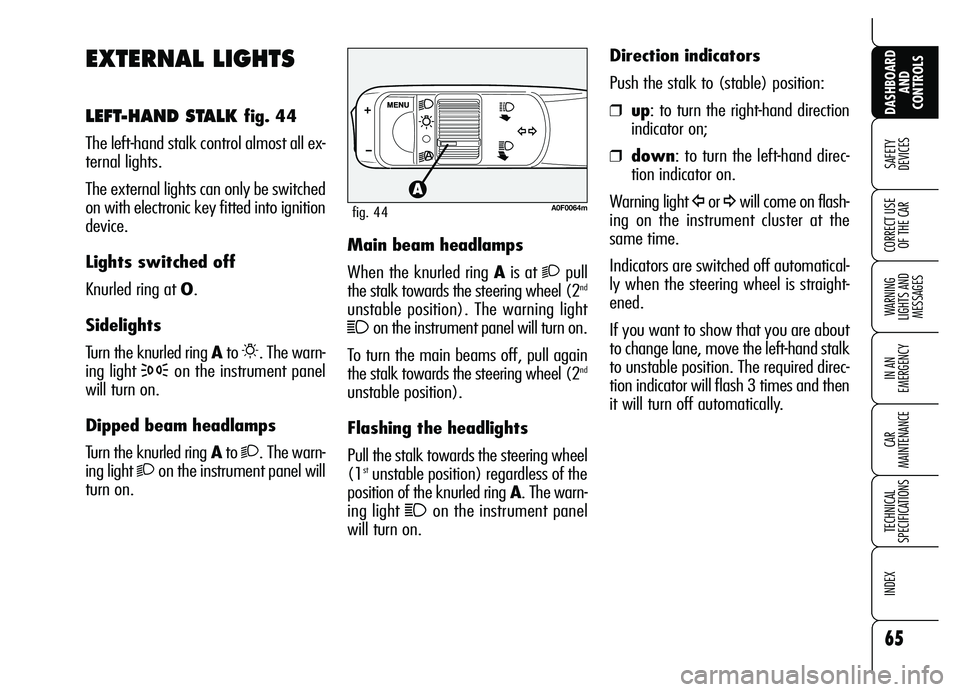
LEFT-HAND STALK fig. 44
The left-hand stalk control almost all ex-
ternal lights.
The external lights can only be switched
on with electronic key fitted into ignition
device.
Lights switched off
Knurled ring at O.
Sidelights
Turn the knurled ring Ato
6. The warn-
ing light
3on the instrument panel
will turn on.
Dipped beam headlamps
Turn the knurled ring Ato
2. The warn-
ing light
2on the instrument panel will
turn on.Main beam headlamps
When the knurled ring Ais at
2pull
the stalk towards the steering wheel (2nd
unstable position). The warning light
1on the instrument panel will turn on.
To turn the main beams off, pull again
the stalk towards the steering wheel (2
nd
unstable position).
Flashing the headlights
Pull the stalk towards the steering wheel
(1
stunstable position) regardless of the
position of the knurled ring A. The warn-
ing light
1on the instrument panel
will turn on.Direction indicators
Push the stalk to (stable) position:
❒up: to turn the right-hand direction
indicator on;
❒down: to turn the left-hand direc-
tion indicator on.
Warning light
Îor ¥will come on flash-
ing on the instrument cluster at the
same time.
Indicators are switched off automatical-
ly when the steering wheel is straight-
ened.
If you want to show that you are about
to change lane, move the left-hand stalk
to unstable position. The required direc-
tion indicator will flash 3 times and then
it will turn off automatically.A0F0064mfig. 44
Page 72 of 271
70
SAFETY
DEVICES
WARNING
LIGHTS AND
MESSAGES
IN AN
EMERGENCY
CAR
MAINTENANCE
TECHNICAL
SPECIFICATIONS
INDEX
DASHBOARD
AND
CONTROLS
CORRECT USE
OF THE CAR
Rain sensor shall be de-
activated when washing
the car at automatic car-
wash.
Make sure the rain sen-
sor is deactivated if
there is ice on the wind-
screen.
Removing the electronic key from the
ignition device, the rain sensor is deac-
tivated and the next time the engine is
started it will not be reactivated even if
the stalk has remained in position 1-
fig. 47. In this case to activate the rain
sensor, simply move the stalk to 0or 2
and then back to 1.
When the rain sensor is reactivated in
this way, the wiper performs one stroke,
even if the windscreen is dry, to indicate
that reactivation has occurred.IMPORTANTIn the event of rain sen-
sor failure, windscreen wiper operation
with right-hand stalk at 1-fig. 47is in-
termittent. If failure takes place during
automatic operation, the system will
keep the last wiper operating condition.
Moving the stalk to other positions, op-
eration is however guaranteed.
The rain sensor is able to recognize and
automatically adjust itself in the pres-
ence of the following particular condi-
tions:
❒impurities on the controlled surface
(salt, dirt, etc.);
❒difference between day and night.Failure warnings
Sensor failure is indicated by a dedicat-
ed message on the display (see section
“Warning lights and messages”).