ESC Alfa Romeo Brera/Spider 2007 Owner handbook (in English)
[x] Cancel search | Manufacturer: ALFA ROMEO, Model Year: 2007, Model line: Brera/Spider, Model: Alfa Romeo Brera/Spider 2007Pages: 271, PDF Size: 6.04 MB
Page 3 of 271
This Owner’s Manual describes all the versions of the Alfa Brera, so you should only consider the
information concerning the trim level, engine and version purchased by you.
Dear Customer,
thank you for choosing Alfa Romeo.
Your
Alfa Brerahas been designed to guarantee the safety, comfort and driving pleasure typical of
Alfa Romeo.
This booklet will help you to get to know the characteristics and operation of your car.
The following pages contain all the indications necessary for you to be able to maintain the high standards of per-
formance, quality, safety and respect for the environment which characterize your
Alfa Brera.
The enclosed Warranty Booklet also contains the regulations, the warranty certificate and a guide to the services of-
fered by Alfa Romeo.
Services which are essential and precious because, when you purchase an Alfa Romeo you are not only acquiring a
car, but the tranquillity that comes from knowing that an efficient, willing and widespread organization is at your ser-
vice for any assistance problems you may have.
Have a good trip.
Page 6 of 271
Any queries concerning servicing should be forwarded to the showroom from which the car was purchased, the sub-
sidiary company or to our branch offices or any point of the Alfa Romeo Network.
Warranty Booklet
The Warranty Booklet is delivered together with every new car and contains the regulations tied to the services giv-
en by Alfa Romeo Services and to the warranty conditions.
Correctly carrying out the scheduled services specified by the manufacturer is the best way to maintain the perfor-
mance, safety characteristics and low running costs of your car. It is also necessary to maintain warranty cover.
“Service” guide
This contains the Alfa Romeo Authorized Services. The services can be recognized by the presence of the Alfa Romeo
badge and logo.
The Alfa Romeo organization in Italy can be found in the telephone book under the letter “A” Alfa Romeo.
Not all the models described in this booklet are available in all countries. Only some of the fittings described in this
booklet are fitted as standard to the car. The list of available accessories should be requested from the Alfa Romeo
Dealers.
Page 29 of 271
27
SAFETY
DEVICES
WARNING
LIGHTS AND
MESSAGES
IN AN
EMERGENCY
CAR
MAINTENANCE
TECHNICAL
SPECIFICATIONS
INDEX
DASHBOARD
AND
CONTROLS
CORRECT USE
OF THE CAR
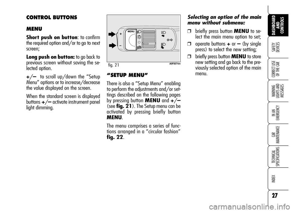
A0F0074mfig. 21
“SETUP MENU”
There is also a “Setup Menu” enabling
to perform the adjustments and/or set-
tings described on the following pages
by pressing button MENUand +/–
(see fig. 21). The Setup menu can be
activated by pressing briefly button
MENU.
The menu comprises a series of func-
tions arranged in a “circular fashion”
fig. 22.Selecting an option of the main
menu without submenu:
❒briefly press button MENUto se-
lect the main menu option to set;
❒operate buttons +or –(by single
press) to select the new setting;
❒briefly press button MENU to store
new setting and go back to the pre-
viously selected option of the main
menu.
CONTROL BUTTONS
MENU
Short push on button: to confirm
the required option and/or to go to next
screen;
Long push on button:to go back to
previous screen without saving the se-
lected option.
+/– to scroll up/down the “Setup
Menu” options or to increase/decrease
the value displayed on the screen.
When the standard screen is displayed
buttons+/– activate instrument panel
light dimming.
Page 32 of 271
30
SAFETY
DEVICES
WARNING
LIGHTS AND
MESSAGES
IN AN
EMERGENCY
CAR
MAINTENANCE
TECHNICAL
SPECIFICATIONS
INDEX
DASHBOARD
AND
CONTROLS
CORRECT USE
OF THE CAR
Automatic headlight daylight
sensor (where provided)
(Light Sens.)
With this function it is possible to adjust
the light sensor sensitivity according to
3 levels.
To adjust the volume proceed as follows:
❒briefly press button MENU: the pre-
viously set level will be displayed;
❒press button +or –for setting as re-
quired;
❒briefly press buttonMENUto go
back to the menu screen or press the
button for long to go back to the
standard screen.
Reset Trip B
This function enables to select Trip B re-
set mode (Automatic or Manual).
For further information see paragraph
“Trip computer”. Speed limit (Speed limit)
With this function it is possible to set the
car speed limit (km/h or mph), which,
if exceeded, automatically sounds a
buzzer and displays a special message
(see section “Warning lights and mes-
sages”) to alert the driver.
To set the speed limit, proceed as fol-
lows:
❒briefly press button MENU: OFF
will be displayed;
❒press button +: ONwill be dis-
played;
❒briefly press button MENUthen,
use buttons +/–to set the required
speed (during setting the value will
flash).
❒briefly press button MENU to go
back to the menu screen or press the
button for long to go back to the
standard screen.IMPORTANTThe possible setting is
between 30 and 250 km/h (or be-
tween 20 and 150 mph) depending on
the unit set previously (see paragraph
“Units” described later). Every press
(pulse) of the button +/–increases or
decreases the value by 5 units. Keeping
the button +/–pressed obtains auto-
matic fast increase or decrease. When
you are near the required setting com-
plete adjustment with single presses.
To abort the setting:
❒briefly press button MENU: ON
will be displayed;
❒press button –: OFFwill be dis-
played;
❒briefly press button MENU to go
back to the menu screen or press the
button for long to go back to the
standard screen.
Page 56 of 271
54
SAFETY
DEVICES
WARNING
LIGHTS AND
MESSAGES
IN AN
EMERGENCY
CAR
MAINTENANCE
TECHNICAL
SPECIFICATIONS
INDEX
DASHBOARD
AND
CONTROLS
CORRECT USE
OF THE CARTo guarantee perfect
and regular sensor op-
eration do not apply
stickers in the “monitoring”
area between sensor and wind-
screen. Keep windscreen and
sensor clean and avoid to accu-
mulate dust or other sub-
stances.
AUTOMATIC
TWO-ZONE CLIMATE
CONTROL SYSTEM
(where provided)
DESCRIPTION
The car is fitted with a two-zone climate
control system which makes it possible
to separately adjust the air temperature
in the two passenger’s compartment ar-
eas to reach the required comfort.
To obtain top control of both zones, the
system is fitted with outside temperature
sensor, passenger’s compartment tem-
perature sensor and bilateral sun radia-
tion sensor.
The climate control system automatically
controls and adjusts the following pa-
rameters and functions:
❒air temperature at driver/passengers
vents;
❒fan speed;
❒air distribution at driver/passenger
vents;
❒compressor activation;
❒air recirculation.
The following parameters and functions
can be set or changed manually:
❒required temperature;
❒fan speed;
❒air distribution on seven levels;
❒compressor on/off;
❒window demisting/defrosting;
❒air recirculation;
❒one-zone function.
The system is fitted with AQS (Air Qual-
ity System) sensor (where provided),
that turns on air recirculation automati-
cally when it detects the presence of out-
side polluted air (for example in queues
and tunnels).
Where provided, the system is integrat-
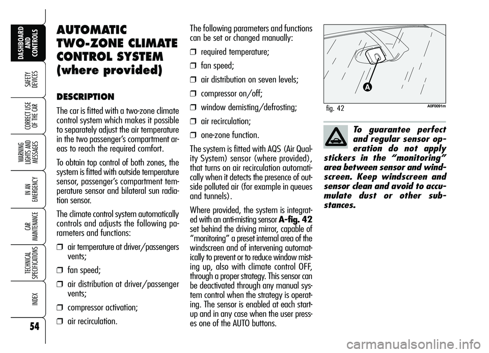
ed with an anti-misting sensor A-fig. 42
set behind the driving mirror, capable of
“monitoring” a preset internal area of the
windscreen and of intervening automat-
ically to prevent or to reduce window mist-
ing up, also with climate control OFF,
through a proper strategy. This sensor can
be deactivated through any manual sys-
tem control when the strategy is operat-
ing. The sensor is enabled at each start-
up and in any case when the user press-
es one of the AUTO buttons.
A0F0091mfig. 42
Page 91 of 271
89
SAFETY
DEVICES
WARNING
LIGHTS AND
MESSAGES
IN AN
EMERGENCY
CAR
MAINTENANCE
TECHNICAL
SPECIFICATIONS
INDEX
DASHBOARD
AND
CONTROLS
CORRECT USE
OF THE CAR
The system complies
with the forthcoming
Standard 2000/4/ EC
concerning the safety of pas-
sengers leaning out of the pas-
senger compartment.
For all versions, after unlocking the
doors, keeping the remote control but-
ton pressed for about 2 seconds will ob-
tain window and sunroof (where pro-
vided) opening.
A0F0051mfig. 70
CONTROLS
Driver side
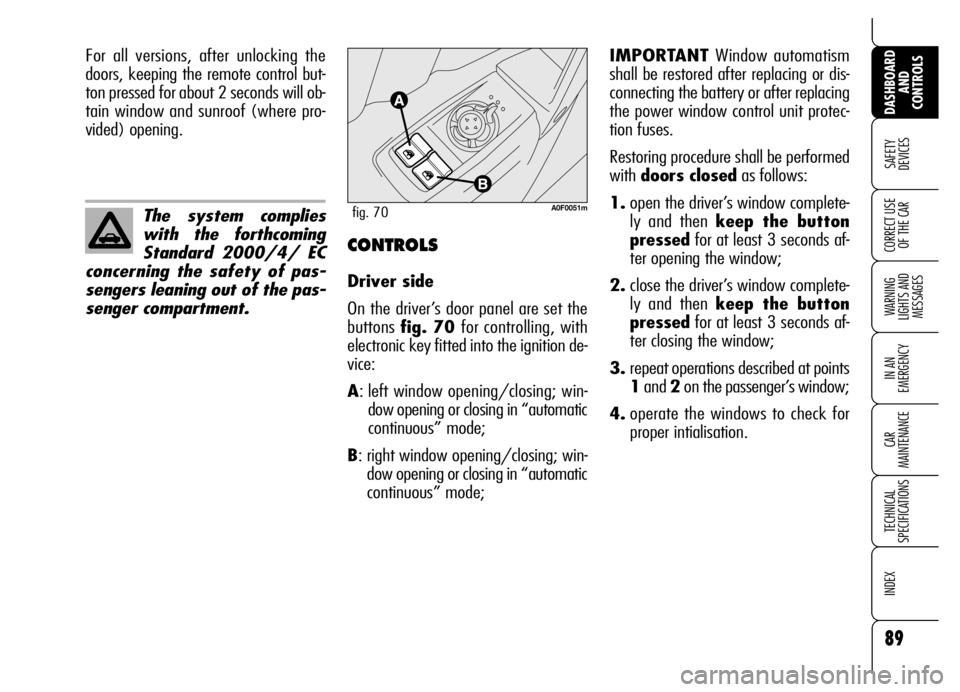
On the driver’s door panel are set the
buttons fig. 70 for controlling, with
electronic key fitted into the ignition de-
vice:
A: left window opening/closing; win-
dow opening or closing in “automatic
continuous” mode;
B: right window opening/closing; win-
dow opening or closing in “automatic
continuous” mode;IMPORTANTWindow automatism
shall be restored after replacing or dis-
connecting the battery or after replacing
the power window control unit protec-
tion fuses.
Restoring procedure shall be performed
with doors closedas follows:
1.open the driver’s window complete-
ly and then keep the button
pressedfor at least 3 seconds af-
ter opening the window;
2.close the driver’s window complete-
ly and then keep the button
pressedfor at least 3 seconds af-
ter closing the window;
3.repeat operations described at points
1and 2on the passenger’s window;
4.operate the windows to check for
proper intialisation.
Page 94 of 271
92
SAFETY
DEVICES
WARNING
LIGHTS AND
MESSAGES
IN AN
EMERGENCY
CAR
MAINTENANCE
TECHNICAL
SPECIFICATIONS
INDEX
DASHBOARD
AND
CONTROLS
CORRECT USE
OF THE CAREMERGENCY OPENING OF
THE BOOT FROM THE
PASSENGER COMPARTMENT
To open the tailgate from the inside if
the battery is flat or the electric tailgate
lock is failing, proceed as follows:
❒tilt the rear seats as described in
paragraph “Extending the boot” in
this section;
❒remove rear head restraints;
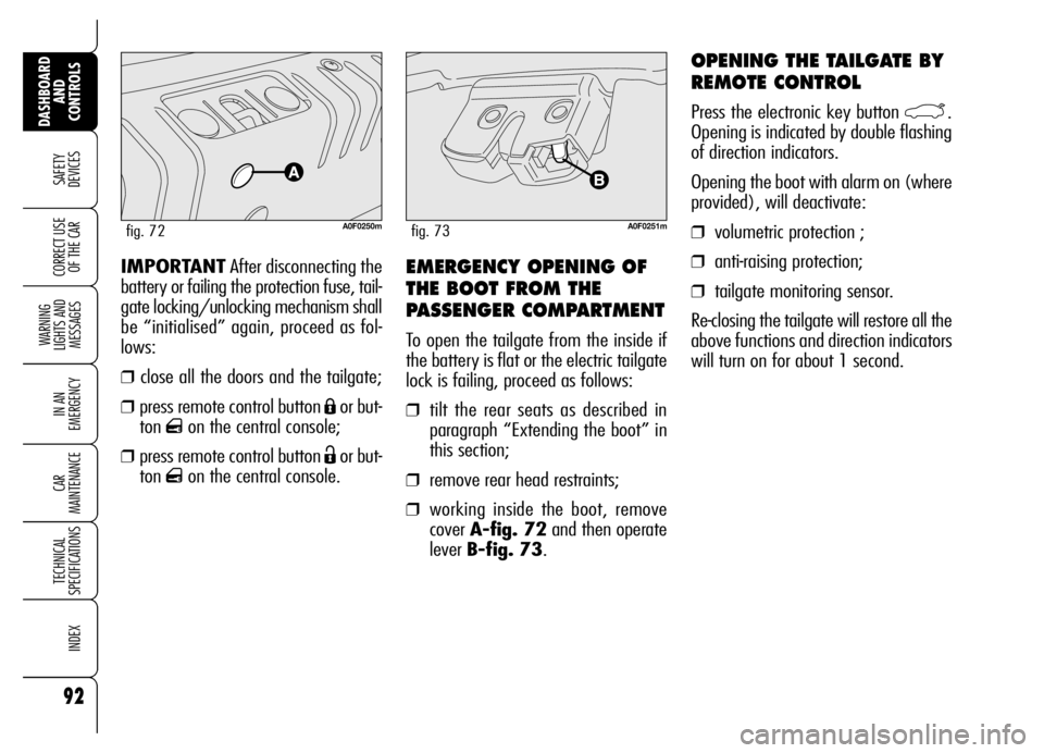
❒working inside the boot, remove
cover A-fig. 72and then operate
lever B-fig. 73. IMPORTANTAfter disconnecting the
battery or failing the protection fuse, tail-
gate locking/unlocking mechanism shall
be “initialised” again, proceed as fol-
lows:
❒close all the doors and the tailgate;
❒press remote control button Áor but-
ton
qon the central console;
❒press remote control button Ëor but-
ton
qon the central console.
A0F0250mfig. 72
OPENING THE TAILGATE BY
REMOTE CONTROL
Press the electronic key button `.
Opening is indicated by double flashing
of direction indicators.
Opening the boot with alarm on (where
provided), will deactivate:
❒volumetric protection ;
❒anti-raising protection;
❒tailgate monitoring sensor.
Re-closing the tailgate will restore all the
above functions and direction indicators
will turn on for about 1 second.
A0F0251mfig. 73
Page 123 of 271
121
Ù
SAFETY
DEVICES WARNING
LIGHTS AND
MESSAGES
IN AN
EMERGENCY
CAR
MAINTENANCE
TECHNICAL
SPECIFICATIONS
INDEX
DASHBOARD
AND
CONTROLS
CORRECT USE
OF THE CAR
The results of research on the best child
restraint systems are contained in the
European Standard ECE-R44. This Stan-
dard enforces the use of restraint sys-
tems classified in five groups:
Group 0 - 0-10 kg in weight
Group 0+ - 0-13 kg in weight
Group 1 9-18 kg in weight
Group 2 15-25 kg in weight
Group 3 22-36 kg in weight
As it may be noted, the groups overlap
partly and in fact, in commerce it is pos-
sible to find devices that cover more
than one weight group.
All restraint devices must bear the cer-
tification data, together with the control
brand, on a solidly fixed label which
must absolutely never be removed.
Over 1.50 m in height, from the point
of view of restraint systems, children are
considered as adults and wear the seat
belts normally.Lineaccessori Alfa Romeo offers seats for
each weight group, which are the rec-
ommended choice, as they have been
designed and experimented specifical-
ly for Alfa Romeo cars.CARRYING
CHILDREN SAFELY
For optimal protection in the event of
a crash, all passengers must be seated
and wearing adequate restraint systems.
This is even more important for children.
This prescription is compulsory in all EC
countries according to EC Directive
2003/20/EC.
Compared with adults, a child’s head is
proportionately larger and heavier than
the rest of the body, while muscles and
bone structure are not completely de-
veloped. Therefore, in order to restraint
them correctly in the event of a crash,
different systems are needed than adult
seat belts.
With passenger’s air
bag active, never place
child’s seats with the cradle
facing backwards since the air
bag activation could cause to
the child serious injuries, even
mortal, regardless of the seri-
ousness of the crash that trig-
gered it. You are advised to
carry children always with
proper restraint systems on
the rear seats, as this is the
most protected position in the
case of a crash.
WARNING
Page 177 of 271
175
SAFETY
DEVICES
WARNING
LIGHTS AND
MESSAGES
IN AN
EMERGENCY CAR
MAINTENANCE
TECHNICAL
SPECIFICATIONS
INDEX
DASHBOARD
AND
CONTROLS
CORRECT USE
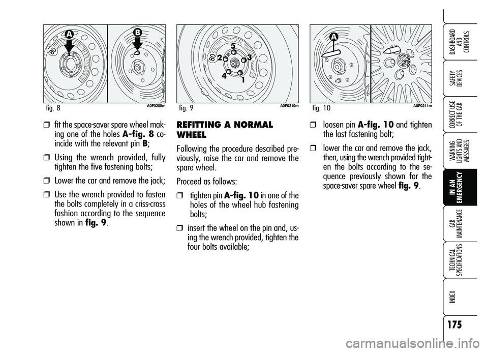
OF THE CAR❒fit the space-saver spare wheel mak-
ing one of the holes A-fig. 8co-
incide with the relevant pin B;
❒Using the wrench provided, fully
tighten the five fastening bolts;
❒Lower the car and remove the jack;
❒Use the wrench provided to fasten
the bolts completely in a criss-cross
fashion according to the sequence
shown in fig. 9.
REFITTING A NORMAL
WHEEL
Following the procedure described pre-
viously, raise the car and remove the
spare wheel.
Proceed as follows:
❒tighten pin A-fig. 10in one of the
holes of the wheel hub fastening
bolts;
❒insert the wheel on the pin and, us-
ing the wrench provided, tighten the
four bolts available;
A0F0210mfig. 9A0F0209mfig. 8A0F0211mfig. 10
❒loosen pin A-fig. 10and tighten
the last fastening bolt;
❒lower the car and remove the jack,
then, using the wrench provided tight-
en the bolts according to the se-
quence previously shown for the
space-saver spare wheel fig. 9.
Page 206 of 271
204
SAFETY
DEVICES
WARNING
LIGHTS AND
MESSAGES
IN AN
EMERGENCY CAR
MAINTENANCE
TECHNICAL
SPECIFICATIONS
INDEX
DASHBOARD
AND
CONTROLS
CORRECT USE
OF THE CAR
IF THE BATTERY
IS FLAT
IMPORTANTThe description of the
battery charging procedure is described
only for informative purposes. This op-
eration should be carried out by Alfa
Romeo Authorized Services.
Charging should be slow at a low amp
rating for 24 hours. Charging for a
longer time may damage the battery.Charge the battery as follows:
❒disconnect battery negative terminal
(–);
❒connect the charger cables to the
battery terminals, observing the
poles;
❒turn on the charger;
❒when you have finished, turn the
charger off before disconnecting the
battery;
❒reconnect battery negative terminal
(–).
The liquid in the battery
is poisonous and corro-
sive. Do not let it touch the
skin or eyes. Recharging the
battery should be done in a
well ventilated area away
from naked flames or possible
sources of sparks: explosion
and fire risk.
WARNING
Do not attempt to
recharge a frozen bat-
tery. Thaw it first, otherwise
it could explode. If the battery
froze, make sure the internal
elements are not broken and
that the casing is not cracked:
risk of spilling the poisonous
and corrosive fluid.
WARNING