lock Alfa Romeo Brera/Spider 2008 Owner handbook (in English)
[x] Cancel search | Manufacturer: ALFA ROMEO, Model Year: 2008, Model line: Brera/Spider, Model: Alfa Romeo Brera/Spider 2008Pages: 270, PDF Size: 3.93 MB
Page 140 of 270

139
SAFETY
DEVICES
WARNING
LIGHTS AND
MESSAGES
IN AN
EMERGENCY
CAR
MAINTENANCE
TECHNICAL
SPECIFICATIONS
INDEX
DASHBOARD
AND
CONTROLS
CORRECT USE
OF THE CAR
STARTING PROCEDURE FOR
PETROL VERSIONS
Proceed as follows:
❒pull up the handbrake;
❒put the gear lever neutral;
❒fit the electronic key into the ignition
device to stop limit;
❒press the clutch (or brake) pedal
down to the floor without pressing the
accelerator;
❒press button START/STOP and re-
lease it as soon as the engine starts.
STARTING PROCEDURE FOR
DIESEL VERSIONS
Proceed as follows:
❒pull up the handbrake;
❒put the gear lever neutral;
❒fit the electronic key into the ignition
device to stop limit. The warning
light
mon the instrument panel
will turn on;
❒wait for the warning light mto turn
off. The hotter the engine is, the quick-
er this will happen;
❒press the clutch (or brake) down to
the floor without pressing the accel-
erator;
❒press button START/STOPas soon
as warning light
mgoes out. If you
wait too long you will lose the bene-
fit of the work done by the glow plugs.
Release the button as soon as the en-
gine starts.WARNINGS
If at start-up the engine turns off, restart
it by pressing the clutch or brake pedal
and then press button START/STOP.
If after a few attempts the engine does
not start, do not insist but contact Alfa
Romeo Authorized Services.
With car started the electronic key is
locked into the ignition device and it can
be removed only after switching the en-
gine off. With car running and key locked
into the ignition device, forced key re-
moval could damage the ignition device.
Page 143 of 270

142
SAFETY
DEVICES
WARNING
LIGHTS AND
MESSAGES
IN AN
EMERGENCY
CAR
MAINTENANCE
TECHNICAL
SPECIFICATIONS
INDEX
DASHBOARD
AND
CONTROLS
CORRECT USE
OF THE CAR
❒fit the metal insert B-fig. 1of the
electronic key into the slot A;
❒remove the electronic key from the
ignition device.
IMPORTANTOnly fit the metal insert
B-fig.1of the electronic key into slot A.
REMOVING THE
ELECTRONIC KEY FROM THE
IGNITION DEVICE IN AN
EMERGENCY
In the event of a failure at engine switch-
ing off system or at electronic key un-
locking system proceed as follows:
❒press the unlocking button to remove
the metal insert (see paragraph
“Electronic key” in section “Dash-
board and controls”);
A0F0043mfig. 1
IMPORTANTIf emergency removal
is carried out with the engine running,
the engine and the instrument panel will
be turned off and the steering lock will
not be engaged; always stop the car be-
fore emergency removal.
Page 144 of 270

143
SAFETY
DEVICES
WARNING
LIGHTS AND
MESSAGES
IN AN
EMERGENCY
CAR
MAINTENANCE
TECHNICAL
SPECIFICATIONS
INDEX
DASHBOARD
AND
CONTROLS
CORRECT USE
OF THE CAR
To release the handbrake proceed as fol-
lows:
❒Slightly lift the handbrake Aand
press release button B;
❒Keep button Bpressed and lower
the lever. Warning light
xon the
instrument panel will turn off.
Press the brake pedal when carrying out
this operation to prevent the car from
moving accidentally.
HANDBRAKE
The handbrake lever A-fig. 2 is locat-
ed between the two front seats. Pull the
handbrake lever Aupwards, until the
car cannot be moved.
With electronic key fitted into the igni-
tion device, the instrument panel warn-
ing light
xwill come on.
IMPORTANT The car shall stop after
a few clicks of the handbrake lever. If
this is not the case, contact Alfa Romeo
Authorized Services to have the hand-
brake adjusted.
A0F0030mfig. 2
PARKING THE CAR
Proceed as follows:
❒Stop the engine and engage the
handbrake;
❒Engage a gear (on a slope, engage
first gear if the car is faced uphill or
reverse if it is faced downhill) and
leave the wheels steered.
Block the wheels with a wedge or a stone
if the car is parked on a steep slope. Do
not leave the electronic key in the igni-
tion switch to prevent draining the bat-
tery.
Never leave children un-
attended in the car. Al-
ways remove the electronic key
when leaving the car and take
it out with you.
WARNING
Page 154 of 270
153
SAFETY
DEVICES
WARNING
LIGHTS AND
MESSAGES
IN AN
EMERGENCY
CAR
MAINTENANCE
TECHNICAL
SPECIFICATIONS
INDEX
DASHBOARD
AND
CONTROLS
CORRECT USE
OF THE CAR
W W
A A
R R
N N
I I
N N
G G
L L
I I
G G
H H
T T
S S
A A
N N
D D
M M
E E
S S
S S
A A
G G
E E
S S
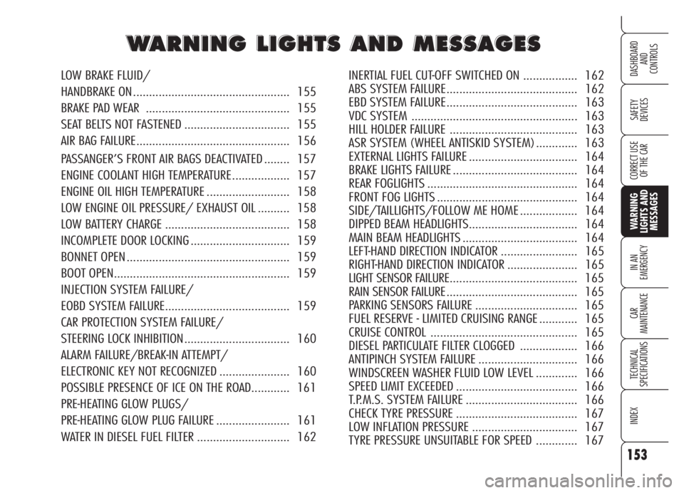
LOW BRAKE FLUID/
HANDBRAKE ON ................................................. 155
BRAKE PAD WEAR ............................................. 155
SEAT BELTS NOT FASTENED ................................. 155
AIR BAG FAILURE................................................ 156
PASSANGER’S FRONT AIR BAGS DEACTIVATED ........ 157
ENGINE COOLANT HIGH TEMPERATURE.................. 157
ENGINE OIL HIGH TEMPERATURE .......................... 158
LOW ENGINE OIL PRESSURE/ EXHAUST OIL .......... 158
LOW BATTERY CHARGE ....................................... 158
INCOMPLETE DOOR LOCKING ............................... 159
BONNET OPEN ................................................... 159
BOOT OPEN....................................................... 159
INJECTION SYSTEM FAILURE/
EOBD SYSTEM FAILURE....................................... 159
CAR PROTECTION SYSTEM FAILURE/
STEERING LOCK INHIBITION................................. 160
ALARM FAILURE/BREAK-IN ATTEMPT/
ELECTRONIC KEY NOT RECOGNIZED ...................... 160
POSSIBLE PRESENCE OF ICE ON THE ROAD............ 161
PRE-HEATING GLOW PLUGS/
PRE-HEATING GLOW PLUG FAILURE ....................... 161
WATER IN DIESEL FUEL FILTER ............................. 162INERTIAL FUEL CUT-OFF SWITCHED ON ................. 162
ABS SYSTEM FAILURE......................................... 162
EBD SYSTEM FAILURE......................................... 163
VDC SYSTEM .................................................... 163
HILL HOLDER FAILURE ........................................ 163
ASR SYSTEM (WHEEL ANTISKID SYSTEM) ............. 163
EXTERNAL LIGHTS FAILURE .................................. 164
BRAKE LIGHTS FAILURE ....................................... 164
REAR FOGLIGHTS ............................................... 164
FRONT FOG LIGHTS ............................................ 164
SIDE/TAILLIGHTS/FOLLOW ME HOME .................. 164
DIPPED BEAM HEADLIGHTS.................................. 164
MAIN BEAM HEADLIGHTS .................................... 164
LEFT-HAND DIRECTION INDICATOR ........................ 165
RIGHT-HAND DIRECTION INDICATOR ...................... 165
LIGHT SENSOR FAILURE........................................ 165
RAIN SENSOR FAILURE......................................... 165
PARKING SENSORS FAILURE ................................ 165
FUEL RESERVE - LIMITED CRUISING RANGE ............ 165
CRUISE CONTROL .............................................. 165
DIESEL PARTICULATE FILTER CLOGGED .................. 166
ANTIPINCH SYSTEM FAILURE ............................... 166
WINDSCREEN WASHER FLUID LOW LEVEL ............. 166
SPEED LIMIT EXCEEDED ...................................... 166
T.P.M.S. SYSTEM FAILURE ................................... 166
CHECK TYRE PRESSURE ...................................... 167
LOW INFLATION PRESSURE ................................. 167
TYRE PRESSURE UNSUITABLE FOR SPEED ............. 167
Page 160 of 270

BOOT OPEN
SymbolR(red) + mes
sage on the display indicate
that the boot is open.
BONNET OPEN
(where provided)
SymbolS(red) + mes-
sage on the display indicate that the
bonnet is open.
159
SAFETY
DEVICES
WARNING
LIGHTS AND
MESSAGES
IN AN
EMERGENCY
CAR
MAINTENANCE
TECHNICAL
SPECIFICATIONS
INDEX
DASHBOARD
AND
CONTROLS
CORRECT USE
OF THE CAR
INJECTION SYSTEM
FAILURE (diesel
versions - amber)
EOBD SYSTEM
FAILURE
(petrol versions -
amber)
(optional for
versions/ markets
where applicable)
Injection system failure
Fitting the key into the ignition device
the warning light turns on, but it should
go off when the engine has started.
The warning light stays on or it turns on
when travelling to indicate a malfunc-
tion in the injection/exhaust system
with possible lack of performance, poor
driveability and high consumption.
In these conditions it is possible to con-
tinue driving without however requiring
heavy effort or high speed from the en-
gine. In any case, contact Alfa Romeo
Authorized Services as soon as possible.EOBD system failure
(optional for versions/
markets where applicable)
Under normal conditions, fitting the elec-
tronic key into the ignition device, the
warning light turns on, but it should go
off when the engine has started. This in-
dicates proper operation of the warn-
ing light.
If the warning light stays on or turns on
when travelling:
– glowing steadily (together with
the message on the display): means a
fault in the supply/ignition system
which could cause high emissions at the
exhaust, possible lack of performance,
poor handling and high consumption lev-
els. In these conditions it is possible to
continue driving without however re-
quiring heavy effort or high speed from
the engine. Prolonged use of the car
with the warning light on may cause
damages. Contact Alfa Romeo Autho-
rized Services as soon as possible.
The warning light goes off if the fault
disappears, but it is however stored by
the system.
INCOMPLETE DOOR
LOCKING (red)
Symbol´+ message on the
display indicate that one of the doors
is not closed.
U´
S
R
Page 161 of 270

CAR PROTECTION
SYSTEM FAILURE
(amber)
STEERING LOCK
INHIBITION (amber)
Car protection system failure
The message on the display indicates
car protection system failure: in this
event contact Alfa Romeo Authorized
Services as soon as possible.
Steering lock inhibition
The display will show a dedicated mes-
sage when the engine is killed by re-
moving the electronic key from the ig-
nition device while the car is moving.
ALARM FAILURE
(where provided)
(amber)
BREAK-IN ATTEMPT
(amber)
ELECTRONIC KEY
NOT RECOGNIZED
(amber)
Alarm failure
The message + symbol on the display
indicate a failure in the alarm system.
Contact Alfa Romeo Authorized Services
as soon as possible.
Break-in attempt
The message + symbol on the display
indicate an attempt of break-in. Contact
Alfa Romeo Authorized Services as soon
as possible.
Electronic key not recognized
The message + symbol on the display in-
dicate that the electronic key being used
for start-up is not enabled. – flashing: indicates the possibility of
damage to the catalyst (see “EOBD sys-
tem” in section “Dashboard and con-
trols”). If the light flashes, it is neces-
sary to release the accelerator pedal to
lower the speed of the engine until the
warning light stops flashing; continue
the journey at moderate speed, trying
to avoid driving conditions that may
cause further flashing and contact Alfa
Romeo Authorized Services as soon as
possible.
160
SAFETY
DEVICES
WARNING
LIGHTS AND
MESSAGES
IN AN
EMERGENCY
CAR
MAINTENANCE
TECHNICAL
SPECIFICATIONS
INDEX
DASHBOARD
AND
CONTROLS
CORRECT USE
OF THE CAR
If when fitting the key in-
to the ignition device, the
warning light
Udoes
not turn on or if turns on with
fixed light or flashing when the
car is travelling, contact Alfa
Romeo Authorized Services as
soon as possible. Warning light
Uoperation can by checked by
traffic agents by proper equip-
ment therefore, comply with
laws and regulations in force in
the country where you are dri-
ving.
>Y
Page 164 of 270

163
SAFETY
DEVICES
WARNING
LIGHTS AND
MESSAGES
IN AN
EMERGENCY
CAR
MAINTENANCE
TECHNICAL
SPECIFICATIONS
INDEX
DASHBOARD
AND
CONTROLS
CORRECT USE
OF THE CAR
EBD SYSTEM
FAILURE (red)
(amber)
With the engine running the
turning on at the same time
of warning lights
>andx
(together with the message on the dis-
play) indicates that the EBD system is
inefficient; in this case heavy braking
may cause the rear wheels to lock be-
fore time, with the possibility of skid-
ding.
Drive with the utmost care to the near-
est Alfa Romeo Authorized Service to
have the system checked.
VDC SYSTEM
(where provided)
(amber)
Fitting the key into the ignition device
the warning light turns on, but it should
go off after few seconds.
The warning light flashes when the VDC
cuts in, to alert the driver that the sys-
tem is adapting to the road surface grip
conditions.
VDC deactivation
When the VDC is deactivated manually
(pressing the ASR/VDC button for 2 sec-
onds) (see paragraph “VDC system” in
section “Dashboard and controls”) the
display will show the dedicated mes-
sage.
VDC system failure
In the event of a failure the VDC system
is deactivated automatically and warn-
ing light
áturns on glowing steadily
(together with a message on the dis-
play). In this case contact Alfa Romeo
Authorized Services as soon as possible.
>
xá
ASR SYSTEM
(WHEEL ANTISKID
SYSTEM)
(amber)
Fitting the key into the ignition device
the warning light turns on, but it should
go off after few seconds. The warning
light flashes when the system cuts in, to
alert the driver that the system is adapt-
ing to the road surface grip conditions.
ASR deactivation
When the ASR is deactivated manually
(pressing the ASR/VDC button) (see
paragraph “ASR system” in section
“Dashboard and controls”) the led on
the ASR/VDC button will turn on and
the display will show symbol
V.
á
HILL HOLDER
FAILURE
(amber)
In the event of a failure to the Hill Hold-
er system, the display will show a mes-
sage + symbol. In this case contact Al-
fa Romeo Authorized Services.
*
Page 182 of 270
181
SAFETY
DEVICES
WARNING
LIGHTS AND
MESSAGES
IN AN
EMERGENCY
CAR
MAINTENANCE
TECHNICAL
SPECIFICATIONS
INDEX
DASHBOARD
AND
CONTROLS
CORRECT USE
OF THE CAR
A0F0215mfig. 18A0F0216mfig. 19
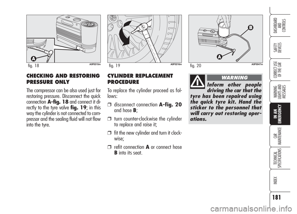
CHECKING AND RESTORING
PRESSURE ONLY
The compressor can be also used just for
restoring pressure. Disconnect the quick
connectionA-fig. 18and connect it di-
rectly to the tyre valve fig. 19; in this
way the cylinder is not connected to com-
pressor and the sealing fluid will not flow
into the tyre.
A0F0047mfig. 20
Inform other people
driving the car that the
tyre has been repaired using
the quick tyre kit. Hand the
sticker to the personnel that
will carry out restoring oper-
ations.
WARNINGCYLINDER REPLACEMENT
PROCEDURE
To replace the cylinder proceed as fol-
lows:
❒disconnect connection A-fig. 20
and hose B;
❒turn counter-clockwise the cylinder
to replace and raise it;
❒fit the new cylinder and turn it clock-
wise;
❒refit connection Aor connect hose
Binto its seat.
Page 184 of 270
183
SAFETY
DEVICES
WARNING
LIGHTS AND
MESSAGES
IN AN
EMERGENCY
CAR
MAINTENANCE
TECHNICAL
SPECIFICATIONS
INDEX
DASHBOARD
AND
CONTROLS
CORRECT USE
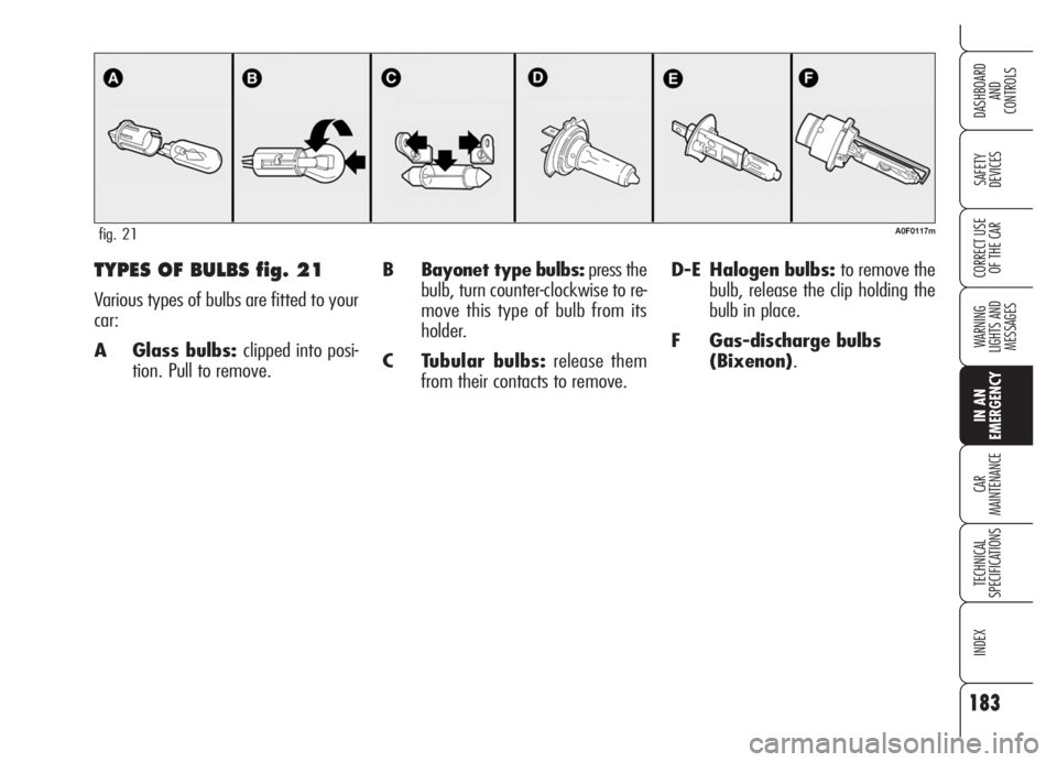
OF THE CARB Bayonet type bulbs:press the
bulb, turn counter-clockwise to re-
move this type of bulb from its
holder.
C Tubular bulbs:release them
from their contacts to remove.D-E Halogen bulbs: to remove the
bulb, release the clip holding the
bulb in place.
F Gas-discharge bulbs
(Bixenon).TYPES OF BULBS fig. 21
Various types of bulbs are fitted to your
car:
A Glass bulbs: clipped into posi-
tion. Pull to remove.
A0F0117mfig. 21
Page 186 of 270
185
SAFETY
DEVICES
WARNING
LIGHTS AND
MESSAGES
IN AN
EMERGENCY
CAR
MAINTENANCE
TECHNICAL
SPECIFICATIONS
INDEX
DASHBOARD
AND
CONTROLS
CORRECT USE
OF THE CAR
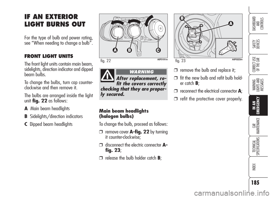
Main beam headlights
(halogen bulbs)
To change the bulb, proceed as follows:
❒remove cover A-fig. 22by turning
it counter-clockwise;
❒disconnect the electric connectorA-
fig. 23;
❒release the bulb holder catch B;
IF AN EXTERIOR
LIGHT BURNS OUT
For the type of bulb and power rating,
see “When needing to change a bulb”.
FRONT LIGHT UNITS
The front light units contain main beam,
sidelights, direction indicator and dipped
beam bulbs.
To change the bulbs, turn cap counter-
clockwise and then remove it.
The bulbs are arranged inside the light
unitfig. 22as follows:
AMain beam headlights
BSidelights/direction indicators
CDipped beam headlights
A0F0191mfig. 22
After replacement, re-
fit the covers correctly
checking that they are proper-
ly secured.
WARNING
A0F0223mfig. 23
❒remove the bulb and replace it;
❒fit the new bulb and refit bulb hold-
er catch B;
❒reconnect the electrical connector A;
❒refit the protective cover properly.