brake sensor Alfa Romeo Giulia 2017 Owner's Manual
[x] Cancel search | Manufacturer: ALFA ROMEO, Model Year: 2017, Model line: Giulia, Model: Alfa Romeo Giulia 2017Pages: 268, PDF Size: 18.64 MB
Page 99 of 268

and environmental conditions are such
that they wouldn't cause the tires to
slip. When the road and environmental
conditions require better traction, the
vehicle automatically goes to AWD
mode.
The driving mode, RWD or AWD, is
shown on the instrument cluster
display.
Note:If the system failure symbol
switches on, after starting the engine or
while driving, it means that the AWD
system is not working properly. If the
warning message activates frequently, it
is recommended to carry out the
maintenance operations.
Electronic Stability
Control (ESC) System
The ESC system improves the
directional control and stability of the
car in various driving conditions.
The ESC system corrects the car’s
understeer and oversteer, distributing
the brake force on the appropriate
wheels. The torque supplied by the
engine can also be reduced in order to
maintain control of the vehicle.
The ESC system uses sensors installed
on the car to determine the path that
the driver intends to follow and
compares it with the car’s effective
path. When the real path deviates from
the desired path, the ESC system
intervenes to counter the vehicle’s
understeer or oversteer.
Oversteer occurs when the car is
turning more than it should according
to the angle of the steering wheel.
Understeer occurs when the vehicle
is turning less than it should according
to the angle of the steering wheel.
System Intervention
The intervention of the system is
indicated by the flashing of the ESC
warning light on the instrument panel,
to inform the driver that the vehicle
stability and grip are critical.
Warning!
Electronic Stability Control (ESC) cannot
prevent the natural laws of physics from
acting on the vehicle, nor can it increase
the traction afforded by prevailing road
conditions. ESC cannot prevent accidents,
including those resulting from excessive
speed in turns, driving on very slippery
surfaces, or hydroplaning. ESC also cannot
prevent accidents resulting from loss of
vehicle control due to inappropriate driver
input for the conditions. Only a safe,
attentive, and skillful driver can prevent
accidents. The capabilities of an ESC
equipped vehicle must never be exploited
in a reckless or dangerous manner which
could jeopardize the user’s safety or the
safety of others.
Vehicle modifications, or failure to
properly maintain your vehicle, may change
the handling characteristics of your vehicle,
and may negatively affect the performance
of the ESC system. Changes to the
steering system, suspension, braking
system, tire type and size or wheel size
may adversely affect ESC performance.
Improperly inflated and unevenly worn tires
may also degrade ESC performance. Any
vehicle modification or poor vehicle
maintenance that reduces the effectiveness
of the ESC system can increase the risk of
loss of vehicle control, vehicle rollover,
personal injury and death.
Traction Control System
(TCS)
The system automatically operates in
the event of slipping, loss of grip on wet
roads (hydroplaning), and acceleration
on one or both drive wheels on roads
that are slippery, snowy, icy, etc.
Depending on the slipping conditions,
two different control systems are
activated:
If the slipping involves both drive
wheels, the system intervenes, reducing
the power transmitted by the engine.
If the slipping only involves one of the
drive wheels, the Brake Limited
Differential (BLD) function is activated,
automatically braking the wheel which
is slipping (the behavior of a self-locking
differential is simulated). This will
increase the engine torque transferred
to the wheel which isn't slipping.
97
Page 101 of 268
Dynamic Steering
Torque (DST) System
The DST function uses the integration
of the ESC system with the electric
power steering to increase the safety
level of the whole vehicle.
In critical situations (braking on surfaces
with different grip conditions), the ESC
system controls the steering through
the DST function to implement an
additional torque contribution on the
steering wheel in order to suggest the
most correct maneuver to the driver.
The coordinated action of the brakes
and steering increases the sensation of
safety and control of the vehicle.
Note:
The DST feature is only meant to help
the driver realize the correct course of
action through small torques on the
steering wheel, which means the
effectiveness of the DST feature is
highly dependent on the drivers
sensitivity and overall reaction to the
applied torque. It is very important to
realize that this feature will not steer the
vehicle, meaning the driver is still
responsible for steering the vehicle.
Active Torque Vectoring
(ATV) System
The dynamic drive control is used to
optimize and balance the drive torque
between the wheels of the same axles.
The ATV system improves the grip in
turns, sending more drive torque to the
external wheel.
Given that, in a turn, the external
wheels of the car travel more than the
internal ones and therefore turn faster,
sending a higher thrust to the external
rear wheel allows for the car to be more
stable and to not suffer an "understeer"
condition. Understeer occurs when the
vehicle is turning less than appropriate
for the steering wheel position.
AUXILIARY DRIVING
SYSTEMS
The vehicle can feature the following
auxiliary driving systems:
Blind Spot Monitoring (BSM)
Forward Collision Warning (FCW)
Tire Pressure Monitoring System
(TPMS)
For the operation of the systems, see
the following pages.
Blind Spot Monitoring
(BSM) System
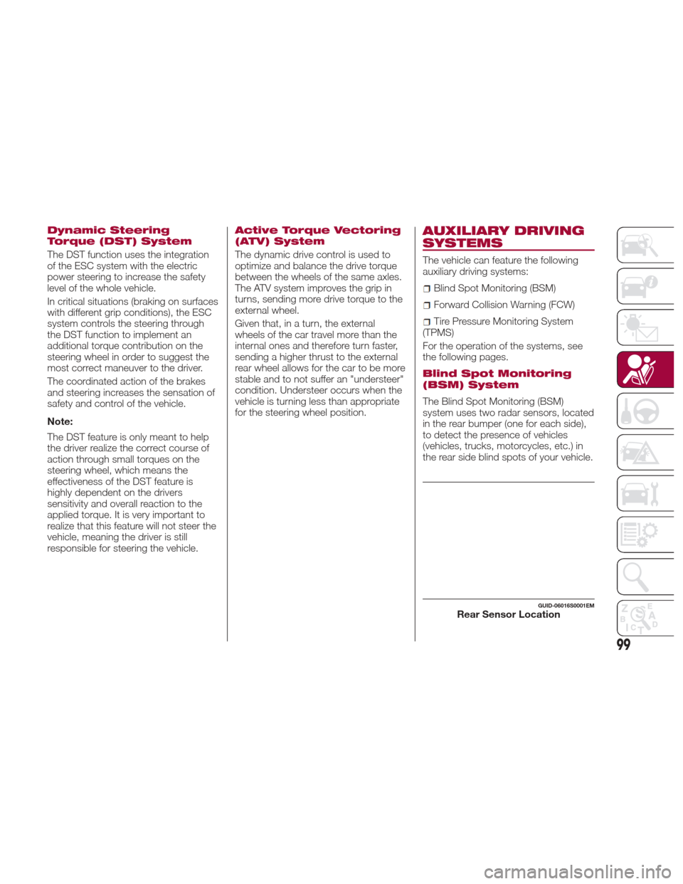
The Blind Spot Monitoring (BSM)
system uses two radar sensors, located
in the rear bumper (one for each side),
to detect the presence of vehicles
(vehicles, trucks, motorcycles, etc.) in
the rear side blind spots of your vehicle.
GUID-06016S0001EMRear Sensor Location
99
Page 106 of 268

In this case, it is still possible to drive
the vehicle, but you are advised to
contact an authorized dealer as soon
as possible.
Radar Indication Not Available
If conditions are such that the radar
cannot detect obstacles correctly, the
system is deactivated and a dedicated
message appears on the display. This
generally occurs in the event of poor
visibility, such as when it is snowing or
raining heavily.
The system can also be temporarily
dimmed due to obstructions such as
mud, dirt or ice on the bumper. In such
cases, a dedicated message will be
shown on the display and the system
will be deactivated. This message can
sometimes appear in conditions of high
reflectivity (e.g. tunnels with reflective
tiles or ice or snow). When the
conditions limiting the system functions
end, this will go back to normal and
complete operation.
In certain particular cases, this
dedicated message could be displayed
when the radar is not detecting any
vehicles or objects within its view range.
If atmospheric conditions are not the
real reason behind this message, check
if the sensor is dirty. It could be
necessary to clean or remove any
obstructions in the area.
If the message appears often, even in
the absence of atmospheric conditions
such as snow, rain, mud or otherobstructions, contact an authorized
dealer for a sensor alignment check.
In the absence of visible obstructions,
manually removing the decorative cover
trim and cleaning the radar surface
could be required. Have this operation
performed at an authorized dealer.
Note:
It is recommended that you do
not install devices, accessories or
aerodynamic attachments in front of the
sensor or darken it in any way, as this
can compromise the correct functioning
of the system.
Frontal Collision Alarm With Active
Braking — If Equipped
If this function is selected, the brakes
are operated to reduce the speed of the
vehicle in the event of potential frontal
impact.
This function applies an additional
braking pressure if the braking pressure
applied by the driver does not suffice to
prevent potential frontal impact.
The function is active with speed above
4 mph (7 km/h).
Driving In Special Conditions
In certain driving conditions, such as,
for example:
Driving close to a bend.
The vehicle ahead is leaving a
roundabout.
Vehicles with small dimensions
and/or not aligned in the driving lane.
Lane change by other vehicles.
Vehicles travelling at right angles to
the vehicle.
System intervention might be
unexpected or delayed. The driver must
therefore be very careful, keeping
control of the vehicle to drive in
complete safety.
Note: In particularly complex traffic
conditions, the driver can deactivate the
system manually through the Connect
system.
Driving Close To A Bend
When entering or leaving a wide bend,
the system may detect a vehicle in front
you, but not driving on the same driving
lane. In cases such as these, the
system may intervene.
06016S0005EMDriving Around Wide Curves
104
SAFETY
Page 158 of 268

ADAPTIVE CRUISE
CONTROL (ACC) —
IF EQUIPPED
System Description
The Adaptive Cruise Control (ACC) is a
driver assist system that combines the
speed control functions for controlling
the distance from the vehicle ahead.
The system allows to set and hold the
vehicle at the desired speed without
needing to press the accelerator. It also
allows to set and hold a distance from
the vehicle ahead (these settings are set
by the driver).
The Adaptive Cruise Control (ACC) uses
a radar sensor located behind the front
bumper and a camera located in the
center/upper part of the windshield, to
detect the presence of a vehicle close
ahead.This system enhances driving comfort
while on the highway or out of town
with light traffic.
Warning!
Adaptive Cruise Control (ACC) is a
convenience system. It is not a substitute
for active driving involvement. It is always
the driver’s responsibility to be attentive of
road, traffic, and weather conditions,
vehicle speed, distance to the vehicle
ahead; and, most importantly, brake
operation to ensure safe operation of the
vehicle under all road conditions. Your
complete attention is always required while
driving to maintain safe control of your
vehicle. Failure to follow these warnings
can result in a collision and death or
serious personal injury.
The ACC system:
Does not react to pedestrians,
oncoming vehicles, and stationary objects
(e.g., a stopped vehicle in a traffic jam or a
disabled vehicle).
Cannot take street, traffic, and weather
conditions into account, and may be
limited upon adverse sight distance
conditions.
Does not always fully recognize complex
driving conditions, which can result in
wrong or missing distance warnings.
Will bring the vehicle to a complete stop
while following a target vehicle and hold the
vehicle for approximately 3 minutes in the
stop position. If the target vehicle does not
start moving within 3 minutes the parking
brake will be activated, and the ACC
system will be canceled.
You should switch off the ACC system:
When driving in fog, heavy rain, heavy
snow, sleet, heavy traffic, and complex
driving situations (i.e., in highway
construction zones).
When entering a turn lane or highway off
ramp; when driving on roads that are
winding, icy, snow-covered, slippery, or
have steep uphill or downhill slopes.
When circumstances do not allow safe
driving at a constant speed.
GUID-06016S0003EMFront Bumper Radar Location
06016S0004EMWindshield Camera Location
156
STARTING AND OPERATING
Page 160 of 268

While the accelerator pedal is pressed,
the system will not be able to control
the distance between the vehicle and
the one ahead. In this case, the speed
will be determined only by the position
of the accelerator pedal.
The system will return to normal
operation as soon as the accelerator
pedal is released.
The systemcannotbe set:
When pressing the brake pedal.
When the brakes are overheated.
When the electric park brake has
been operated.
When either P (PARK), R (REVERSE)
or N (NEUTRAL) is engaged.
When the engine rpm is above a
maximum threshold.
When the vehicle speed is not within
the operational speed range.
When the ESC (or ABS or other
stability control systems) are operating
or have just operated.
When the ESC system is off.
When the Forward Collision Warning
Plus system (if equipped) is braking
automatically.
In the event of system failure.
When the engine is off.
In case of obstruction of the radar
sensor (in this case the bumper area
where it is located must be cleaned).
If the system is set, the conditions
described above also cause a
cancellation or deactivation of the
system. These situations may vary
according to the conditions.
Note:
The system will not be deactivated
when speeds higher than those set are
reached by pressing the accelerator
pedal above 110 mph (180 km/h). In
these situations, the system may not
work correctly and it is recommended
to deactivate it.
Changing Speed
Increasing speed
Once the system has been activated,
you can increase the speed by lifting
the SET switch. Each time it is
operated, the speed increases by
1 mph.
By holding the button up, the set speed
will increase in increments of five mph
until the button is released. Then, the
new speed will be set.
Decreasing speed
Once the system has been activated,
you can decrease the speed by
lowering the SET switch. Each time it is
operated, the speed decreases by
1 mph. By holding the button down, the set
speed will decrease in increments of
five mph until the button is released.
Then, the new speed will be set.
Note:
Moving the SET switch allows you
to adjust the speed according to the
selected unit of measurement ("US" or
"metric") set on the Connect system
(see dedicated supplement).
When the unit of measurement is
set to metric, holding the SET switch
the speed will change in 10 km/h
increments.
By keeping the accelerator pedal
depressed, the vehicle can continue to
accelerate beyond the set speed. In this
case, use the SET switch to set the
speed to the vehicle’s current speed.
When you push the SET button to
reduce the speed, the braking system
intervenes automatically if the engine
brake does not slow the vehicle down
sufficiently to reach the set speed. The
device holds the set speed uphill and
downhill; however a slight variation is
entirely normal, particularly on slight
inclines.
The transmission could change to a
lower gear when driving downhill, or
when accelerating. This is normal and
necessary to maintain the set speed.
The system will disable while driving
if the brakes overheat.
158
STARTING AND OPERATING
Page 162 of 268

The setting is 4 (maximum) the first time
the system is used. After the distance
has been modified by the driver, the
new distance will be stored also after
the system is deactivated and
reactivated.
To Decrease The Distance
Push and release the distance button to
decrease the distance setting. The
distance setting decreases by one bar
(shorter) every time the button is
pushed.
The set speed is held if there are no
vehicles ahead. Once the shortest
distance has been selected, the next
push of the button will set the
maximum distance.
If a slower vehicle is detected in the
same lane, the vehicle icon on the
display illuminates from grey to white.
The system automatically adjusts thevehicle’s speed to keep the set
distance, independently of the set
speed.
The vehicle holds the set distance until:
The vehicle ahead accelerates to a
speed higher than the set speed.
The vehicle ahead leaves the lane or
the detection field of the Adaptive
Cruise Control system sensor.
The distance setting is changed.
The Adaptive Cruise Control system
is deactivated/paused.
Warning!
The maximum breaking applied by the
system is limited. The driver may apply the
brakes in all cases if needed.
If the system predicts that the braking
level is insufficient to hold the set distance,
either “BRAKE!” or a dedicated message is
displayed to warn the driver of approaching
the vehicle ahead. An acoustic signal is
also emitted. In this case, it is advised to
brake immediately as necessary to hold a
safe distance from the vehicle ahead.
The driver is responsible for ensuring
that there are no pedestrians, other
vehicles or objectives along the direction of
the vehicle. Failure to comply with these
precautions may cause serious accidents
and injuries.
The driver is fully responsible for holding
a safe distance from the vehicle ahead
respecting the highway code in force in the
respective country.
“Stop And Go” Function
The “Stop and Go” operating strategy
allows you to maintain a safe distance
from the vehicle ahead until the vehicle
has completely stopped. It will also
restart the vehicle automatically if the
vehicle ahead drives away within two
seconds, otherwise it is necessary to
press the accelerator pedal or push the
RES button to restart.
Warning!
When the ACC system is resumed, the
driver must ensure that there are no
pedestrians, vehicles or objects in the path
of the vehicle. Failure to follow these
warnings can result in a collision and death
or serious personal injury.
GUID-07146S0015EMDistance Button
160
STARTING AND OPERATING
Page 163 of 268
Deactivation
The system is deactivated and the set
speed is canceled if:
Thebutton on the Active Cruise
Control is pushed (with the system
enabled or paused).
The ignition is in STOP mode.
RACE mode is activated.
The system is canceled (the set speed
and distance are stored):
When the system is paused (Refer to
the “Activation / Deactivation” section).
When the conditions shown in the
“Setting The Desired Speed” section
occur.
Limited Operation
Warning
If the dedicated message is shown on
the display, a condition limiting the
Adaptive Cruise Control operation may
have occurred.
This could be due to an obstruction of
the vehicles sensor or camera. It could
also be due to a fault in the system. If
an obstruction is detected, clean the
area of the windshield opposite the
interior rear view mirror, where the
camera is located, as well as the area
of the front bumper where the sensor is
located. Then check that the message
has disappeared. When the conditions limiting the system
functions end, normal operation will
resume.
Should the fault persist, contact an
authorized dealer.
Precautions While
Driving
The system may not work correctly in
some driving conditions (see below):
the driver must control the vehicle at all
times.
Vehicle Not Aligned
The system may not detect a vehicle
travelling in the same lane, in the same
direction, but is not aligned. It also may
not detect a vehicle which is cutting in
from a side lane. Sufficient distance
from the vehicles ahead may not be
guaranteed in these cases.
The non-aligned vehicle can weave in
and out of the driving lane causing the
vehicle to brake or accelerate
unexpectedly.
Steering And Curves
Driving on curves with the system set
could limit speed and acceleration to
guarantee vehicle stability, even if no
vehicles are detected ahead.
When leaving the curve, the system
resets the previously set speed.
Note:
In cases of narrow curves, the
performance of the system could be
limited. In this case, it is advisable to
deactivate the system.
Using The System On Slopes
When driving on roads with a variable
incline, the system may not detect the
presence of a vehicle in the lane.
System performance could be limited
according to speed, load, traffic
conditions and steep slopes.
Lane Change
The system may not detect the
presence of a vehicle until it is fully in
your lane.
GUID-07146S0011EMSteering And Curves
161
Page 166 of 268
If the obstacle is detected in the rear left
and/or right area, a single flashing arc
will be shown in the corresponding area
on the display and the system will emit
an acoustic signal, either at frequent
intervals or constantly.
In general, the vehicle is closer to the
obstacle when a single flashing arc is
shown on the display and the acoustic
signal becomes continuous.
If several obstacles are detected
simultaneously in the rear area, the
display will show all of them, regardless
of the area in which they were detected.
The color on the display depends on
the distance from and position of the
obstacle.
It is possible to exit from the display
screen by pressing the Rotary Pad,
however, the acoustic alert will remain
active.
Fault Indication
Parking sensor faults, if any, will be
indicated when REVERSE is engaged
by a message on the instrument cluster
display. Refer to "Warning Lights And
Messages" in "Getting To Know Your
Instrument Panel".
Messages On The Display
In case of system failure, a dedicated
message appears on the instrument
cluster for about 5 seconds.Cleaning The Front Sensors:Ifthe
display shows a message requiring the
sensors to be cleaned, make sure that
the outer surface and the underside of
the rear bumper is free of debris (e.g.
snow, mud, ice, etc.). Once these areas
are clear, place the ignition in STOP
mode. Then, return it to ON mode. If
the message is still displayed, contact
an authorized dealer.
Audio System Not Available :Ifthe
display shows a message that the
audio system is not available, it means
that the acoustic signal will be emitted
by the instrument panel, and not
through the vehicles speakers.
Note: Some conditions may influence
the performance of the ParkSense
system:
Reduced sensor sensitivity could
be due to the presence of ice, snow,
mud, or thick paint on the surface of
the sensor.
The sensors may detect a false
obstacle (echo interference) due to
mechanical interference, for example
when washing the vehicle or in
extreme weather.
The signals sent by the sensors can
be altered by the presence of
ultrasonic systems (e.g. pneumatic
brake systems of trucks or pneumatic
drills) near the vehicle.
System performance can be
influenced by the position of the
sensors. For example, due to a change
in the ride setting (caused by wear to
the shock absorbers or suspension),
by changing tires, overloading the
vehicle or operations that require the
vehicle to be lowered.
Be sure not to place bumper
stickers or other adhesives over the
sensors as this will affect system
performance.
Warning!
Drivers must be careful when backing up
even when using the Parking Sensor
system. Always check carefully behind your
vehicle, and be sure to check for
pedestrians, animals, other vehicles,
obstructions, or blind spots before backing
up. You are responsible for the safety of
your surroundings and must continue to
pay attention while backing up. Failure to
do so can result in serious injury or death.
164
STARTING AND OPERATING
Page 168 of 268
Note:If the sensors detect several
front and rear obstacles, the closest
obstacle is considered. An intermittent
signal will sound if the obstacles are at
the same distance (front and rear).
When the system emits an acoustic
signal, the volume of the Connect
system, if activated, is automatically
lowered.
Indication On Display
The driver can select the type of
warning they would like to be displayed
through the Connect system. To access
the function on the main menu, select in
the following order:
1. “Settings”
2. “Driver assistance”
3. “Park Sensors”
4. “Mode”
5. “Sound-Display”
Visual Indications
The system indicates the presence of
an obstacle by displaying a single arc in
the detected areas, in relation to the
distance of the object and the position
of the vehicle.
If the obstacle is detected in the front or
rear central area, a single arc will be
displayed as the obstacle approaches,
first constant, then flashing, in addition
to an acoustic signal. If the obstacle is detected in the front or
rear left and/or right area, a single
flashing arc will be shown in the
corresponding area on the display and
the system will emit an acoustic signal,
either at frequent intervals or constantly.
If several obstacles are detected
simultaneously in the front and rear
area, the display will show all of them,
regardless of the area in which they
were detected.
In general, the vehicle is closer to the
obstacle when a single or several
flashing arcs are shown on the display
and the acoustic signal becomes
continuous. The color on the display
depends on the distance from and
position of the obstacle.
It is possible to exit from the display
screen by pressing the Rotary Pad,
however, the acoustic alert will remain
active.
Fault Indication
Parking sensor faults, if any, will be
indicated by a message on the display
on the instrument cluster. Refer to
"Warning Lights And Messages" in
"Getting To Know Your Instrument
Panel".
Messages On The Display
In case of system failure, a dedicated
message appears on the instrument
cluster for about 5 seconds.Cleaning the front or rear
sensors: If the display shows a
message requiring the sensors to be
cleaned, make sure that the outer
surface and the underside of the front
and rear bumpers are free of debris
(e.g. snow, mud, ice, etc.). Once these
areas are clear, place the ignition in
STOP mode. Then, return it to ON
mode. If the message is still displayed,
contact an authorized dealer.
Audio system not available :Ifthe
display shows a message that the
audio system is not available, it means
that the acoustic signal will be emitted
by the instrument panel, and not
through the vehicles speakers.
Note: Some conditions may influence
the performance of the ParkSense
system:
Reduced sensor sensitivity could
be due to the presence of ice, snow,
mud, or thick paint on the surface of
the sensor.
The sensors may detect a false
obstacle (echo interference) due to
mechanical interference, for example
when washing the vehicle or in
extreme weather.
The signals sent by the sensors can
be altered by the presence of
ultrasonic systems (e.g. pneumatic
brake systems of trucks or pneumatic
drills) near the vehicle.
166
STARTING AND OPERATING
Page 264 of 268
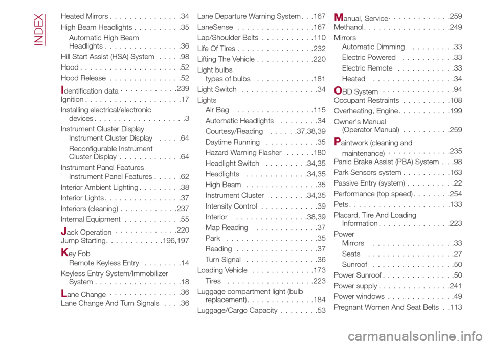
Heated Mirrors...............34
High Beam Headlights ..........35
Automatic High Beam
Headlights ................36
Hill Start Assist (HSA) System .....98
Hood.....................52
Hood Release ...............52
Identification data ............239
Ignition ....................17
Installing electrical/electronic devices ...................3
Instrument Cluster Display Instrument Cluster Display .....64
Reconfigurable Instrument
Cluster Display .............64
Instrument Panel Features Instrument Panel Features ......62
Interior Ambient Lighting .........38
Interior Lights ................37
Interiors (cleaning) ............237
Internal Equipment ............55
Jack Operation.............220
Jump Starting ............196,197
Key Fob
Remote Keyless Entry ........14
Keyless Entry System/Immobilizer System ..................18
Lane Change ...............36
Lane Change And Turn Signals ....36Lane Departure Warning System . . .167
LaneSense
............... .167
Lap/Shoulder Belts ...........110
Life Of Tires ............... .232
Lifting The Vehicle ............220
Light bulbs types of bulbs ............181
Light Switch ................34
Lights AirBag ............... .115
Automatic Headlights ........34
Courtesy/Reading ......37,38,39
Daytime Running ...........35
Hazard Warning Flasher ......180
Headlight Switch .........34,35
Headlights .............34,35
High Beam ...............35
Instrument Cluster ........34,35
Intensity Control ............39
Interior ...............38,39
Map Reading .............37
Park ...................35
Reading .................37
Turn Signal ...............36
Loading Vehicle .............173
Tires ................. .223
Luggage compartment light (bulb replacement) ..............184
Luggage/Cargo Capacity ........53
Manual, Service.............259
Methanol ................. .249
Mirrors Automatic Dimming .........33
Electric Powered ...........33
Electric Remote ............33
Heated .................34
OBD System ...............94
Occupant Restraints ..........108
Overheating, Engine ...........199
Owner's Manual (Operator Manual) ..........259
Paintwork (cleaning and
maintenance) .............235
Panic Brake Assist (PBA) System . . .98
Park Sensors system ..........163
Passive Entry (system) ..........22
Performance (top speed) ........254
Pets .................... .133
Placard, Tire And Loading Information ...............223
Power Mirrors .................33
Seats ..................27
Sunroof .................50
Power Sunroof ...............50
Power supply ...............241
Power windows ..............49
Pregnant Women And Seat Belts . .113
INDEX