load capacity Alfa Romeo Giulia 2017 Owner's Manual
[x] Cancel search | Manufacturer: ALFA ROMEO, Model Year: 2017, Model line: Giulia, Model: Alfa Romeo Giulia 2017Pages: 268, PDF Size: 18.64 MB
Page 100 of 268

System Intervention
The intervention of the system is
indicated by the flashing of the ESC
warning light on the instrument panel,
to inform the driver that the vehicle
stability and grip are critical.
Panic Brake Assist
(PBA) System
The PBA system is designed to improve
the vehicle’s braking capacity during
emergency braking.
The system detects emergency braking
by monitoring the speed and force with
which the brake pedal is pressed, and
consequently applies the optimal brake
pressure. This can reduce the braking
distance: the PBA system therefore
complements the ABS.
Maximum assistance from the PBA
system is obtained by pressing the
brake pedal very quickly. In addition, the
brake pedal should be pressed
continuously during braking, avoiding
intermittent presses, to get the most
out of the system. Do not reduce
pressure on the brake pedal until
braking is no longer necessary.
The PBA system is deactivated when
the brake pedal is released.
Warning!
The Panic Brake Assist (PBA) cannot
prevent the natural laws of physics from
acting on the vehicle, nor can it increase
the traction afforded by prevailing road
conditions. PBA cannot prevent collisions,
including those resulting from excessive
speed in turns, driving on very slippery
surfaces, or hydroplaning. The capabilities
of a PBA-equipped vehicle must never be
exploited in a reckless or dangerous
manner, which could jeopardize the user's
safety or the safety of others.
Hill Start Assist (HSA)
System
This is an integral part of the ESC
system and facilitates starting on
slopes, activating automatically in the
following cases:
Uphill: vehicle stationary on a road
with a gradient higher than 5%, engine
running, brake pressed and
transmission in neutral or gear other
than reverse engaged;
Downhill: vehicle stationary on a road
with a gradient higher than 5%, engine
running, brake pressed and reverse
gear engaged.
When setting off, the ESC system
control unit maintains the braking
pressure on the wheels until the engine
torque necessary for starting is reached, or in any case for a maximum
of two seconds, allowing your right foot
to be moved easily from the brake
pedal to the accelerator.
When two seconds without starting
have elapsed, the system is
automatically deactivated, gradually
releasing the braking pressure. During
this release stage, it is possible to hear
a typical mechanical brake release
noise, indicating the imminent
movement of the car.
Warning!
There may be situations where the Hill
Start Assist (HSA) will not activate and
slight rolling may occur, such as on minor
hills or with a loaded vehicle, or while
pulling a trailer. HSA is not a substitute for
active driving involvement. It is always the
driver’s responsibility to be attentive to
distance to other vehicles, people, and
objects, and most importantly brake
operation to ensure safe operation of the
vehicle under all road conditions. Your
complete attention is always required while
driving to maintain safe control of your
vehicle. Failure to follow these warnings
can result in a collision or serious personal
injury.
98
SAFETY
Page 176 of 268
Payload
The payload of a vehicle is defined as
the allowable load weight a truck can
carry, including the weight of the driver,
all passengers, options and cargo.
Gross Axle Weight Rating
(GAWR)
The GAWR is the maximum permissible
load on the front and rear axles. The
load must be distributed in the cargo
area so that the GAWR of each axle is
not exceeded.
Each axle GAWR is determined by the
components in the system with the
lowest load carrying capacity (axle,
springs, tires or wheels). Heavier axles
or suspension components sometimes
specified by purchasers for increased
durability does not necessarily increase
the vehicle's GVWR.
Tire Size
The tire size on the Vehicle Certification
Label represents the actual tire size on
your vehicle. Replacement tires must be
equal to the load capacity of this tire
size.
Rim Size
This is the rim size that is appropriate
for the tire size listed.
Inflation Pressure
This is the cold tire inflation pressure for
your vehicle for all loading conditions up
to full GAWR.
Curb Weight
The curb weight of a vehicle is defined
as the total weight of the vehicle with all
fluids, including vehicle fuel, at full
capacity conditions, and with no
occupants or cargo loaded into the
vehicle. The front and rear curb weight
values are determined by weighing your
vehicle on a commercial scale before
any occupants or cargo are added.
Loading
The actual total weight and the weight
of the front and rear of your vehicle at
the ground can best be determined by
weighing it when it is loaded and ready
for operation.The entire vehicle should first be
weighed on a commercial scale to
insure that the GVWR has not been
exceeded. The weight on the front and
rear of the vehicle should then be
determined separately to be sure that
the load is properly distributed over the
front and rear axle. Weighing the vehicle
may show that the GAWR of either the
front or rear axles has been exceeded
but the total load is within the specified
GVWR. If so, weight must be shifted
from front to rear or rear to front as
appropriate until the specified weight
limitations are met. Store the heavier
items down low and be sure that the
weight is distributed equally. Stow all
loose items securely before driving.
Improper weight distributions can have
an adverse effect on the way your
vehicle steers and handles and the way
the brakes operate.
Caution!
Do not load your vehicle any heavier than
the GVWR or the maximum front and rear
GAWR. If you do, parts on your vehicle can
break, or it can change the way your
vehicle handles. This could cause you to
lose control. Also overloading can shorten
the life of your vehicle.
174
STARTING AND OPERATING
Page 179 of 268
broken, damaged, worn or have moved
from their correct fitting position. If any
of these things occur, contact your
authorized dealer.
Open welding or loose connections
may permit exhaust gas to enter the
passenger compartment.
Check the exhaust system each time
the vehicle is raised for lubrication or oil
change operations. Replace the
components if necessary, contact your
authorized dealer.
Performance
This vehicle is equipped with an engine
capable of delivering exceptionally fast
acceleration and speed:
Peak power: 505 HP at 6500 rpm.
Peak torque: 443 ft-lbs at
2500–5000 rpm.
Top speed: 190 mph (307 km/h).
Acceleration from 0 to 60 mph (0 to
100 km/h): 3.9 seconds.
For safe driving, it is essential,
particularly during the first days of use,
to get to know the car by driving
carefully and gradually discovering its
performance.
Brakes
The car braking system may be
available with four carbon-ceramic
material brake discs, one on each
wheel. In order to guarantee the maximum
braking capacity for the first use, Alfa
Romeo performs a "run-in" procedure
for discs and pads directly at the
factory.
The use of carbon-ceramic material
brake discs guarantees braking features
(better deceleration/pedal load ratio,
braking distances, fading resistance)
proportional to the dynamic features of
the car in addition to considerably
decreasing the unsprung component
weight.
The materials used and the structural
features of the system could generate
unusual noises which have absolutely
no adverse effect on correct operation
and reliability of the braking system.
Greater pressure may need to be
applied to the brake pedal the first time
to keep the same braking capacities in
presence of condensation or salt on the
braking surfaces, for example after
washing or if the car is not used for a
long time.
Note:
Given the high technological
level of this system, any servicing on it
must be performed by your authorized
dealer which exclusively has the skills
needed for the repair operations. In case of intensive, high-performance
use of the car, have the efficiency of the
carbon-ceramic material braking
system inspected as shown on the
Maintenance Plan at your authorized
dealer.
Driving On Race Tracks
Before driving on a track using a racing
style, it is necessary to:
Attend a race track driving course.
Check the liquid levels in the engine
compartment. For more information,
see the “Checking Levels” section in
the “Servicing And Maintenance”
chapter.
Have the car inspected at your
authorized dealer.
Remember that the car was not
designed to be driven exclusive on the
race track and that this use increases
stress and component wear.
177
Page 224 of 268
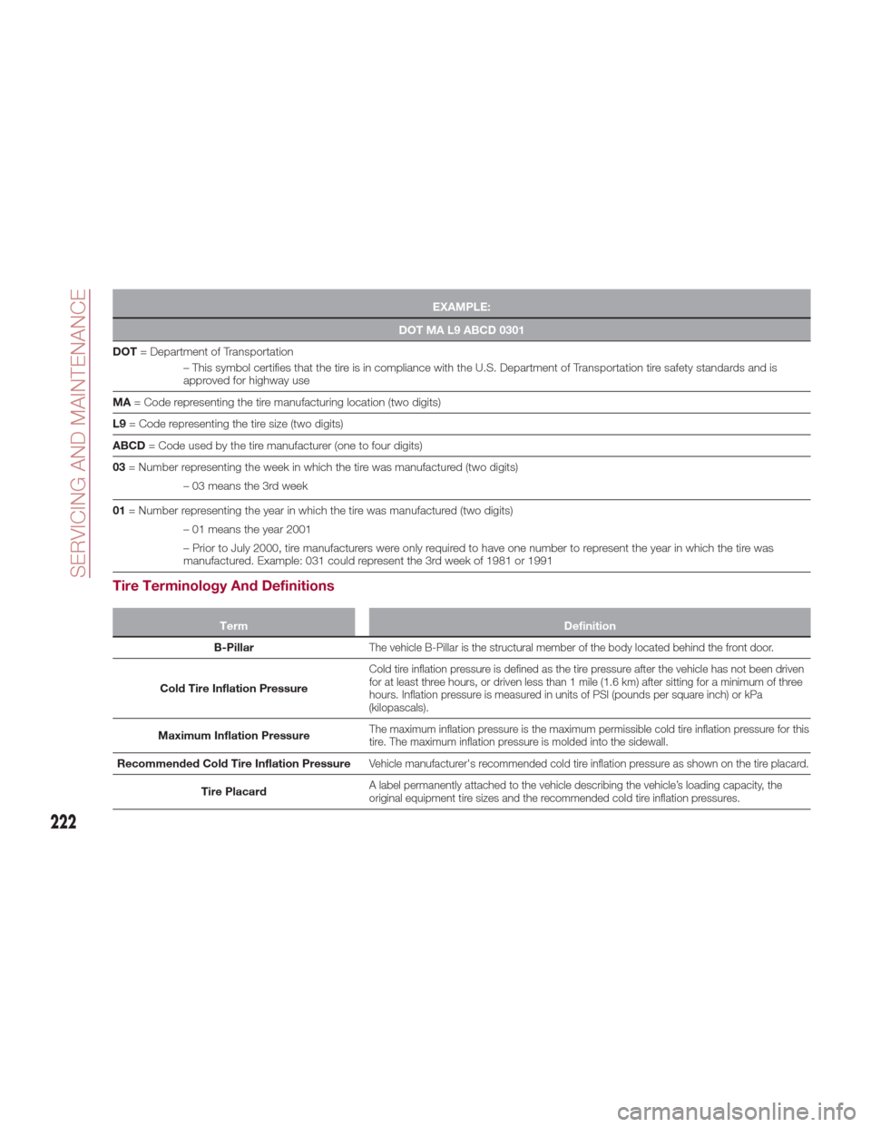
EXAMPLE:
DOT MA L9 ABCD 0301
DOT =
Department of Transportation
– This symbol certifies that the tire is in compliance with the U.S. Department of Transportation tire safety standards and is
approved for highway use
MA = Code representing the tire manufacturing location (two digits)
L9 = Code representing the tire size (two digits)
ABCD = Code used by the tire manufacturer (one to four digits)
03 = Number representing the week in which the tire was manufactured (two digits)
– 03 means the 3rd week
01 = Number representing the year in which the tire was manufactured (two digits)
– 01 means the year 2001
– Prior to July 2000, tire manufacturers were only required to have one number to represent the year in which the tire was
manufactured. Example: 031 could represent the 3rd week of 1981 or 1991
Tire Terminology And Definitions
Term Definition
B-Pillar
The vehicle B-Pillar is the structural member of the body located behind the front door.
Cold Tire Inflation Pressure
Cold tire inflation pressure is defined as the tire pressure after the vehicle has not been driven
for at least three hours, or driven less than 1 mile (1.6 km) after sitting for a minimum of three
hours. Inflation pressure is measured in units of PSI (pounds per square inch) or kPa
(kilopascals).
Maximum Inflation PressureThe maximum inflation pressure is the maximum permissible cold tire inflation pressure for this
tire. The maximum inflation pressure is molded into the sidewall.
Recommended Cold Tire Inflation PressureVehicle manufacturer's recommended cold tire inflation pressure as shown on the tire placard.
Tire PlacardA label permanently attached to the vehicle describing the vehicle’s loading capacity, the
original equipment tire sizes and the recommended cold tire inflation pressures.
222
SERVICING AND MAINTENANCE
Page 225 of 268
Tire Loading And Tire Pressure
Note:
The proper cold tire inflation pressure is
listed on the driver’s side B-Pillar or the
rear edge of the driver's side door.Tire And Loading Information
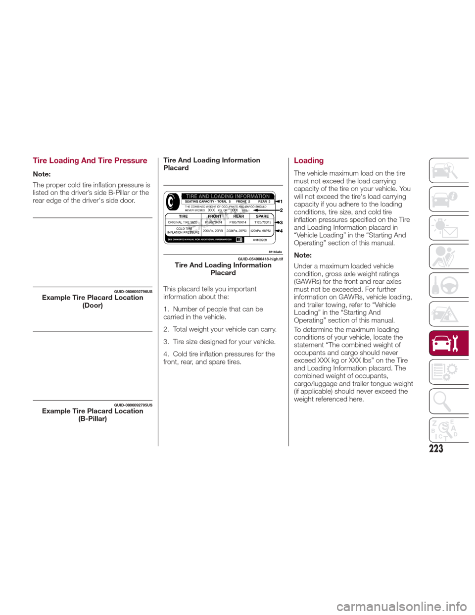
Placard
This placard tells you important
information about the:
1. Number of people that can be
carried in the vehicle.
2. Total weight your vehicle can carry.
3. Tire size designed for your vehicle.
4. Cold tire inflation pressures for the
front, rear, and spare tires.
Loading
The vehicle maximum load on the tire
must not exceed the load carrying
capacity of the tire on your vehicle. You
will not exceed the tire's load carrying
capacity if you adhere to the loading
conditions, tire size, and cold tire
inflation pressures specified on the Tire
and Loading Information placard in
“Vehicle Loading” in the “Starting And
Operating” section of this manual.
Note:
Under a maximum loaded vehicle
condition, gross axle weight ratings
(GAWRs) for the front and rear axles
must not be exceeded. For further
information on GAWRs, vehicle loading,
and trailer towing, refer to “Vehicle
Loading” in the “Starting And
Operating” section of this manual.
To determine the maximum loading
conditions of your vehicle, locate the
statement “The combined weight of
occupants and cargo should never
exceed XXX kg or XXX lbs” on the Tire
and Loading Information placard. The
combined weight of occupants,
cargo/luggage and trailer tongue weight
(if applicable) should never exceed the
weight referenced here.
GUID-0806092796USExample Tire Placard Location
(Door)
GUID-0806092795USExample Tire Placard Location(B-Pillar)
GUID-054900418-high.tifTire And Loading InformationPlacard
223
Page 226 of 268
Steps For Determining Correct
Load Limit—
(1) Locate the statement “The
combined weight of occupants and
cargo should never exceed XXX kg
or XXX lbs.” on your vehicle's
placard.
(2) Determine the combined weight
of the driver and passengers that
will be riding in your vehicle.
(3) Subtract the combined weight of
the driver and passengers from XXX
kg or XXX lbs.
(4) The resulting figure equals the
available amount of cargo and
luggage load capacity. For
example, if “XXX” amount equals
1400 lbs. and there will be five
150 lb passengers in your vehicle,
the amount of available cargo and
luggage load capacity is 650 lbs.
(1400-750 (5x150) = 650 lbs.)(5) Determine the combined weight
of luggage and cargo being loaded
on the vehicle. That weight may not
safely exceed the available cargo
and luggage load capacity
calculated in Step 4.
(6) If your vehicle will be towing a
trailer, load from your trailer will be
transferred to your vehicle. Consult
this manual to determine how this
reduces the available cargo and
luggage load capacity of your
vehicle.
Metric Example For Load Limit
For example, if “XXX” amount equals
635 kg and there will be five 68 kg
passengers in your vehicle, the amount
of available cargo and luggage load
capacity is 295 kg (635-340 (5x68) =
295 kg) as shown in step 4.
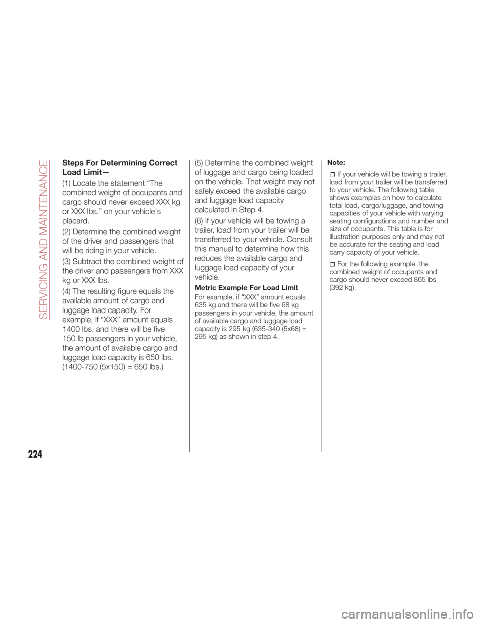
Note:
If your vehicle will be towing a trailer,
load from your trailer will be transferred
to your vehicle. The following table
shows examples on how to calculate
total load, cargo/luggage, and towing
capacities of your vehicle with varying
seating configurations and number and
size of occupants. This table is for
illustration purposes only and may not
be accurate for the seating and load
carry capacity of your vehicle.
For the following example, the
combined weight of occupants and
cargo should never exceed 865 lbs
(392 kg).
224
SERVICING AND MAINTENANCE
Page 227 of 268
Warning!
Overloading of your tires is dangerous. Overloading can cause tire failure, affect vehicle handling, and increase your stopping distance. Use
tires of the recommended load capacity for your vehicle. Never overload them.
GUID-054900419-high.tif
225
Page 233 of 268
recommended safe operating speeds,
loading and cold tire inflation pressures.
Warning!
High speed driving with your vehicle under
maximum load is dangerous. The added
strain on your tires could cause them to
fail. You could have a serious collision. Do
not drive a vehicle loaded to the maximum
capacity at continuous speeds above
75 mph (120 km/h).
Radial Ply Tires
Warning!
Combining radial ply tires with other types
of tires on your vehicle will cause your
vehicle to handle poorly. The instability
could cause a collision. Always use radial
ply tires in sets of four. Never combine
them with other types of tires.
Tire Repair
If your tire becomes damaged, it may
be repaired if it meets the following
criteria:
The tire has not been driven on when
flat.
The damage is only on the tread
section of your tire (sidewall damage is
not repairable).
The puncture is no greater than a ¼
of an inch (6 mm).
Consult an authorized tire dealer for tire
repairs and additional information.
Damaged Run Flat tires, or Run Flat
tires that have experienced a loss of
pressure should be replaced
immediately with another Run Flat tire
of identical size and service description
(Load Index and Speed Symbol).
Run Flat Tires — If Equipped
Run Flat tires allow you the capability to
drive 50 miles (80 km) at 50 mph
(80 km/h) after a rapid loss of inflation
pressure. This rapid loss of inflation is
referred to as the Run Flat mode. A Run
Flat mode occurs when the tire inflation
pressure is of/or below 14 psi (96 kPa).
Once a Run Flat tire reaches the run flat
mode it has limited driving capabilities
and needs to be replaced immediately.
A Run Flat tire is not repairable.
It is not recommended driving a vehicle
loaded at full capacity or to tow a trailer
while a tire is in the run flat mode.
See the tire pressure monitoring section
for more information.
Tire Spinning
When stuck in mud, sand, snow, or ice
conditions, do not spin your vehicle's
wheels above 30 mph (48 km/h) or for
longer than 30 seconds continuously
without stopping.
Warning!
Fast spinning tires can be dangerous.
Forces generated by excessive wheel
speeds may cause tire damage or failure. A
tire could explode and injure someone. Do
not spin your vehicle's wheels faster than
30 mph (48 km/h) for more than
30 seconds continuously when you are
stuck, and do not let anyone near a
spinning wheel, no matter what the speed.
Tread Wear Indicators
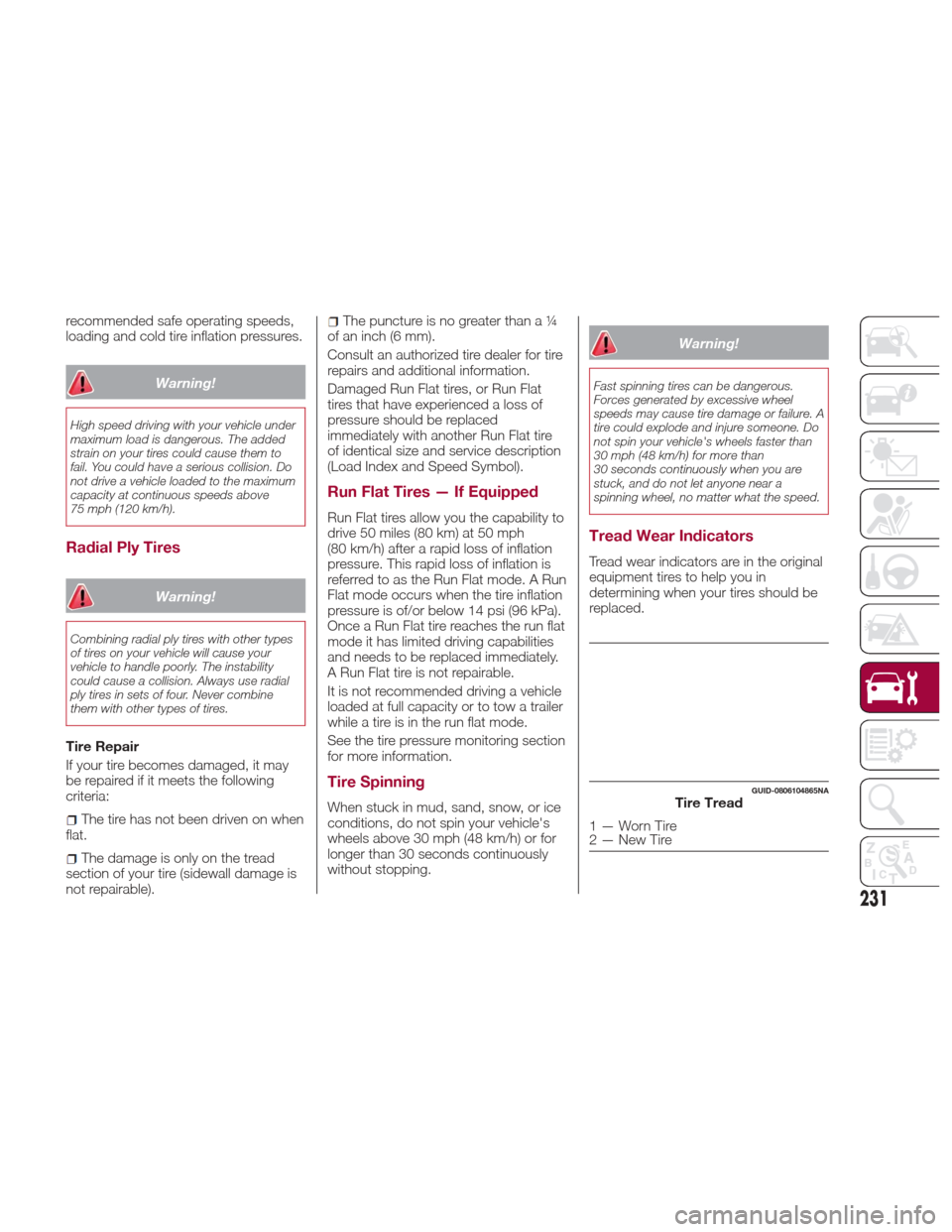
Tread wear indicators are in the original
equipment tires to help you in
determining when your tires should be
replaced.
GUID-0806104865NATire Tread
1—WornTire
2—NewTire
231
Page 235 of 268

Warning!
Do not use a tire, wheel size, load rating,
or speed rating other than that specified for
your vehicle. Some combinations of
unapproved tires and wheels may change
suspension dimensions and performance
characteristics, resulting in changes to
steering, handling, and braking of your
vehicle. This can cause unpredictable
handling and stress to steering and
suspension components. You could lose
control and have a collision resulting in
serious injury or death. Use only the tire
and wheel sizes with load ratings approved
for your vehicle.
Never use a tire with a smaller load
index or capacity, other than what was
originally equipped on your vehicle. Using a
tire with a smaller load index could result in
tire overloading and failure. You could lose
control and have a collision.
Failure to equip your vehicle with tires
having adequate speed capability can
result in sudden tire failure and loss of
vehicle control.
Caution!
Replacing original tires with tires of a
different size may result in false
speedometer and odometer readings.
DEPARTMENT OF
TRANSPORTATION
UNIFORM TIRE
QUALITY GRADES
The following tire grading categories
were established by the National
Highway Traffic Safety Administration.
The specific grade rating assigned by
the tire's manufacturer in each category
is shown on the sidewall of the tires on
your vehicle.
All passenger vehicle tires must
conform to Federal safety requirements
in addition to these grades.
Treadwear
The Treadwear grade is a comparative
rating, based on the wear rate of the
tire when tested under controlled
conditions on a specified government
test course. For example, a tire graded
150 would wear one and one-half times
as well on the government course as a
tire graded 100. The relative
performance of tires depends upon the
actual conditions of their use, however,
and may depart significantly from the
norm due to variations in driving habits,
service practices, and differences in
road characteristics and climate.
Traction Grades
The Traction grades, from highest to
lowest, are AA, A, B, and C. These
grades represent the tire's ability to
stop on wet pavement, as measured
under controlled conditions on specified
government test surfaces of asphalt
and concrete. A tire marked C may
have poor traction performance.
Warning!
The traction grade assigned to this tire is
based on straight-ahead braking traction
tests, and does not include acceleration,
cornering, hydroplaning, or peak traction
characteristics.
233
Page 264 of 268
Heated Mirrors...............34
High Beam Headlights ..........35
Automatic High Beam
Headlights ................36
Hill Start Assist (HSA) System .....98
Hood.....................52
Hood Release ...............52
Identification data ............239
Ignition ....................17
Installing electrical/electronic devices ...................3
Instrument Cluster Display Instrument Cluster Display .....64
Reconfigurable Instrument
Cluster Display .............64
Instrument Panel Features Instrument Panel Features ......62
Interior Ambient Lighting .........38
Interior Lights ................37
Interiors (cleaning) ............237
Internal Equipment ............55
Jack Operation.............220
Jump Starting ............196,197
Key Fob
Remote Keyless Entry ........14
Keyless Entry System/Immobilizer System ..................18
Lane Change ...............36
Lane Change And Turn Signals ....36Lane Departure Warning System . . .167
LaneSense
............... .167
Lap/Shoulder Belts ...........110
Life Of Tires ............... .232
Lifting The Vehicle ............220
Light bulbs types of bulbs ............181
Light Switch ................34
Lights AirBag ............... .115
Automatic Headlights ........34
Courtesy/Reading ......37,38,39
Daytime Running ...........35
Hazard Warning Flasher ......180
Headlight Switch .........34,35
Headlights .............34,35
High Beam ...............35
Instrument Cluster ........34,35
Intensity Control ............39
Interior ...............38,39
Map Reading .............37
Park ...................35
Reading .................37
Turn Signal ...............36
Loading Vehicle .............173
Tires ................. .223
Luggage compartment light (bulb replacement) ..............184
Luggage/Cargo Capacity ........53
Manual, Service.............259
Methanol ................. .249
Mirrors Automatic Dimming .........33
Electric Powered ...........33
Electric Remote ............33
Heated .................34
OBD System ...............94
Occupant Restraints ..........108
Overheating, Engine ...........199
Owner's Manual (Operator Manual) ..........259
Paintwork (cleaning and
maintenance) .............235
Panic Brake Assist (PBA) System . . .98
Park Sensors system ..........163
Passive Entry (system) ..........22
Performance (top speed) ........254
Pets .................... .133
Placard, Tire And Loading Information ...............223
Power Mirrors .................33
Seats ..................27
Sunroof .................50
Power Sunroof ...............50
Power supply ...............241
Power windows ..............49
Pregnant Women And Seat Belts . .113
INDEX