park assist Alfa Romeo Giulia 2017 Owner's Manual
[x] Cancel search | Manufacturer: ALFA ROMEO, Model Year: 2017, Model line: Giulia, Model: Alfa Romeo Giulia 2017Pages: 268, PDF Size: 18.64 MB
Page 54 of 268
HOOD
Opening
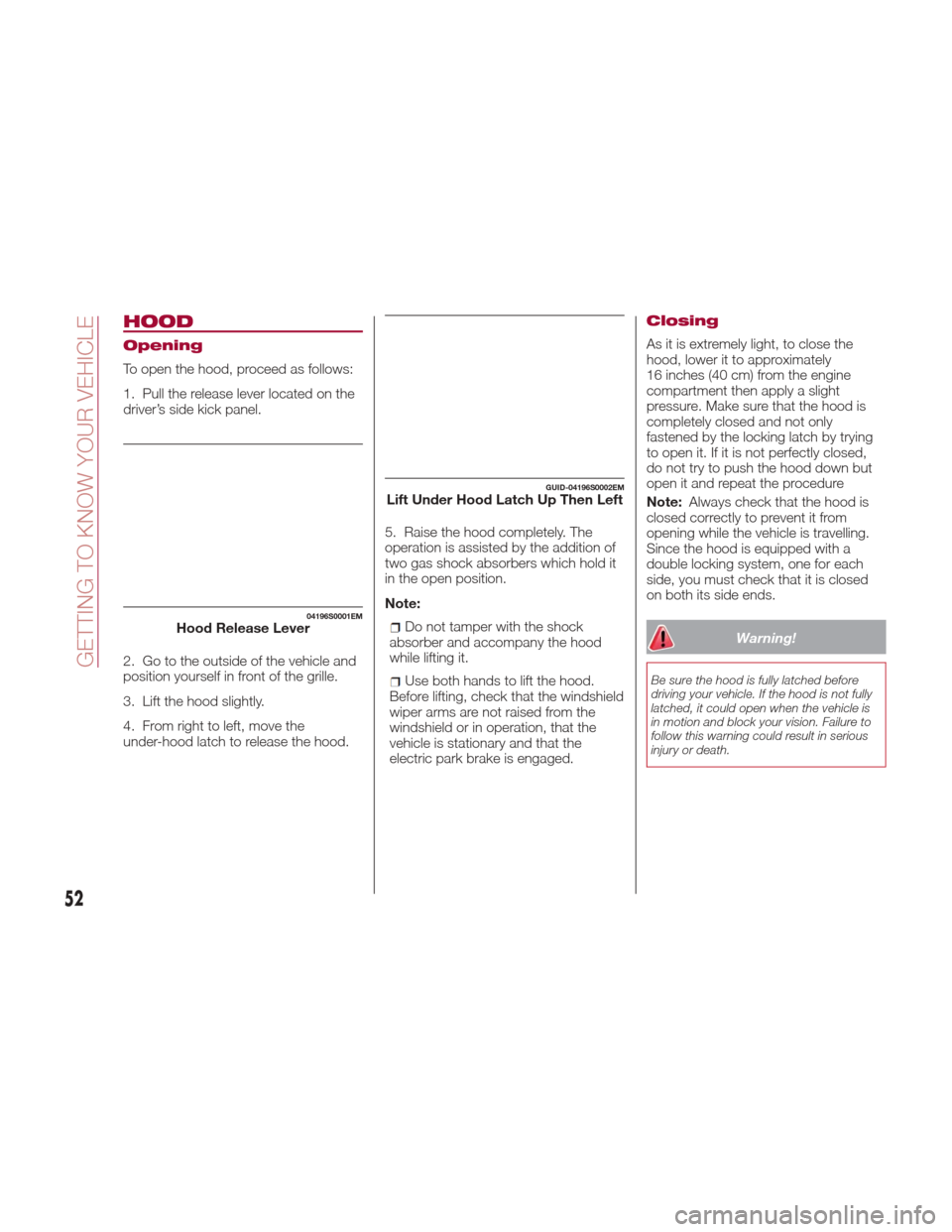
To open the hood, proceed as follows:
1. Pull the release lever located on the
driver’s side kick panel.
2. Go to the outside of the vehicle and
position yourself in front of the grille.
3. Lift the hood slightly.
4. From right to left, move the
under-hood latch to release the hood.5. Raise the hood completely. The
operation is assisted by the addition of
two gas shock absorbers which hold it
in the open position.
Note:
Do not tamper with the shock
absorber and accompany the hood
while lifting it.
Use both hands to lift the hood.
Before lifting, check that the windshield
wiper arms are not raised from the
windshield or in operation, that the
vehicle is stationary and that the
electric park brake is engaged.
Closing
As it is extremely light, to close the
hood, lower it to approximately
16 inches (40 cm) from the engine
compartment then apply a slight
pressure. Make sure that the hood is
completely closed and not only
fastened by the locking latch by trying
to open it. If it is not perfectly closed,
do not try to push the hood down but
open it and repeat the procedure
Note: Always check that the hood is
closed correctly to prevent it from
opening while the vehicle is travelling.
Since the hood is equipped with a
double locking system, one for each
side, you must check that it is closed
on both its side ends.
Warning!
Be sure the hood is fully latched before
driving your vehicle. If the hood is not fully
latched, it could open when the vehicle is
in motion and block your vision. Failure to
follow this warning could result in serious
injury or death.
04196S0001EMHood Release Lever
GUID-04196S0002EMLift Under Hood Latch Up Then Left
52
GETTING TO KNOW YOUR VEHICLE
Page 140 of 268
ELECTRIC PARK
BRAKE
The vehicle is equipped with electric
park brake to guarantee better use and
optimal performance compared to a
manually operated park brake.
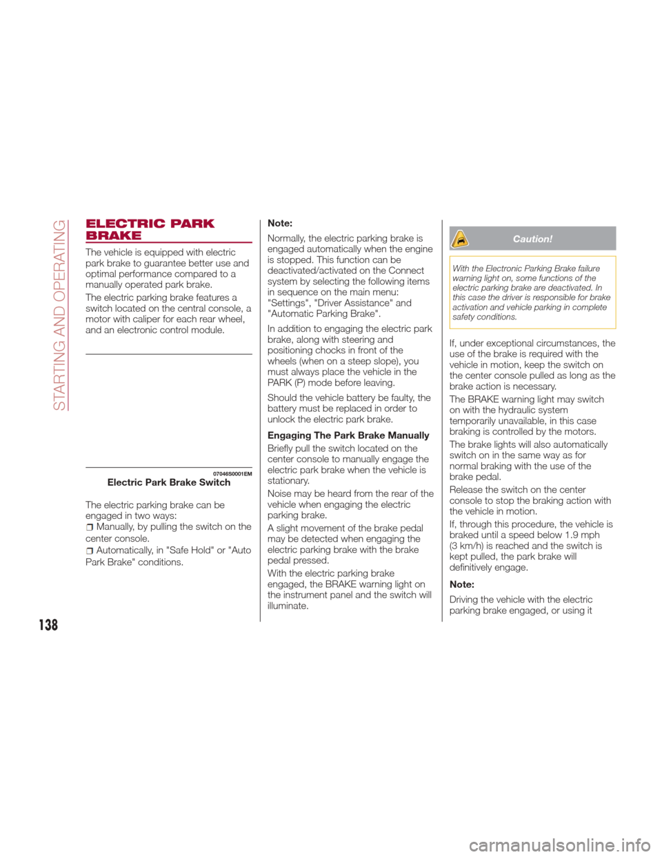
The electric parking brake features a
switch located on the central console, a
motor with caliper for each rear wheel,
and an electronic control module.
The electric parking brake can be
engaged in two ways:
Manually, by pulling the switch on the
center console.
Automatically, in "Safe Hold" or "Auto
Park Brake" conditions. Note:
Normally, the electric parking brake is
engaged automatically when the engine
is stopped. This function can be
deactivated/activated on the Connect
system by selecting the following items
in sequence on the main menu:
"Settings", "Driver Assistance" and
"Automatic Parking Brake".
In addition to engaging the electric park
brake, along with steering and
positioning chocks in front of the
wheels (when on a steep slope), you
must always place the vehicle in the
PARK (P) mode before leaving.
Should the vehicle battery be faulty, the
battery must be replaced in order to
unlock the electric park brake.
Engaging The Park Brake Manually
Briefly pull the switch located on the
center console to manually engage the
electric park brake when the vehicle is
stationary.
Noise may be heard from the rear of the
vehicle when engaging the electric
parking brake.
A slight movement of the brake pedal
may be detected when engaging the
electric parking brake with the brake
pedal pressed.
With the electric parking brake
engaged, the BRAKE warning light on
the instrument panel and the switch will
illuminate.
Caution!
With the Electronic Parking Brake failure
warning light on, some functions of the
electric parking brake are deactivated. In
this case the driver is responsible for brake
activation and vehicle parking in complete
safety conditions.
If, under exceptional circumstances, the
use of the brake is required with the
vehicle in motion, keep the switch on
the center console pulled as long as the
brake action is necessary.
The BRAKE warning light may switch
on with the hydraulic system
temporarily unavailable, in this case
braking is controlled by the motors.
The brake lights will also automatically
switch on in the same way as for
normal braking with the use of the
brake pedal.
Release the switch on the center
console to stop the braking action with
the vehicle in motion.
If, through this procedure, the vehicle is
braked until a speed below 1.9 mph
(3 km/h) is reached and the switch is
kept pulled, the park brake will
definitively engage.
Note:
Driving the vehicle with the electric
parking brake engaged, or using it
07046S0001EMElectric Park Brake Switch
138
STARTING AND OPERATING
Page 147 of 268
Brake/Transmission
Shift Interlock System
This vehicle is equipped with a Brake
Transmission Shift Interlock system
(BTSI) that holds the gear selector in
PARK (P) unless the brakes are applied.
This system prevents you from moving
the gear selector from position PARK
(P) unless the brakes are applied.
To shift the transmission out of PARK
(P), the ignition must be cycled to the
AVV mode (engine running or not) and
the brake pedal must be pressed.
Brake/Transmission Shift Interlock
Disabling
Only if strictly necessary (e.g. pushing
the vehicle, conveyor vehicle washing
systems) inhibit the automatic activation
of PARK (P) mode when stopping the
engine, or proceed as described below:
1. Car at a standstill.
2. NEUTRAL (N) mode activated.
3. Push the ignition button for at least
three seconds.
The automatic park brake engagement
function when the engine is stopped
can also be deactivated on the Connect
system by selecting the following
functions on the main menu: "Settings",
"Driver Assistance" and "Automatic
Parking Brake".
Important Notes
Failure to comply with what is reported
below may damage the transmission:
Shift into PARK (P) mode only with
the vehicle at a standstill.
Select REVERSE (R) mode, or pass
from REVERSE to another mode only
with the vehicle at a standstill and
engine idling.
Do not change between PARK (P),
REVERSE (R), NEUTRAL (N) or DRIVE
(D) modes with engine running at a
speed above idling.
Before activating any transmission
operating mode, fully depress the brake
pedal.
Note: The unexpected movement of
the vehicle can injure the occupants or
people nearby. Do not leave the vehicle
with engine running: before getting out
of the passenger compartment always
engage the electric park brake, select
the PARK (P) mode, stop the engine.
With the ignition device in the STOP
position, the transmission is locked in
the PARK (P) position in order to
prevent accidental vehicle movement. If
equipped with keyless ignition, do not
leave the key fob near the vehicle (or in
a place accessible to children), and do
not leave the ignition on. A child could activate the electric
windows, other controls, or even start
the engine; it is dangerous to select a
mode other than PARK (P) or NEUTRAL
(N) at an engine speed higher than
idling.
If the brake pedal is not fully depressed,
the vehicle could rapidly accelerate.
Only engage the gear with engine at
idling while fully depressing the brake
pedal. If the transmission temperature
exceeds the normal operating limits, the
transmission control unit may change
the gear engagement order and reduce
the drive torque. If the transmission
overheats, the display shows the
symbol. In this case, the
transmission could operate incorrectly
until it cools down.
When using the vehicle with extremely
low external temperatures, the
transmission operation may change
depending on the engine and
transmission temperature, as well as
vehicle speed. Activation of the torque
converter clutch and of the eighth or
ninth gear is inhibited until the
transmission oil is correctly warmed up.
Complete operation of the transmission
will be enabled as soon as the fluid
temperature reaches the predefined
value.
145
Page 152 of 268
If the system fails, the following symbol
will appear in the instrument cluster
display
.
STOP/START EVO
Stop/Start Evo
The Stop/Start Evo system
automatically shuts off the engine
during a vehicle stop if the required
conditions are met. Releasing the brake
pedal or accelerator pedal will
automatically restart the engine.
The function was developed to increase
vehicle efficiency by reducing fuel
consumption, gas emissions, and
sound pollution.
Operating Mode
Stopping the Engine
With vehicle at a standstill and brake
pedal pressed, the engine switches off
if the gear selector is in a position other
than REVERSE (R).
The system does not operate when the
gear selector is in REVERSE (R), in
order to making parking maneuvers
easier.
In the event of stops uphill, engine
switching off is disabled to make the
"Hill Start Assist" function available
(works only with running engine).NOTE: The engine can only be
automatically stopped after having run
at about 6 mph (10 km/h). After an
automatic restart, to stop the engine
you only need to move the vehicle
exceed a speed of 0.3 mph (0.5 km/h).
Engine stopping is signaled by the
symbol lighting up on the instrument
cluster display.
Restarting the Engine
To restart the engine, release the brake
pedal.
With brake pressed, if the gear selector
is in automatic mode - DRIVE (D) - the
engine can be restarted by moving the
gear selector to REVERSE (R) or
NEUTRAL (N) or "AutoStick".
With brake pressed, if the gear selector
is in "AutoStick" mode, the engine can
be restarted by moving the gear
selector to "+" or "–", or REVERSE (R)
or NEUTRAL (N).
When the engine has been stopped
automatically, keeping the brake pedal
pressed, the brake can be released
keeping the engine off by quickly
shifting the gear selector to PARK (P).
To restart the engine, just move the
gear selector out of a position other
than PARK (P).
04306S0001EMAlfa Active Suspension Button
150
STARTING AND OPERATING
Page 158 of 268

ADAPTIVE CRUISE
CONTROL (ACC) —
IF EQUIPPED
System Description
The Adaptive Cruise Control (ACC) is a
driver assist system that combines the
speed control functions for controlling
the distance from the vehicle ahead.
The system allows to set and hold the
vehicle at the desired speed without
needing to press the accelerator. It also
allows to set and hold a distance from
the vehicle ahead (these settings are set
by the driver).
The Adaptive Cruise Control (ACC) uses
a radar sensor located behind the front
bumper and a camera located in the
center/upper part of the windshield, to
detect the presence of a vehicle close
ahead.This system enhances driving comfort
while on the highway or out of town
with light traffic.
Warning!
Adaptive Cruise Control (ACC) is a
convenience system. It is not a substitute
for active driving involvement. It is always
the driver’s responsibility to be attentive of
road, traffic, and weather conditions,
vehicle speed, distance to the vehicle
ahead; and, most importantly, brake
operation to ensure safe operation of the
vehicle under all road conditions. Your
complete attention is always required while
driving to maintain safe control of your
vehicle. Failure to follow these warnings
can result in a collision and death or
serious personal injury.
The ACC system:
Does not react to pedestrians,
oncoming vehicles, and stationary objects
(e.g., a stopped vehicle in a traffic jam or a
disabled vehicle).
Cannot take street, traffic, and weather
conditions into account, and may be
limited upon adverse sight distance
conditions.
Does not always fully recognize complex
driving conditions, which can result in
wrong or missing distance warnings.
Will bring the vehicle to a complete stop
while following a target vehicle and hold the
vehicle for approximately 3 minutes in the
stop position. If the target vehicle does not
start moving within 3 minutes the parking
brake will be activated, and the ACC
system will be canceled.
You should switch off the ACC system:
When driving in fog, heavy rain, heavy
snow, sleet, heavy traffic, and complex
driving situations (i.e., in highway
construction zones).
When entering a turn lane or highway off
ramp; when driving on roads that are
winding, icy, snow-covered, slippery, or
have steep uphill or downhill slopes.
When circumstances do not allow safe
driving at a constant speed.
GUID-06016S0003EMFront Bumper Radar Location
06016S0004EMWindshield Camera Location
156
STARTING AND OPERATING
Page 165 of 268

PARKSENSE
SYSTEM — IF
EQUIPPED
Vehicles With Rear
Sensors Only
The parking sensors, located in the rear
bumper, detect obstacles while the
vehicle is in REVERSE. When an
obstacle is detected, an acoustic alert
will sound and, if equipped, visual
indications will be displayed on the
instrument cluster.
Engagement/Disengagement
To turn the system off, push the
ParkSense switch located to the left of
the headlight switch. The indicator light
within the switch will light up when the
system is turned off. Pushing the switch
a second time will turn the system back
on, and the indicator light will turn off.The indicator light within the ParkSense
switch will also be on in case of system
failure. If the switch is pushed with a
system failure, the indicator light will
flash for approximately five seconds.
The light will then stay on constantly.
System Activation/Deactivation
The system, when engaged, is
automatically activated by engaging the
REVERSE gear. It is deactivated by
engaging another gear.
Acoustic Signal
When REVERSE is engaged and there
is an obstacle behind the vehicle, an
acoustic signal with variable frequency
will sound.
The acoustic signal increases in
frequency as the distance between the
vehicle and the obstacle decreases.
The acoustic signal becomes
continuous when the distance between the vehicle and the obstacle is less than
11 inches (30 cm), and stops if the
distance increases.
The acoustic signal is constant if the
distance between the vehicle and the
obstacle is unchanged.
Note: If several obstacles are detected
by the sensors, only the nearest one is
considered.
Indication On Display
The driver can select the type of
warning they would like to be displayed
through the Connect system. To access
the function on the main menu, select in
the following order:
1. “Settings”
2. “Driver Assistance”
3. “ParkSense”
4. “Mode”
5. “Sound-Display”
Visual Indications
The system indicates the presence of
an obstacle by displaying a single arc in
the detected area, in relation to the
distance of the object and the position
of the vehicle.
If the obstacle is detected in the rear
central area, a single arc will be
displayed as the obstacle approaches,
first constant, then flashing, in addition
to an acoustic signal.
GUID-07176S0001EMRear Sensor Location
07176S0052EMParkSense System On/Off Switch
163
Page 168 of 268
Note:If the sensors detect several
front and rear obstacles, the closest
obstacle is considered. An intermittent
signal will sound if the obstacles are at
the same distance (front and rear).
When the system emits an acoustic
signal, the volume of the Connect
system, if activated, is automatically
lowered.
Indication On Display
The driver can select the type of
warning they would like to be displayed
through the Connect system. To access
the function on the main menu, select in
the following order:
1. “Settings”
2. “Driver assistance”
3. “Park Sensors”
4. “Mode”
5. “Sound-Display”
Visual Indications
The system indicates the presence of
an obstacle by displaying a single arc in
the detected areas, in relation to the
distance of the object and the position
of the vehicle.
If the obstacle is detected in the front or
rear central area, a single arc will be
displayed as the obstacle approaches,
first constant, then flashing, in addition
to an acoustic signal. If the obstacle is detected in the front or
rear left and/or right area, a single
flashing arc will be shown in the
corresponding area on the display and
the system will emit an acoustic signal,
either at frequent intervals or constantly.
If several obstacles are detected
simultaneously in the front and rear
area, the display will show all of them,
regardless of the area in which they
were detected.
In general, the vehicle is closer to the
obstacle when a single or several
flashing arcs are shown on the display
and the acoustic signal becomes
continuous. The color on the display
depends on the distance from and
position of the obstacle.
It is possible to exit from the display
screen by pressing the Rotary Pad,
however, the acoustic alert will remain
active.
Fault Indication
Parking sensor faults, if any, will be
indicated by a message on the display
on the instrument cluster. Refer to
"Warning Lights And Messages" in
"Getting To Know Your Instrument
Panel".
Messages On The Display
In case of system failure, a dedicated
message appears on the instrument
cluster for about 5 seconds.Cleaning the front or rear
sensors: If the display shows a
message requiring the sensors to be
cleaned, make sure that the outer
surface and the underside of the front
and rear bumpers are free of debris
(e.g. snow, mud, ice, etc.). Once these
areas are clear, place the ignition in
STOP mode. Then, return it to ON
mode. If the message is still displayed,
contact an authorized dealer.
Audio system not available :Ifthe
display shows a message that the
audio system is not available, it means
that the acoustic signal will be emitted
by the instrument panel, and not
through the vehicles speakers.
Note: Some conditions may influence
the performance of the ParkSense
system:
Reduced sensor sensitivity could
be due to the presence of ice, snow,
mud, or thick paint on the surface of
the sensor.
The sensors may detect a false
obstacle (echo interference) due to
mechanical interference, for example
when washing the vehicle or in
extreme weather.
The signals sent by the sensors can
be altered by the presence of
ultrasonic systems (e.g. pneumatic
brake systems of trucks or pneumatic
drills) near the vehicle.
166
STARTING AND OPERATING
Page 173 of 268

Rear Back-Up Camera Features
To activate the Rear Back-Up Camera
features, select “Settings” from the
Main Menu of the Connect System.
Under “Driver Assistance”, Rear
Back-Up Camera features can be
selected:
View
Camera Delay
Camera Guidelines
Selecting “View” will activate the
camera view on the display.
Selecting “Camera Delay” will allow the
camera view to remain on the display
shortly after the vehicle is no longer in
REVERSE, followed by the previously
active screen. Selecting “Camera Guidelines” will
activate the display of the dynamic
guidelines that indicate the route of the
vehicle.
Warning!
Drivers must be careful when backing up
even when using the Rear Back Up
Camera. Always check carefully behind
your vehicle, and be sure to check for
pedestrians, animals, other vehicles,
obstructions, or blind spots before backing
up. You are responsible for the safety of
your surroundings and must continue to
pay attention while backing up. Failure to
do so can result in serious injury or death.
Caution!
To avoid vehicle damage, Rear Back Up
Camera should only be used as a parking
aid. The Rear Back Up Camera is unable to
view every obstacle or object in your drive
path.
To avoid vehicle damage, the vehicle
must be driven slowly when using the Rear
Back Up Camera to be able to stop in time
when an obstacle is seen. It is
recommended that the driver look
frequently over his/her shoulder when using
the Rear Back Up Camera.
Symbols And Messages
On The Display
Indications On The Display
Through the Connect system settings,
by activating the "Camera Guidelines"
feature, guidelines can be seen on the
rear camera display. If activated, the
guidelines are positioned on the image
to highlight the width of the vehicle and
the expected reverse path based on the
steering wheel position.
A superimposed central line indicates
the center of the vehicle to assist in rear
parking maneuvers or tow hook
alignment. The various colored areas
indicate the distance from the rear of
the vehicle.
The table below shows the approximate
distances for each area:
Area Distance from the
rear of the vehicle
Red 0–11.8
inches
(0–30 cm)
Yellow 11.8 inches to 3.3 feet
(30 cm–1 m)
Green 3.3 feet or more
(1mormore)
07186S0002EMRear Back-Up Camera Display
171
Page 202 of 268
TOWING A
DISABLED VEHICLE
This section describes procedures for
towing a disabled vehicle using a
commercial towing service.
Caution!
The vehicle should be transported with
all four wheels OFF the ground on the
flatbed of a roadside assistance vehicle.
Avoid towing with only the front (or rear)
wheels lifted. When towing with only the
front (or rear) wheels lifted, in addition to
damaging the body, it could damage the
transmission.
Do not use sling-type equipment when
towing. Vehicle damage may occur.
When securing the vehicle to a flatbed
truck, do not attach to front or rear
suspension components. Damage to your
vehicle may result from improper towing.
Ensure that the Electric Park Brake is
released, and remain released, while being
towed.
Damage from improper towing is not
covered under the New Vehicle Limited
Warranty.
The operators of the assistance vehicle
must be informed of your vehicle's
minimum required height from the
ground, in order to avoid contact
between the ends of the bumpers and
the equipment of the breakdown truck.
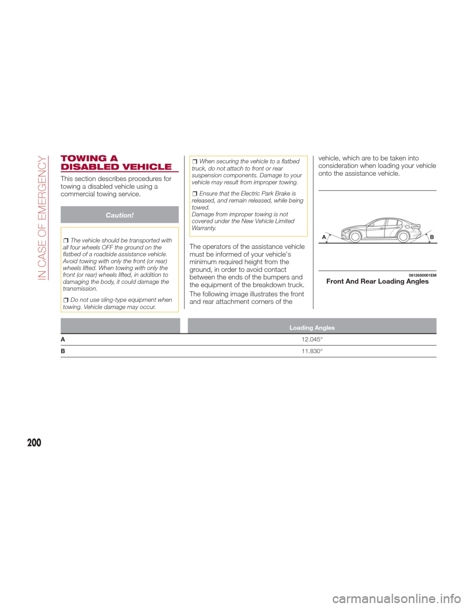
The following image illustrates the front
and rear attachment corners of the vehicle, which are to be taken into
consideration when loading your vehicle
onto the assistance vehicle.
Loading Angles
A 12.045°
B 11.830°
08126S0001EMFront And Rear Loading Angles
200
IN CASE OF EMERGENCY
Page 203 of 268
Rear Wheel Drive (RWD)
Models
It is recommended to tow the vehicle
with all four wheels OFF the ground on
the flatbed of a roadside assistance
vehicle.
Caution!
Do not use sling type equipment when
towing. Vehicle damage may occur.
When securing the vehicle to a flat bed
truck, do not attach to front or rear
suspension components. Damage to your
vehicle may result from improper towing.
Ensure that the Electric Park Brake is
released, and remains released, while
being towed.
If an assistance vehicle with a flatbed is
not available, the vehicle must be
towed with the rear wheels lifted from
the ground using a trailer or special
equipment allowing lifting of the rear
wheels.
Four-Wheel Drive (AWD)
Models
It is recommended to tow the vehicle
with all four wheels OFF the ground on
the flatbed of a roadside assistance
vehicle.
Caution!
DO NOT flat tow this vehicle. Damage to
the drivetrain will result.
DO NOT dolly tow this vehicle. Use of a
towing dolly can cause significant damage
to your vehicle.
Towing this vehicle in violation of the above
requirements can cause severe
transmission damage. Damage from
improper towing is not covered under the
New Vehicle Limited Warranty.
TOW HOOKS
If the vehicle has been in an accident or
has broken down, a tow hook is
provided in the tools container located
inside the luggage compartment for
vehicle towing. Towing is meant only for
short distances on a paved road
surface.
Proceed as follows to use the tow
hook:
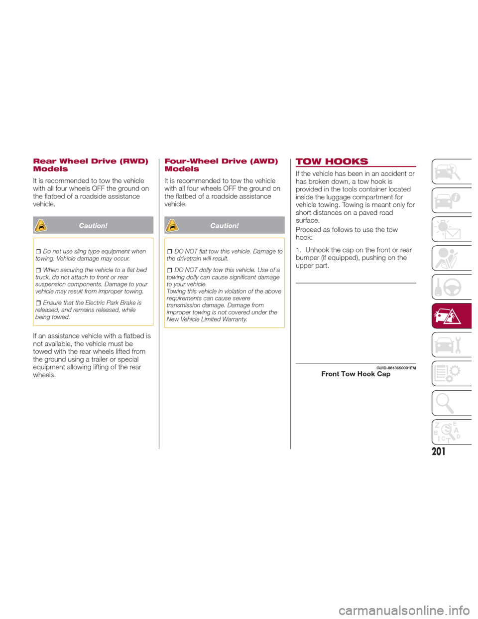
1. Unhook the cap on the front or rear
bumper (if equipped), pushing on the
upper part.
GUID-08136S0001EMFront Tow Hook Cap
201