wheel Alfa Romeo Giulia 2019 Owner's Manual
[x] Cancel search | Manufacturer: ALFA ROMEO, Model Year: 2019, Model line: Giulia, Model: Alfa Romeo Giulia 2019Pages: 232, PDF Size: 4.87 MB
Page 6 of 232
USE OF THE OWNER HANDBOOK
OPERATING INSTRUCTIONS
Each time direction instructions (left/right or forwards/backwards) about the vehicle are given, these must be understood as
regarding an occupant in the driver's seat. Special cases not complying with this rule will be specified as appropriate in the text.
The figures in the Owner Handbook are provided by way of example only: this might imply that some details of the image do not
correspond to the actual arrangement of your vehicle. In addition, the Handbook has been conceived considering vehicles with
steering wheel on the left side; it is therefore possible that on vehicles with steering wheel on the right side, the position or
construction of some controls is not exactly mirror-like with respect to the figure.
To identify the chapter with the information needed you can consult the index at the end of this Owner Handbook.
Chapters can be rapidly identified with dedicated graphic tabs, at the side of each odd page. A few pages further there is a key for
getting to know the chapter order and the relevant symbols in the tabs. There is in any case a textual indication of the current chapter
at the side of each even page.
WARNINGS AND PRECAUTIONS
While reading this Owner Handbook you will find a series ofWARNINGSto prevent procedures that could damage your vehicle.
There are alsoPRECAUTIONSthat must be carefully followed to prevent incorrect use of the components of the vehicle, which could
cause accidents or injuries.
Therefore allWARNINGSandPRECAUTIONSmust always be carefully followed.
WARNINGSandPRECAUTIONSare recalled in the text with the following symbols:
personal safety;
vehicle safety;
environmental protection.
NOTE These symbols, when necessary, are indicated besides the title or at the end of the line and are followed by a number. That
number recalls the corresponding warning at the end of the relevant section.
Page 11 of 232
In-depth knowledge of your new vehicle starts here.
The handbook that you are reading simply and directly explains
how it is made and how it works.
That’s why we advise you to read it seated comfortably on board,
so that you can see immediately what is described here for
yourself.
KNOWING YOUR CAR
INSTRUMENT PANEL............................10
RIGHT HAND DRIVE VERSION......................11
THEKEYS...................................12
IGNITION DEVICE..............................13
ENGINE IMMOBILIZER...........................14
ALARM SYSTEM ...............................15
DOORS.....................................16
SEATS.....................................19
HEADRESTS.................................23
STEERING WHEEL..............................24
REAR VIEW MIRRORS...........................25
EXTERNAL LIGHTS .............................26
INTERIOR LIGHTS..............................31
WINDSCREEN WIPER . ...........................31
CLIMATE CONTROL.............................33
WINDOW WINDERS.............................35
ELECTRIC SUNROOF............................36
BONNET....................................38
TAILGATE...................................39
ROOF RACK / SKI RACK..........................41
Page 12 of 232
INSTRUMENT PANEL
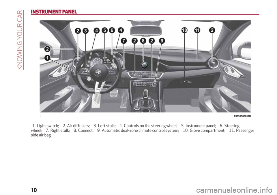
1. Light switch; 2. Air diffusers; 3. Left stalk; 4. Controls on the steering wheel; 5. Instrument panel; 6. Steering
wheel; 7. Right stalk; 8. Connect; 9. Automatic dual-zone climate control system; 10. Glove compartment; 11. Passenger
side air bag;
103036S0001EM
10
KNOWING YOUR CAR
Page 13 of 232
RIGHT HAND DRIVE VERSION
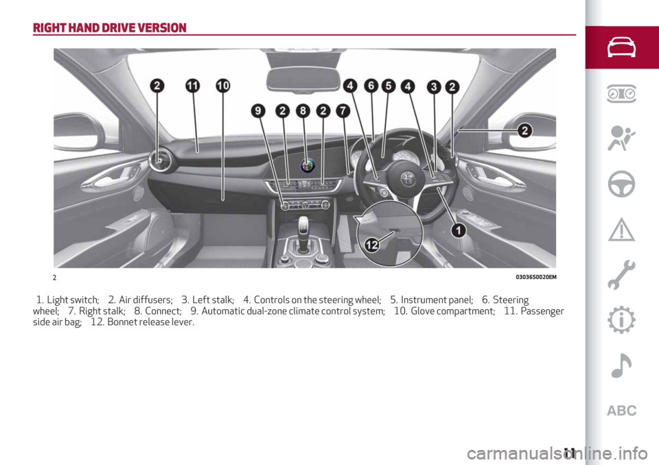
1. Light switch; 2. Air diffusers; 3. Left stalk; 4. Controls on the steering wheel; 5. Instrument panel; 6. Steering
wheel; 7. Right stalk; 8. Connect; 9. Automatic dual-zone climate control system; 10. Glove compartment; 11. Passenger
side air bag; 12. Bonnet release lever.
203036S0020EM
11
Page 15 of 232
IGNITION DEVICE
OPERATION
1) 2) 3) 4) 5)
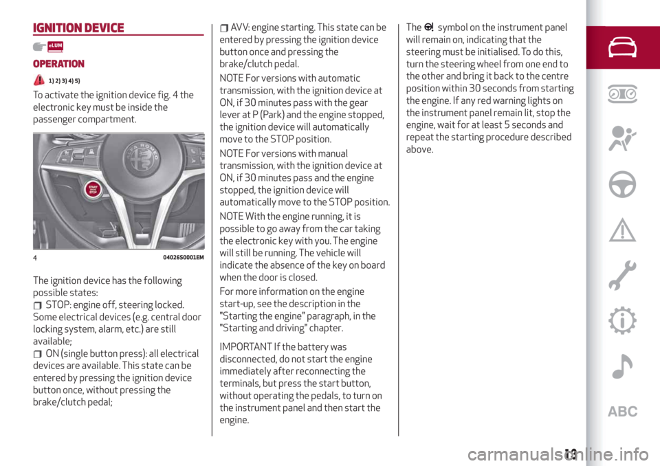
To activate the ignition device fig. 4 the
electronic key must be inside the
passenger compartment.
The ignition device has the following
possible states:
STOP: engine off, steering locked.
Some electrical devices (e.g. central door
locking system, alarm, etc.) are still
available;
ON (single button press): all electrical
devices are available. This state can be
entered by pressing the ignition device
button once, without pressing the
brake/clutch pedal;
AVV: engine starting. This state can be
entered by pressing the ignition device
button once and pressing the
brake/clutch pedal.
NOTE For versions with automatic
transmission, with the ignition device at
ON, if 30 minutes pass with the gear
lever at P (Park) and the engine stopped,
the ignition device will automatically
move to the STOP position.
NOTE For versions with manual
transmission, with the ignition device at
ON, if 30 minutes pass and the engine
stopped, the ignition device will
automatically move to the STOP position.
NOTE With the engine running, it is
possible to go away from the car taking
the electronic key with you. The engine
will still be running. The vehicle will
indicate the absence of the key on board
when the door is closed.
For more information on the engine
start-up, see the description in the
"Starting the engine" paragraph, in the
"Starting and driving" chapter.
IMPORTANT If the battery was
disconnected, do not start the engine
immediately after reconnecting the
terminals, but press the start button,
without operating the pedals, to turn on
the instrument panel and then start the
engine.The
symbol on the instrument panel
will remain on, indicating that the
steering must be initialised. To do this,
turn the steering wheel from one end to
the other and bring it back to the centre
position within 30 seconds from starting
the engine. If any red warning lights on
the instrument panel remain lit, stop the
engine, wait for at least 5 seconds and
repeat the starting procedure described
above.
404026S0001EM
13
Page 26 of 232
STEERING WHEEL
14) 15)
ADJUSTMENTS
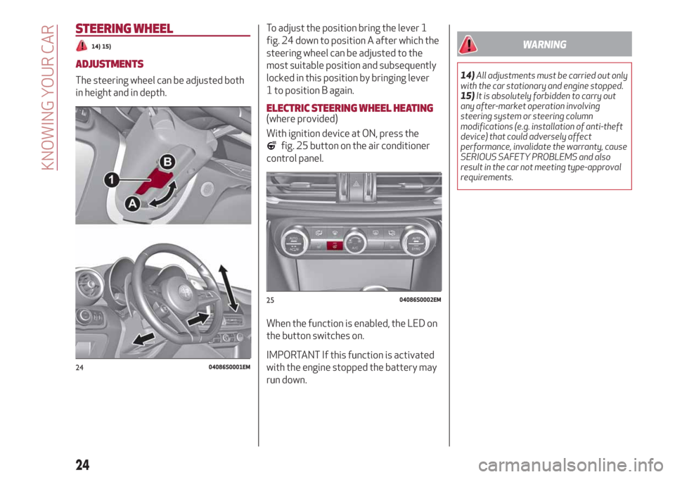
The steering wheel can be adjusted both
in height and in depth.To adjust the position bring the lever 1
fig. 24 down to position A after which the
steering wheel can be adjusted to the
most suitable position and subsequently
locked in this position by bringing lever
1 to position B again.
ELECTRIC STEERING WHEEL HEATING(where provided)
With ignition device at ON, press the
fig. 25 button on the air conditioner
control panel.
When the function is enabled, the LED on
the button switches on.
IMPORTANT If this function is activated
with the engine stopped the battery may
run down.
WARNING
14)All adjustments must be carried out only
with the car stationary and engine stopped.
15)It is absolutely forbidden to carry out
any after-market operation involving
steering system or steering column
modifications (e.g. installation of anti-theft
device) that could adversely affect
performance, invalidate the warranty, cause
SERIOUS SAFETY PROBLEMS and also
result in the car not meeting type-approval
requirements.
2404086S0001EM
2504086S0002EM
24
KNOWING YOUR CAR
Page 31 of 232
towards the steering wheel, the lights
remain on while you are operating the
lever.
Automatic high beam (AHB system)
headlights
(where provided)
The AHB system is used to switch the
high beam headlights on and off
automatically and to adapt the lighting
near towns.
Function enabling
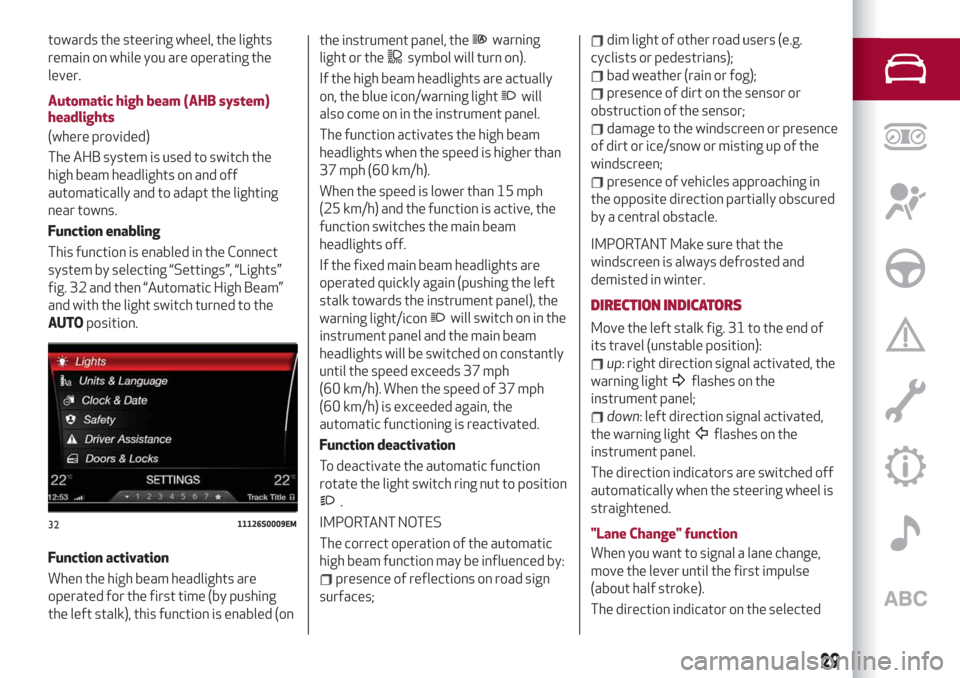
This function is enabled in the Connect
system by selecting “Settings”, “Lights”
fig. 32 and then “Automatic High Beam”
and with the light switch turned to the
AUTOposition.
Function activation
When the high beam headlights are
operated for the first time (by pushing
the left stalk), this function is enabled (onthe instrument panel, thewarning
light or the
symbol will turn on).
If the high beam headlights are actually
on, the blue icon/warning light
will
also come on in the instrument panel.
The function activates the high beam
headlights when the speed is higher than
37 mph (60 km/h).
When the speed is lower than 15 mph
(25 km/h) and the function is active, the
function switches the main beam
headlights off.
If the fixed main beam headlights are
operated quickly again (pushing the left
stalk towards the instrument panel), the
warning light/icon
will switch on in the
instrument panel and the main beam
headlights will be switched on constantly
until the speed exceeds 37 mph
(60 km/h). When the speed of 37 mph
(60 km/h) is exceeded again, the
automatic functioning is reactivated.
Function deactivation
To deactivate the automatic function
rotate the light switch ring nut to position
.
IMPORTANT NOTES
The correct operation of the automatic
high beam function may be influenced by:
presence of reflections on road sign
surfaces;
dim light of other road users (e.g.
cyclists or pedestrians);
bad weather (rain or fog);
presence of dirt on the sensor or
obstruction of the sensor;
damage to the windscreen or presence
of dirt or ice/snow or misting up of the
windscreen;
presence of vehicles approaching in
the opposite direction partially obscured
by a central obstacle.
IMPORTANT Make sure that the
windscreen is always defrosted and
demisted in winter.
DIRECTION INDICATORS
Move the left stalk fig. 31 to the end of
its travel (unstable position):
up: right direction signal activated, the
warning light
flashes on the
instrument panel;
down: left direction signal activated,
the warning light
flashes on the
instrument panel.
The direction indicators are switched off
automatically when the steering wheel is
straightened.
"Lane Change" function
When you want to signal a lane change,
move the lever until the first impulse
(about half stroke).
The direction indicator on the selected
3211126S0009EM
29
Page 34 of 232
“Smart washing” function
Pull the stalk towards the steering wheel
(unstable position) to operate the
windscreen washer.
Keep the stalk pulled to activate both the
windscreen washer jet and the
windscreen wiper with a single
movement; the latter turns on
automatically.
The windscreen wiper stops working
three strokes after the stalk is released.
A further stroke after approx. 6 seconds
completes the wiping cycle.RAIN SENSOR
This is located behind the interior rear
view mirror, in contact with the
windscreen and can detect the presence
of rain and, consequently, manage the
cleaning of the windscreen in accordance
with the amount of water on the screen.
Activation/deactivation
9) 10)
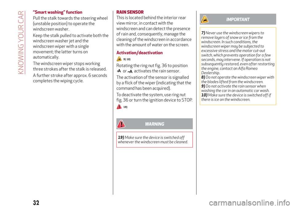
Rotating the ring nut fig. 36 to position
oractivates the rain sensor.
The activation of the sensor is signalled
by a flick of the wiper (indicating that the
command has been acquired).
To deactivate the system, use ring nut
fig. 36 or turn the ignition device to STOP.
19)
WARNING
19)Make sure the device is switched off
whenever the windscreen must be cleaned.
IMPORTANT
7)Never use the windscreen wipers to
remove layers of snow or ice from the
windscreen. In such conditions, the
windscreen wiper may be subjected to
excessive stress and the motor cut-out
switch, which prevents operation for a few
seconds, may intervene. If operation is not
subsequently restored, even after restarting
the engine, contact an Alfa Romeo
Dealership.
8)Do not operate the windscreen wiper with
the blades lifted from the windscreen.
9)Do not activate the rain sensor when
washing the car in an automatic car wash.
10)Make sure the device is switched off if
there is ice on the windscreen.
32
KNOWING YOUR CAR
Page 35 of 232
CLIMATE CONTROL
AUTOMATIC DUAL-ZONE CLIMATE CONTROLSYSTEM
2)
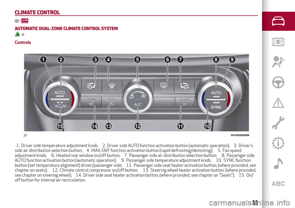
Controls
1. Driver side temperature adjustment knob; 2. Driver side AUTO function activation button (automatic operation); 3. Driver's
side air distribution selection button; 4. MAX-DEF function activation button (rapid defrosting/demisting); 5. Fan speed
adjustment knob; 6. Heated rear window on/off button; 7. Passenger side air distribution selection button; 8. Passenger side
AUTO function activation button (automatic operation); 9. Passenger side temperature adjustment knob; 10. SYNC function
button (set temperature alignment) driver/passenger side; 11. Passenger side seat heater activation button; (where provided, see
chapter on seats); 12. Climate control compressor on/off button; 13. Steering wheel heater activation button; (where provided,
see chapter on steering wheel); 14. Driver side seat heater activation button; (where provided, see chapter on "Seats"); 15. On/
off button for internal air recirculation.
3704156S0005EM
33
Page 49 of 232
1 Gearbox Information
Automatic transmission
Displays the following information
regarding the gearbox operation:
transmission operating mode (M, P, R,
N, D). In D mode, when changing gear
using the steering wheel lever (where
present), or manually M, it also show the
gear engaged with a number. In M mode,
it also shows when to shift gear up or
down by displaying an arrow.
Manual transmission
Displays the following information
regarding the gearbox operation:
the engaged gear (1, 2, 3, 4, 5, 6, N or
R) and shows when to shift gear up or
down by displaying an arrow.
2 Front, side anti-collision systems,
Cruise Control
Displays the operation the following
modes:
Forward Collision Warning (FCW);
Lane Departure Warning (LDW);
Cruise Control (CC) or Active Cruise
Control (ACC) (where provided).
For further information, see relevant
paragraphs.
3 Speed limit warning light
Shows information regarding the Speed
Limiter function.
For further information, see relevant
paragraph.4 Reconfigurable main area
Can display the following screens:
Home.
Trip A.
Trip B (can be activated/deactivated
on the Connect system).
Performance.
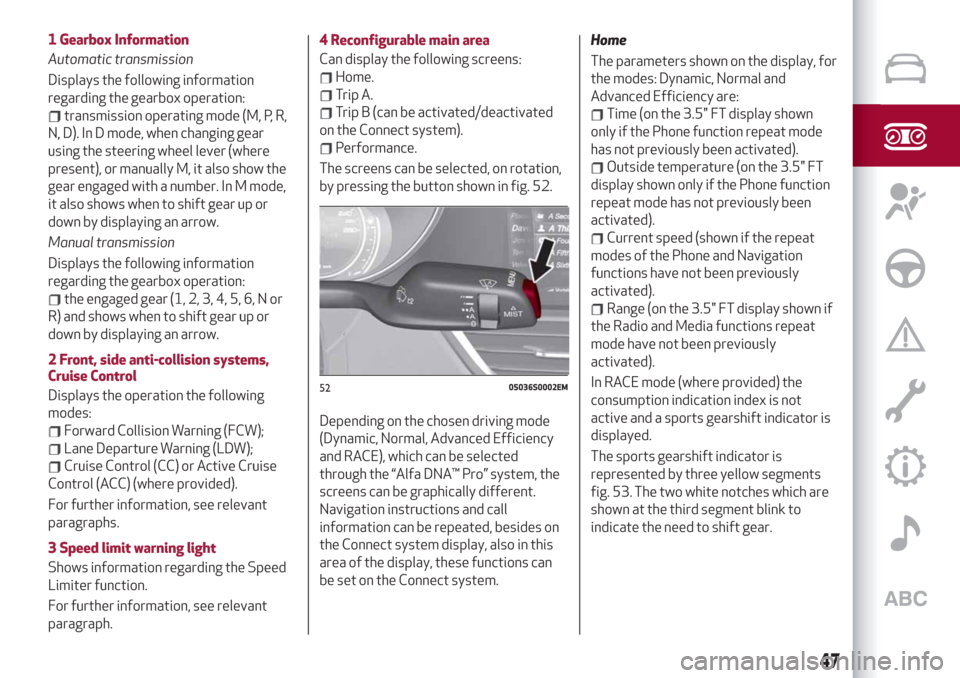
The screens can be selected, on rotation,
by pressing the button shown in fig. 52.
Depending on the chosen driving mode
(Dynamic, Normal, Advanced Efficiency
and RACE), which can be selected
through the “Alfa DNA™ Pro” system, the
screens can be graphically different.
Navigation instructions and call
information can be repeated, besides on
the Connect system display, also in this
area of the display, these functions can
be set on the Connect system.Home
The parameters shown on the display, for
the modes: Dynamic, Normal and
Advanced Efficiency are:
Time (on the 3.5" FT display shown
only if the Phone function repeat mode
has not previously been activated).
Outside temperature (on the 3.5" FT
display shown only if the Phone function
repeat mode has not previously been
activated).
Current speed (shown if the repeat
modes of the Phone and Navigation
functions have not been previously
activated).
Range (on the 3.5" FT display shown if
the Radio and Media functions repeat
mode have not been previously
activated).
In RACE mode (where provided) the
consumption indication index is not
active and a sports gearshift indicator is
displayed.
The sports gearshift indicator is
represented by three yellow segments
fig. 53. The two white notches which are
shown at the third segment blink to
indicate the need to shift gear.
5205036S0002EM
47