gas type ALFA ROMEO GIULIA 2022 Owners Manual
[x] Cancel search | Manufacturer: ALFA ROMEO, Model Year: 2022, Model line: GIULIA, Model: ALFA ROMEO GIULIA 2022Pages: 248, PDF Size: 9.71 MB
Page 14 of 248

12
ENGINE COMPARTMENT....................... 187
Checking Levels — 2.0L Engine .......... 187
Checking Levels — 2.9L Engine .........188
Engine Oil ............................................. 188
Engine Coolant ..................................... 190
Washer Fluid For Windshield/
Headlights ............................................ 190 Brake Fluid ...........................................190
Automatic Transmission Activation
System Oil ............................................ 190 Useful Advice For Extending The Life
Of Your Battery ..................................... 190 Battery ..................................................190
Pressure Washing ................................ 191
BATTERY RECHARGING......................... 191
Important Notes ...................................191
VEHICLE MAINTENANCE ....................... 192
Engine Oil ............................................. 192
Engine Oil Filter ....................................192
Engine Air Cleaner ............................... 192
Air Conditioning System
Maintenance ........................................192 Lubricating Moving Parts Of The
Bodywork ..............................................193 Windshield Wiper .................................193
Exhaust System ...................................194
Engine Cooling System ........................ 195
Braking System ....................................196
Automatic Transmission ......................196
Replacing The Battery ......................... 197
Fuses ................................................... 197
Bulb Replacement ............................... 202
TIRES ..................................................... 206
Tire Safety Information ....................... 206
Tires — General Information .............. 212
Spare Tires — If Equipped ................... 216
Wheel And Wheel Trim Care ............... 217
Tire Types ............................................. 217
Snow Traction Devices ........................ 218
Tire Rotation Recommendations........ 219
DEPARTMENT OF TRANSPORTATION
UNIFORM TIRE QUALITY GRADES ........ 219
Treadwear ............................................ 219
Traction Grades ................................... 220
Temperature Grades ........................... 220
STORING THE VEHICLE ......................... 220
BODYWORK ............................................ 221
Protection Against Atmospheric
Agents .................................................. 221 Corrosion Warranty.............................. 221
Preserving The Bodywork.................... 222
INTERIORS.............................................. 222
Seats And Fabric Parts........................ 222
Leather Seats ...................................... 223
Plastic And Coated Parts .................... 223
Alcantara Parts — If Equipped ............ 223
Genuine Leather Surfaces —
If Equipped ........................................... 223 Carbon Fiber Parts .............................. 223
TECHNICAL SPECIFICATIONS
VEHICLE IDENTIFICATION NUMBER
(VIN) ........................................................ 224
Vehicle Identification Number (VIN)
Plate ..................................................... 224
ENGINE .................................................. 224
POWER SUPPLY ..................................... 225 TRANSMISSION ..................................... 225BRAKES.................................................. 226
SUSPENSION ......................................... 226
STEERING SYSTEM ............................... 226DIMENSIONS — 2.0L ENGINE ............... 227
DIMENSIONS — 2.9L Engine ................ 228
WEIGHTS — 2.0L ENGINE ..................... 229
WEIGHTS — 2.9L ENGINE ..................... 229
FUEL REQUIREMENTS .......................... 230
Reformulated Gasoline....................... 230
Gasoline/Oxygenate Blends ............... 230
CNG And LP Fuel System
Modifications ....................................... 230 Methylcyclopentadienyl Manganese
Tricarbonyl (MMT) In Gasoline ........... 230 Materials Added To Fuel ..................... 230
Fuel System Cautions ......................... 231
FLUID CAPACITIES ................................. 231
2.0L Engine ......................................... 231
2.9L V6 Engine .................................... 232
ENGINE FLUIDS AND LUBRICANTS ...... 233
2.0L Engine ......................................... 233
2.9L Engine ......................................... 233
CHASSIS FLUIDS AND LUBRICANTS..... 234
2.0L Engine ......................................... 234
2.9L Engine ......................................... 234
PERFORMANCE — 2.0L ENGINE........... 235 PERFORMANCE — 2.9L ENGINE........... 235
22_GA_OM_EN_USC_t.book Page 12
Page 96 of 248
STARTING AND OPERATING
94
“RACE” Mode (Quadrifoglio Only)
Activation
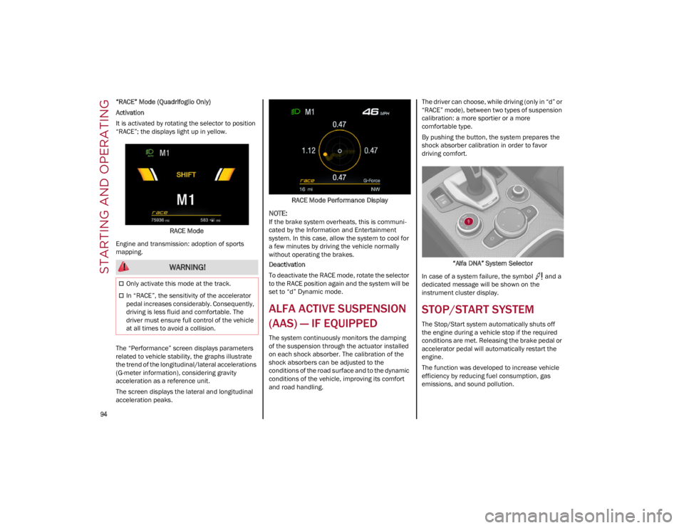
It is activated by rotating the selector to position
“RACE”; the displays light up in yellow.RACE Mode
Engine and transmission: adoption of sports
mapping.
The “Performance” screen displays parameters
related to vehicle stability, the graphs illustrate
the trend of the longitudinal/lateral accelerations
(G-meter information), considering gravity
acceleration as a reference unit.
The screen displays the lateral and longitudinal
acceleration peaks. RACE Mode Performance Display
NOTE:
If the brake system overheats, this is communi
-
cated by the Information and Entertainment
system. In this case, allow the system to cool for
a few minutes by driving the vehicle normally
without operating the brakes.
Deactivation
To deactivate the RACE mode, rotate the selector
to the RACE position again and the system will be
set to “d” Dynamic mode.
ALFA ACTIVE SUSPENSION
(AAS) — IF EQUIPPED
The system continuously monitors the damping
of the suspension through the actuator installed
on each shock absorber. The calibration of the
shock absorbers can be adjusted to the
conditions of the road surface and to the dynamic
conditions of the vehicle, improving its comfort
and road handling. The driver can choose, while driving (only in “d” or
“RACE” mode), between two types of suspension
calibration: a more sportier or a more
comfortable type.
By pushing the button, the system prepares the
shock absorber calibration in order to favor
driving comfort.
“Alfa DNA” System Selector
In case of a system failure, the symbol and a
dedicated message will be shown on the
instrument cluster display.
STOP/START SYSTEM
The Stop/Start system automatically shuts off
the engine during a vehicle stop if the required
conditions are met. Releasing the brake pedal or
accelerator pedal will automatically restart the
engine.
The function was developed to increase vehicle
efficiency by reducing fuel consumption, gas
emissions, and sound pollution.
WARNING!
Only activate this mode at the track.
In “RACE”, the sensitivity of the accelerator
pedal increases considerably. Consequently,
driving is less fluid and comfortable. The
driver must ensure full control of the vehicle
at all times to avoid a collision.
22_GA_OM_EN_USC_t.book Page 94
Page 126 of 248
STARTING AND OPERATING
124
REFUELING PROCEDURE
The fuel filler door is unlocked when the central
door locking system is unlocked. It is automat-
ically locked when the central locking system is
applied.
Opening The Fuel Filler Door
To refuel proceed as follows:
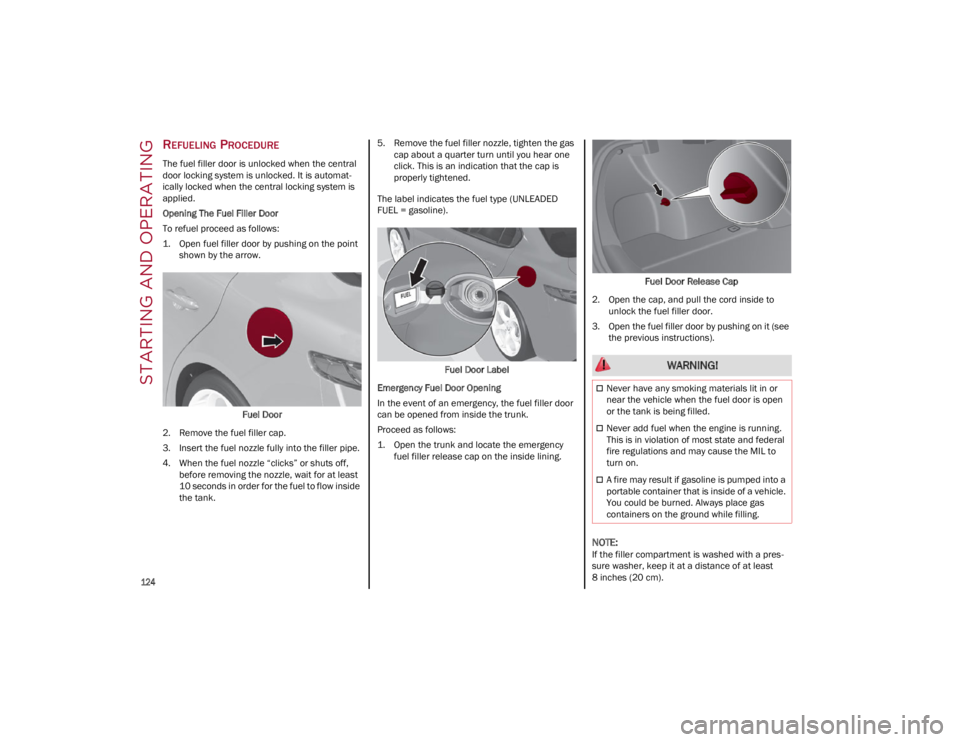
1. Open fuel filler door by pushing on the point shown by the arrow.
Fuel Door
2. Remove the fuel filler cap.
3. Insert the fuel nozzle fully into the filler pipe.
4. When the fuel nozzle “clicks” or shuts off, before removing the nozzle, wait for at least
10 seconds in order for the fuel to flow inside
the tank. 5. Remove the fuel filler nozzle, tighten the gas
cap about a quarter turn until you hear one
click. This is an indication that the cap is
properly tightened.
The label indicates the fuel type (UNLEADED
FUEL = gasoline).
Fuel Door Label
Emergency Fuel Door Opening
In the event of an emergency, the fuel filler door
can be opened from inside the trunk.
Proceed as follows:
1. Open the trunk and locate the emergency fuel filler release cap on the inside lining. Fuel Door Release Cap
2. Open the cap, and pull the cord inside to unlock the fuel filler door.
3. Open the fuel filler door by pushing on it (see the previous instructions).
NOTE:
If the filler compartment is washed with a pres -
sure washer, keep it at a distance of at least
8 inches (20 cm).
WARNING!
Never have any smoking materials lit in or
near the vehicle when the fuel door is open
or the tank is being filled.
Never add fuel when the engine is running.
This is in violation of most state and federal
fire regulations and may cause the MIL to
turn on.
A fire may result if gasoline is pumped into a
portable container that is inside of a vehicle.
You could be burned. Always place gas
containers on the ground while filling.
22_GA_OM_EN_USC_t.book Page 124
Page 153 of 248
151
Driver And Passenger Front Air Bag
Features
The Advanced Front Air Bag system has
multistage driver and front passenger air bags.
This system provides output appropriate to the
severity and type of collision as determined by the
Occupant Restraint Controller (ORC), which may
receive information from the front impact sensors
(if equipped) or other system components.
The first stage inflator is triggered immediately
during an impact that requires air bag
deployment. A low energy output is used in less severe collisions. A higher energy output is used
for more severe collisions.
This vehicle may be equipped with a driver and/
or front passenger seat belt buckle switch that
detects whether the driver or front passenger
seat belt is buckled. The seat belt buckle switch
may adjust the inflation rate of the Advanced
Front Air Bags.
This vehicle may be equipped with driver and/or
front passenger seat track position sensors that
may adjust the inflation rate of the Advanced
Front Air Bags based upon seat position.
Front Air Bag Operation
Front Air Bags are designed to provide additional
protection by supplementing the seat belts. Front
air bags are not expected to reduce the risk of
injury in rear, side, or rollover collisions. The front
air bags will not deploy in all frontal collisions,
including some that may produce substantial
vehicle damage — for example, some pole
collisions, truck underrides, and angle offset
collisions.
On the other hand, depending on the type and
location of impact, front air bags may deploy in
crashes with little vehicle front-end damage but
that produce a severe initial deceleration.
Because air bag sensors measure vehicle
deceleration over time, vehicle speed and
damage by themselves are not good indicators of
whether or not an air bag should have deployed.
Seat belts are necessary for your protection in all
collisions, and also are needed to help keep you
in position, away from an inflating air bag.
When the Occupant Restraint Controller (ORC)
detects a collision requiring the front air bags, it
signals the inflator units. A large quantity of
non-toxic gas is generated to inflate the front air
bags.
The steering wheel hub trim cover and the upper
passenger side of the instrument panel separate
and fold out of the way as the air bags inflate to
their full size. The front air bags fully inflate in less
time than it takes to blink your eyes. The front air
bags then quickly deflate while helping to restrain
the driver and front passenger. WARNING!
Being too close to the steering wheel or
instrument panel during front air bag
deployment could cause serious injury,
including death. Air bags need room to
inflate. Sit back, comfortably extending your
arms to reach the steering wheel or
instrument panel.
Never place a rear-facing child restraint in
front of an air bag. A deploying passenger
front air bag can cause death or serious
injury to a child 12 years or younger,
including a child in a rear-facing child
restraint.
Never install a rear-facing child restraint in
the front seat of a vehicle. Only use a
rear-facing child restraint in the rear seat. If
the vehicle does not have a rear seat, do not
transport a rear-facing child restraint in that
vehicle.
WARNING!
No objects should be placed over or near the
air bag on the instrument panel or steering
wheel because any such objects could cause
harm if the vehicle is in a collision severe
enough to cause the air bag to inflate.
Do not put anything on or around the air bag
covers or attempt to open them manually.
You may damage the air bags and you could
be injured because the air bags may no
longer be functional. The protective covers
for the air bag cushions are designed to open
only when the air bags are inflating.
Relying on the air bags alone could lead to
more severe injuries in a collision. The air
bags work with your seat belt to restrain you
properly. In some collisions, air bags won’t
deploy at all. Always wear your seat belts
even though you have air bags.
22_GA_OM_EN_USC_t.book Page 151
Page 156 of 248
SAFETY
154
NOTE:
Air bag covers may not be obvious in the interior
trim, but they will open during air bag deploy-
ment.
Rollover Events
Side Air Bags and seat belt pretensioners are
designed to activate in certain rollover events.
The Occupant Restraint Controller (ORC)
determines whether deployment in a particular
rollover event is appropriate, based on the
severity and type of collision. Vehicle damage by
itself is not a good indicator of whether or not
Side Air Bags and seat belt pretensioners should
have deployed.
The Side Air Bags and seat belt pretensioners will
not deploy in all rollover events. The rollover
sensing system determines if a rollover event
may be in progress and whether deployment is
appropriate. In the event the vehicle experiences
a rollover or near rollover event, and deployment is appropriate, the rollover sensing system will
deploy the side air bags and seat belt preten
-
sioners on both sides of the vehicle.
The SABICs may help reduce the risk of partial or
complete ejection of vehicle occupants through
side windows in certain rollover or side impact
events.
Air Bag System Components
NOTE:
The Occupant Restraint Controller (ORC) moni -
tors the internal circuits and interconnecting
wiring associated with electrical Air Bag System
Components listed below:
Occupant Restraint Controller (ORC)
Air Bag Warning Light
Steering Wheel and Column
Instrument Panel
Knee Impact Bolsters
Driver and Front Passenger Air Bags
Seat Belt Buckle Switch
Supplemental Side Air Bags
Supplemental Knee Air Bags
Front and Side Impact Sensors
Seat Belt Pretensioners
Seat Track Position Sensors
If A Deployment Occurs
The front air bags are designed to deflate
immediately after deployment.
NOTE:
Front and/or side air bags will not deploy in all
collisions. This does not mean something is
wrong with the air bag system. If you do have a collision which deploys the air
bags, any or all of the following may occur:
The air bag material may sometimes cause
abrasions and/or skin reddening to the
occupants as the air bags deploy and unfold.
The abrasions are similar to friction rope burns
or those you might get sliding along a carpet or
gymnasium floor. They are not caused by
contact with chemicals. They are not
permanent and normally heal quickly.
However, if you haven’t healed significantly
within a few days, or if you have any blistering,
see your doctor immediately.
As the air bags deflate, you may see some
smoke-like particles. The particles are a
normal by-product of the process that
generates the non-toxic gas used for air bag
inflation. These airborne particles may irritate
the skin, eyes, nose, or throat. If you have skin
or eye irritation, rinse the area with cool water.
For nose or throat irritation, move to fresh air.
If the irritation continues, see your doctor. If
these particles settle on your clothing, follow
the garment manufacturer’s instructions for
cleaning.
Do not drive your vehicle after the air bags have
deployed. If you are involved in another collision,
the air bags will not be in place to protect you.
WARNING!
Side Air Bags need room to inflate. Do not
lean against the door or window. Sit upright
in the center of the seat.
Being too close to the Side Air Bags during
deployment could cause you to be severely
injured or killed.
Relying on the Side Air Bags alone could lead
to more severe injuries in a collision. The
Side Air Bags work with your seat belt to
restrain you properly. In some collisions, Side
Air Bags won’t deploy at all. Always wear your
seat belt even though you have Side Air
Bags.
WARNING!
Deployed air bags and seat belt pretensioners
cannot protect you in another collision. Have
the air bags, seat belt pretensioners, and the
seat belt retractor assemblies replaced by an
authorized dealer immediately. Also, have the
Occupant Restraint Controller System serviced
as well.
22_GA_OM_EN_USC_t.book Page 154
Page 205 of 248
203
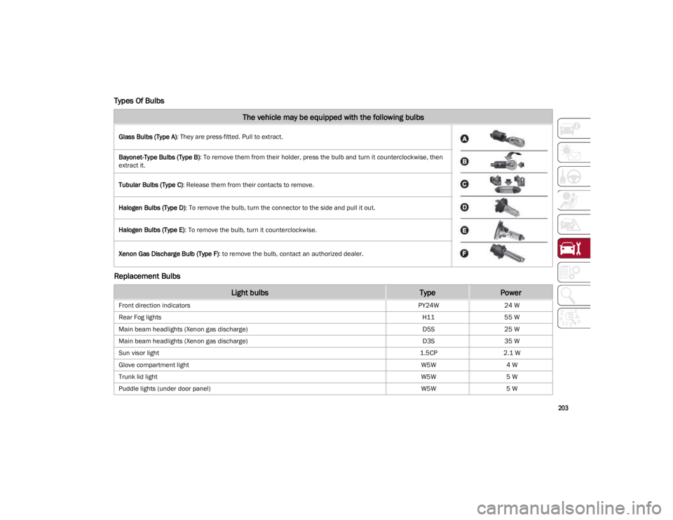
Types Of Bulbs
Replacement Bulbs
The vehicle may be equipped with the following bulbs
Glass Bulbs (Type A): They are press-fitted. Pull to extract.
Bayonet-Type Bulbs (Type B) : To remove them from their holder, press the bulb and turn it counterclockwise, then
extract it.
Tubular Bulbs (Type C) : Release them from their contacts to remove.
Halogen Bulbs (Type D) : To remove the bulb, turn the connector to the side and pull it out.
Halogen Bulbs (Type E) : To remove the bulb, turn it counterclockwise.
Xenon Gas Discharge Bulb (Type F) : to remove the bulb, contact an authorized dealer.
Light bulbsTypePower
Front direction indicators PY24W24 W
Rear Fog lights H1155 W
Main beam headlights (Xenon gas discharge) D5S25 W
Main beam headlights (Xenon gas discharge) D3S35 W
Sun visor light 1.5CP2.1 W
Glove compartment light W5W4 W
Trunk lid light W5W5 W
Puddle lights (under door panel) W5W5 W
22_GA_OM_EN_USC_t.book Page 203