steering wheel adjustment ALFA ROMEO GIULIA 2023 Owners Manual
[x] Cancel search | Manufacturer: ALFA ROMEO, Model Year: 2023, Model line: GIULIA, Model: ALFA ROMEO GIULIA 2023Pages: 248, PDF Size: 9.62 MB
Page 10 of 248
8
READ THIS CAREFULLY
Warnings And Cautions.............................. 2
Respecting The Environment .................... 2
Rollover Warning ........................................ 3
VEHICLE CHANGES /
ALTERATIONS
Accessories Purchased By The Owner ...... 4
Installing Electrical/Electronic Devices .... 4
Radio Transmitters And Mobile Phones ... 4
HOW TO USE THIS MANUAL
Operating Instructions ............................... 5
Symbols Key ............................................... 5
Symbols ...................................................... 6
Symbols Glossary .....................................14
GETTING TO KNOW YOUR
VEHICLE
KEYS..........................................................19
Key Fob .................................................. 19
ENGINE IMMOBILIZER SYSTEM ..............21
IGNITION SWITCH .....................................22
Keyless Push Button Ignition ................ 22
REMOTE START — IF EQUIPPED ..............23
How To Use Remote Start ..................... 23
To Exit Remote Start Mode ................... 23
Remote Start Comfort Systems —
If Equipped ............................................. 23
VEHICLE SECURITY
SYSTEM — IF EQUIPPED .......................... 24
To Arm The System................................ 24
To Disarm The System .......................... 24
Volumetric/Anti-Lift Protection —
If Equipped ............................................. 25
DOORS ...................................................... 25
Power Door Locks.................................. 25
Locking The Doors With A Depleted
Battery .................................................... 26 Passive Entry System ........................... 26
Automatic Door Locks — If Equipped .. 28
Child-Protection Door Lock
System — Rear Doors ............................ 28
STEERING WHEEL.................................... 29
Manual Tilt/Telescoping Steering
Column ................................................... 29 Heated Steering Wheel —
If Equipped ............................................. 30
DRIVER MEMORY SETTINGS —
IF EQUIPPED ............................................ 30
Programming The Memory Feature ..... 30
Memory Position Recall ........................ 31
SEATS ....................................................... 31
Sparco Racing Seats
(Quadrifoglio Vehicles) — If Equipped .. 31 Manual Adjustment (Rear Seats) ......... 32
Power Adjustment (Front Seats)........... 34
Heated Seats — If Equipped ................ 35
Head Restraints .................................... 36
MIRRORS ..................................................37
Automatic Dimming Mirror ....................37
Vanity Mirror ...........................................38
Outside Power Mirrors ...........................38
Power Folding Outside Mirrors ..............39
Outside Automatic Dimming Mirrors —
If Equipped .............................................39 Heated Mirrors ......................................39
UNIVERSAL GARAGE DOOR OPENER
(HOMELINK®)
S ...................................39
Before You Begin Programming
HomeLink® ............................................40 Erasing All The HomeLink® Channels ..40
Identifying Whether You Have A
Rolling Code Or Non-Rolling Code
Device .....................................................40 Programming HomeLink® To A
Garage Door Opener ..............................40 Programming HomeLink® To A
Miscellaneous Device ............................ 41 Reprogramming A Single HomeLink®
Button .....................................................41 Canadian/Gate Operator
Programming .......................................... 41 Security ...................................................42
Troubleshooting Tips..............................42
23_GA_OM_EN_USC_t.book Page 8
Page 31 of 248
29
NOTE:
Always use this device when carrying children.
After engaging the child lock on both rear doors,
check for effective engagement by trying to open
a door with the internal handle. Once the
Child-Protection Door Lock system is engaged, it
is impossible to open the doors from inside the
vehicle. Before getting out of the vehicle, be sure
to check that there is no one left inside.
STEERING WHEEL
MANUAL TILT/TELESCOPING STEERING
C
OLUMN
This feature allows you to tilt the steering column
upward or downward. It also allows you to
lengthen or shorten the steering column. The tilt/
telescoping lever is located below the steering
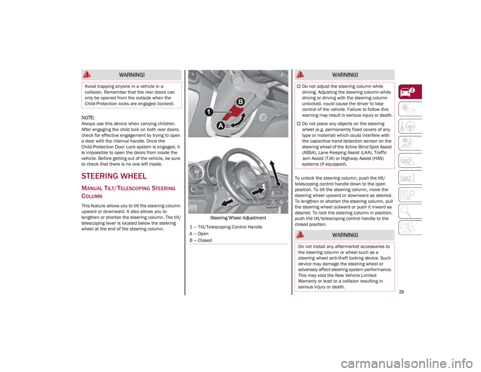
wheel at the end of the steering column. Steering Wheel AdjustmentTo unlock the steering column, push the tilt/
telescoping control handle down to the open
position. To tilt the steering column, move the
steering wheel upward or downward as desired.
To lengthen or shorten the steering column, pull
the steering wheel outward or push it inward as
desired. To lock the steering column in position,
push the tilt/telescoping control handle to the
closed position.
WARNING!
Avoid trapping anyone in a vehicle in a
collision. Remember that the rear doors can
only be opened from the outside when the
Child-Protection locks are engaged (locked).
1 — Tilt/Telescoping Control Handle
A — Open
B — Closed
WARNING!
Do not adjust the steering column while
driving. Adjusting the steering column while
driving or driving with the steering column
unlocked, could cause the driver to lose
control of the vehicle. Failure to follow this
warning may result in serious injury or death.
Do not place any objects on the steering
wheel (e.g. permanently fixed covers of any
type or material) which could interfere with
the capacitive hand detection sensor on the
steering wheel of the Active Blind Spot Assist
(ABSA), Lane Keeping Assist (LKA), Traffic
Jam Assist (TJA) or Highway Assist (HAS)
systems (if equipped).
WARNING!
Do not install any aftermarket accessories to
the steering column or wheel such as a
steering wheel anti-theft locking device. Such
device may damage the steering wheel or
adversely affect steering system performance.
This may void the New Vehicle Limited
Warranty or lead to a collision resulting in
serious injury or death.
23_GA_OM_EN_USC_t.book Page 29
Page 32 of 248
GETTING TO KNOW YOUR VEHICLE
30
HEATED STEERING WHEEL — IF EQUIPPED
The steering wheel contains a heating
element that helps warm your hands in
cold weather. The heated steering
wheel has only one temperature setting.
The heated steering wheel may not turn on when
it is already warm.
NOTE:
Quadrifoglio vehicles equipped with Sparco
Racing Seats will not be equipped with the
heated steering wheel feature.
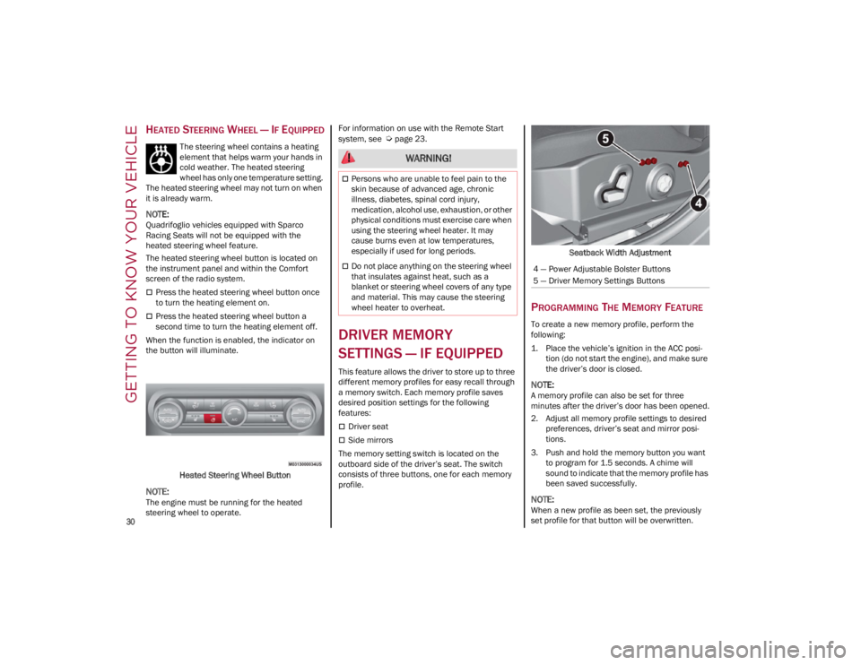
The heated steering wheel button is located on
the instrument panel and within the Comfort
screen of the radio system.
Press the heated steering wheel button once
to turn the heating element on.
Press the heated steering wheel button a
second time to turn the heating element off.
When the function is enabled, the indicator on
the button will illuminate.
Heated Steering Wheel Button
NOTE:
The engine must be running for the heated
steering wheel to operate. For information on use with the Remote Start
system, see
Ú
page 23.
DRIVER MEMORY
SETTINGS — IF EQUIPPED
This feature allows the driver to store up to three
different memory profiles for easy recall through
a memory switch. Each memory profile saves
desired position settings for the following
features:
Driver seat
Side mirrors
The memory setting switch is located on the
outboard side of the driver’s seat. The switch
consists of three buttons, one for each memory
profile. Seatback Width Adjustment
PROGRAMMING THE MEMORY FEATURE
To create a new memory profile, perform the
following:
1. Place the vehicle’s ignition in the ACC posi
-
tion (do not start the engine), and make sure
the driver’s door is closed.
NOTE:
A memory profile can also be set for three
minutes after the driver’s door has been opened.
2. Adjust all memory profile settings to desired preferences, driver’s seat and mirror posi -
tions.
3. Push and hold the memory button you want to program for 1.5 seconds. A chime will
sound to indicate that the memory profile has
been saved successfully.
NOTE:
When a new profile as been set, the previously
set profile for that button will be overwritten.
WARNING!
Persons who are unable to feel pain to the
skin because of advanced age, chronic
illness, diabetes, spinal cord injury,
medication, alcohol use, exhaustion, or other
physical conditions must exercise care when
using the steering wheel heater. It may
cause burns even at low temperatures,
especially if used for long periods.
Do not place anything on the steering wheel
that insulates against heat, such as a
blanket or steering wheel covers of any type
and material. This may cause the steering
wheel heater to overheat.4 — Power Adjustable Bolster Buttons
5 — Driver Memory Settings Buttons
23_GA_OM_EN_USC_t.book Page 30
Page 51 of 248
49
AUTOMATIC DUAL-ZONE CLIMATE CONTROL SYSTEM
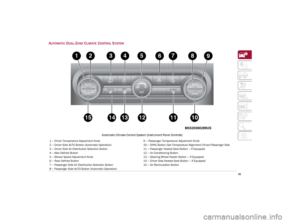
Automatic Climate Control System (Instrument Panel Controls)
1 — Driver Temperature Adjustment Knob9 — Passenger Temperature Adjustment Knob
2 — Driver Side AUTO Button (Automatic Operation) 10 — SYNC Button (Set Temperature Alignment) Driver/Passenger Side
3 — Driver Side Air Distribution Selection Button 11 — Passenger Heated Seat Button — If Equipped
4 — Max Defrost Button 12 — Air Conditioning Button
5 — Blower Speed Adjustment Knob 13 — Steering Wheel Heater Button — If Equipped
6 — Rear Defrost Button 14 — Driver Side Heated Seat Button — If Equipped
7 — Passenger Side Air Distribution Selection Button 15 — Air Recirculation Button
8 — Passenger Side AUTO Button (Automatic Operation)
23_GA_OM_EN_USC_t.book Page 49
Page 116 of 248
STARTING AND OPERATING
114
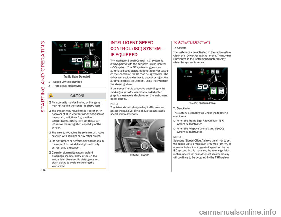
Traffic Signs Detected
INTELLIGENT SPEED
CONTROL (ISC) SYSTEM —
IF EQUIPPED
The Intelligent Speed Control (ISC) system is
always paired with the Adaptive Cruise Control
(ACC) system. The ISC system suggests an
automatic speed adjustment to the driver based
on the speed limit for the road being traveled. The
driver can decide whether to accept or reject the
automatic speed adjustment, using the switch on
the steering wheel.
If the speed limit is exceeded according to the
road signs or traffic conditions, a dedicated
graphic message is displayed on the instrument
panel display.
NOTE:
The driver should always obey traffic laws and
speed limits. Never drive above the applicable
speed limit restrictions.RES/SET Switch
TO ACTIVATE/DEACTIVATE
To Activate
The system can be activated in the radio system
within the “Driver Assistance” menu. The symbol
illuminates in the instrument cluster display
when the system is active.1 — ISC System Active
To Deactivate
The system is deactivated under the following
conditions:
When the Traffic Sign Recognition (TSR)
system is deactivated
When the Adaptive Cruise Control (ACC)
system is deactivated
NOTE:
Selecting “Speed Offset” allows the driver to set
the speed up to a maximum of 6 mph (10 km/h)
above or below the suggested speed set by the
ISC system. In this instance, the road sign infor -
mation shown in the instrument cluster display
will continue to be detected by the TSR system.
1 — Speed Limit Recognized
2 — Traffic Sign Recognized
CAUTION!
Functionality may be limited or the system
may not work if the sensor is obstructed.
The system may have limited operation or
not work at all in weather conditions such as
heavy rain, hail, thick fog, and low
temperatures. Strong light contrasts can
influence the recognition capability of the
sensor.
The area surrounding the sensor must not be
covered with stickers or any other object.
Do not tamper or perform any operations in
the area of the windshield glass directly
surrounding the sensor.
Clean foreign matters such as bird
droppings, insects, snow or ice on the
windshield. Use specific detergents and
clean cloths to avoid scratching the
windshield.
23_GA_OM_EN_USC_t.book Page 114
Page 144 of 248
SAFETY
142
TIRE PRESSURE MONITORING SYSTEM
(TPMS)
The vehicle is equipped with a TPMS that sends
the inflation pressure information of each tire to
the control unit, and will signal the driver in the
event of insufficient tire pressure. The TPMS uses wireless technology with wheel
rim mounted electronic sensors to monitor tire
pressure levels. Sensors, mounted to each wheel
as part of the valve stem, transmit tire pressure
readings to the receiver module.
Tire pressure will vary with temperature by
approximately 1 psi (7 kPa) for every 12°F
(6.5°C). This means that when the outside
temperature decreases, the tire pressure will
also decrease. Tire pressure should always be set
based on cold inflation tire pressure. This is
defined as the tire pressure after the vehicle has
not been driven for at least three hours, or driven
less than 1 mile (1.6 km) after a three hour
period. The cold tire inflation pressure must not
exceed the maximum inflation pressure molded
into the tire sidewall. The tire pressure will also
increase as the vehicle is driven. This is normal,
and there should be no adjustment for this
increased pressure. See
Ú
page 206 for
information on how to properly inflate the
vehicle’s tires.
The TPMS will signal the driver if pressure falls
below the warning limit for any reason, including
the effects of low temperature and normal loss of
pressure from the tire.
The TPMS will stop indicating insufficient tire
pressure when pressure is equal to or greater
than the prescribed cold inflation level.
Therefore, if insufficient tire pressure is indicated
by the ( ) warning light displaying in the
instrument cluster, increase the inflation
pressure up to the prescribed cold inflation value. The system will automatically update, and the
Tire Pressure Monitoring System Warning Light
will turn off once the system receives the updated
tire pressures. The vehicle may need to be driven
for up to 20 minutes above 15 mph (24 km/h) in
order for the TPMS to receive this information.
NOTE:
The TPMS cannot indicate sudden tire pressure
drops (e.g. if a tire bursts). In this case, proceed
with caution and avoid abrupt steering.
Operating Example
For example, your vehicle may have a
recommended cold (parked for more than three
hours) placard pressure of 33 psi (227 kPa). If
the ambient temperature is 68°F (20°C), and the
measured tire pressure is 28 psi (193 kPa), a
temperature drop to 20°F (-7°C) will decrease
the tire pressure to approximately 24 psi
(165 kPa). This tire pressure is low enough to turn
on the Tire Pressure Monitoring System Warning
Light. Driving the vehicle may cause the tire
pressure to rise to approximately 28 psi
(193 kPa), but the Tire Pressure Monitoring
System Warning Light will still be on. In this
situation, the Tire Pressure Monitoring System
Warning Light will turn off only after the tires are
inflated to the vehicle’s recommended cold
placard pressure value.
WARNING!
The system has not been designed to
prevent impacts and cannot detect possible
conditions leading to an accident in
advance. Failure to take into account this
warning may lead to serious or fatal injuries.
The system may activate, assessing the
trajectory of the vehicle, for the presence of
reflecting metal objects different from other
vehicles, such as safety barriers, road signs,
barriers before parking lots, tollgates, level
crossings, gates, railways, objects near road
constructions sites or higher than the vehicle
(e.g. a fly-over). In the same way, the system
may intervene inside multi-story parking lots
or tunnels, or due to a glare on the road
surface. These possible activations are a
consequence of the real driving scenario
coverage by the system and must not be
regarded as faults.
The system has been designed for road use
only. If the vehicle is driven on a track, the
system must be deactivated to avoid
unnecessary warnings. Automatic deacti
-
vation is signaled by the dedicated warning
light/symbol switching on in the instrument
panel
Ú
page 70.
23_GA_OM_EN_USC_t.book Page 142
Page 245 of 248

243
Rear Cross Path .........................................132
Reformulated Gasoline .............................. 230
Refueling Procedure ..................................124
Refueling The Vehicle ................................ 124
Refuelling.................................................... 231
Reminder, Seat Belt ...................................145
Remote ControlStarting System........................................ 23
Remote Keyless Entry .................................. 19
Remote Starting Exit Remote Start Mode .......................... 23
Remote Starting System ....................... 23, 81
Remote Trunk Release ................................ 61
Replacement Bulbs..................202, 203, 204
Replacement Tires ..................................... 215
Reporting Safety Defects ...........................238
Restraints, Child .........................................158
Rims And Tires ...........................................206
Roll Over Warning........................................... 3
S
Safety Checks Inside Vehicle ....................167
Safety Checks Outside Vehicle.................. 168
Safety Defects, Reporting ..........................238
Safety Information, Tire .............................206
Safety Tips ..................................................166
Safety, Exhaust Gas ...................................168
Saving Fuel .................................................126
Scheduled Servicing ..................................182
Scheduled Servicing Program (2.0 T4
MAir Engine Versions) ................................ 183
Scheduled Servicing Program (2.9 V6
Gasoline Engine Versions) ......................... 185
Seat Belt Reminder ...................................... 71 Seat Belts.......................................... 144, 167
Child Restraints ..................................... 158
Energy Management Feature ............... 148
Front Seat ..................................... 144, 145
Inspection .............................................. 167
Lap/Shoulder Belt Untwisting .............. 147
Lap/Shoulder Belts ............................... 145
Pregnant Women................................... 148
Pretensioners ........................................ 148
Rear Seat ............................................... 145
Reminder ............................................... 145
Seat Belt Pretensioner .......................... 148
Untwisting Procedure ............................ 147
Seats ...................................................... 31, 34 Adjustment ........................................ 31, 34
Head Restraints .......................................36
Heated ...................................................... 35
Power ........................................................34
Security Alarm............................................... 24
Service Assistance .................................... 236
Service Contract ........................................ 237
Service Manuals ........................................ 238
Servicing Procedures ................................ 192
Shoulder Belts ........................................... 145
Signals, Turn ........................................74, 168
Snow Chains .............................................. 218
Snow Tires.................................................. 218
Spare Tires ................................................. 216
Speed Control Accel/Decel ..............................................99
Accel/Decel (ACC Only) ......................... 102Cancel .......................................................99
Distance Setting (ACC Only).................. 103
Resume .....................................................99
Set .............................................................98 Speed Control (Cruise Control) ................... 97
Speed Limiting System ................................ 96
Starting Button....................................................... 22Cold Weather ........................................... 82
Remote ..................................................... 23
Starting The Engine ..................................... 81
Steering Tilt Column ............................................... 29
Wheel, Heated ......................................... 30
Wheel, Tilt ................................................ 29
Steering System ......................................... 226
Stop/Start System ....................................... 94
Storage Console .................................................... 55
Glove Compartment ................................ 55
Suggestions For Driving............................. 126
Sun Roof .................................................58, 60
Sun Visor ...................................................... 38
Supplemental Restraint System –
Air Bag ........................................................ 150
Suspension ................................................ 226
Symbols ........................................................... 6
System, Remote Starting ............................ 23
T
Tie Down Hooks, Cargo ............................... 62
Tire And Loading Information Placard ...... 209
Tire Markings ............................................. 206
Tire Safety Information .............................. 206
Tire Service Kit ........................................... 171
23_GA_OM_EN_USC_t.book Page 243