warning light ALFA ROMEO GIULIA 2023 Owners Manual
[x] Cancel search | Manufacturer: ALFA ROMEO, Model Year: 2023, Model line: GIULIA, Model: ALFA ROMEO GIULIA 2023Pages: 248, PDF Size: 9.62 MB
Page 11 of 248
9
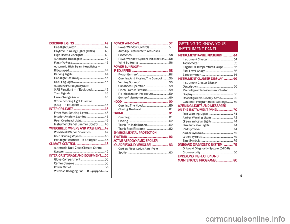
EXTERIOR LIGHTS ....................................42
Headlight Switch .................................... 42
Daytime Running Lights (DRLs) ............ 43
High Beam Headlights ........................... 43
Automatic Headlights ........................... 43
Flash-To-Pass ......................................... 43
Automatic High Beam Headlights —
If Equipped ............................................. 44 Parking Lights ........................................ 44
Headlight Off Delay ................................ 44
Rear Fog Light ........................................ 44
Adaptive Frontlight System
(AFS Function) — If Equipped ................ 45 Turn Signals ........................................... 45
Lane Change Assist ............................... 45
Static Bending Light Function
(SBL) — If Equipped ............................... 45
INTERIOR LIGHTS .....................................45
Front Map Reading Lights ..................... 45
Interior Ambient Lighting ....................... 46
Rear Overhead Light .............................. 46
Instrument Panel Dimmer Control ....... 46
WINDSHIELD WIPERS AND WASHERS....47
Windshield Wiper Operation ................. 47
Rain Sensing Wipers.............................. 48
Headlight Washers — If Equipped......... 48
CLIMATE CONTROL .................................48
Automatic Dual-Zone Climate Control
System ................................................... 49
INTERIOR STORAGE AND EQUIPMENT....55
Glove Compartment .............................. 55
Center Console ...................................... 55
Power Outlet........................................... 56
Wireless Charging Pad — If Equipped... 57
POWER WINDOWS................................... 57
Power Window Controls .........................57
Auto-Up Feature With Anti-Pinch
Protection ............................................... 58 Power Window System Initialization .....58
Wind Buffeting .......................................58
POWER SUNROOF —
IF EQUIPPED ............................................ 58
Power Sunroof ........................................ 58
Opening And Closing The Sunroof ........59
Venting Sunroof......................................59
Sunshade Operation ..............................59
Pinch Protect Feature ............................59
Re-Initialization Procedure ....................59
Sunroof Maintenance ............................60
HOOD ...................................................... 60
Opening The Hood ................................. 60
Closing The Hood ...................................61
TRUNK ...................................................... 61
Opening...................................................61
Closing ....................................................62
Trunk Re-Initialization ............................62
Trunk Specifications .............................62
ENVIRONMENTAL PROTECTION
SYSTEMS ................................................. 63
ACTIVE AERODYNAMIC SPOILER
(QUADRIFOGLIO VEHICLES) .................... 63
Carbon Fiber Active Aero Front
Spoiler .....................................................63
GETTING TO KNOW YOUR
INSTRUMENT PANEL
INSTRUMENT PANEL FEATURES ............ 64
Instrument Cluster ................................ 64
Tachometer............................................ 65
Engine Oil Temperature Gauge ............ 65
Fuel Level Gauge ................................... 66
Speedometer ......................................... 66
INSTRUMENT CLUSTER DISPLAY ........... 66
Instrument Cluster Display
Description ............................................. 66 Reconfigurable Instrument Cluster
Display .................................................... 66 Reconfigurable Display Items ............... 66
Customer Programmable Settings ....... 69
WARNING LIGHTS AND MESSAGES
ON THE INSTRUMENT PANEL ................. 70
Red Warning Lights ............................... 71
Amber Warning Lights ........................... 72
Green Indicator Lights........................... 74
Blue Indicator Lights ............................. 74
Red Symbols .......................................... 74
Amber Symbols ...................................... 76
Green Symbols ...................................... 79
Blue Symbols ......................................... 79
ONBOARD DIAGNOSTIC SYSTEM ........... 79
Onboard Diagnostic System (OBD II)
Cybersecurity ......................................... 80
EMISSIONS INSPECTION AND
MAINTENANCE PROGRAMS .................... 80
23_GA_OM_EN_USC_t.book Page 9
Page 16 of 248
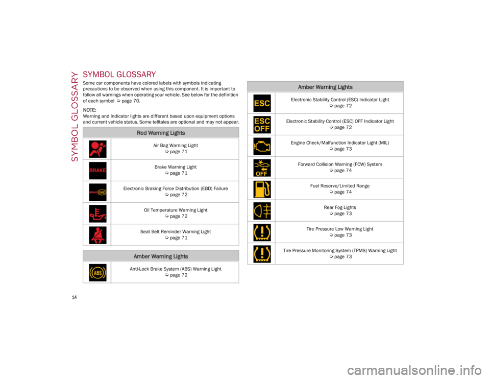
SYMBOL GLOSSARY
14
SYMBOL GLOSSARY
Some car components have colored labels with symbols indicating
precautions to be observed when using this component. It is important to
follow all warnings when operating your vehicle. See below for the definition
of each symbol
Ú
page 70.
NOTE:
Warning and Indicator lights are different based upon equipment options
and current vehicle status. Some telltales are optional and may not appear.
Red Warning Lights
Air Bag Warning Light
Ú
page 71
Brake Warning Light
Ú
page 71
Electronic Braking Force Distribution (EBD) Failure
Ú
page 72
Oil Temperature Warning Light
Ú
page 72
Seat Belt Reminder Warning Light
Ú
page 71
Amber Warning Lights
Anti-Lock Brake System (ABS) Warning Light
Ú
page 72
Electronic Stability Control (ESC) Indicator Light
Ú
page 72
Electronic Stability Control (ESC) OFF Indicator Light
Ú
page 72
Engine Check/Malfunction Indicator Light (MIL)
Ú
page 73
Forward Collision Warning (FCW) System
Ú
page 74
Fuel Reserve/Limited Range
Ú
page 74
Rear Fog Lights
Ú
page 73
Tire Pressure Low Warning Light
Ú
page 73
Tire Pressure Monitoring System (TPMS) Warning Light
Ú
page 73
Amber Warning Lights
23_GA_OM_EN_USC_t.book Page 14
Page 17 of 248
15
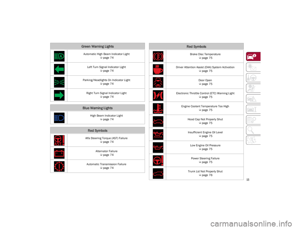
Green Warning Lights
Automatic High Beam Indicator Light
Ú
page 74
Left Turn Signal Indicator Light
Ú
page 74
Parking/Headlights On Indicator Light
Ú
page 74
Right Turn Signal Indicator Light
Ú
page 74
Blue Warning Lights
High Beam Indicator Light
Ú
page 74
Red Symbols
Alfa Steering Torque (AST) Failure
Ú
page 74
Alternator Failure
Ú
page 74
Automatic Transmission Failure
Ú
page 74
Brake Disc Temperature
Ú
page 75
Driver Attention Assist (DAA) System Activation
Ú
page 75
Door Open
Ú
page 75
Electronic Throttle Control (ETC) Warning Light
Ú
page 75
Engine Coolant Temperature Too High
Ú
page 75
Hood Cap Not Properly Shut
Ú
page 75
Insufficient Engine Oil Level
Ú
page 75
Low Engine Oil Pressure
Ú
page 75
Power Steering Failure
Ú
page 75
Trunk Lid Not Properly Shut
Ú
page 76
Red Symbols
23_GA_OM_EN_USC_t.book Page 15
Page 18 of 248
SYMBOL GLOSSARY
16
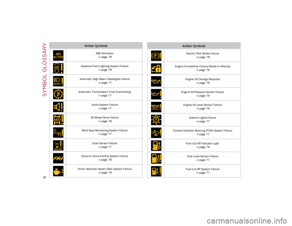
Amber Symbols
ABS Activation
Ú
page 78
Adaptive Front Lighting System Failure
Ú
page 78
Automatic High Beam Headlights Failure
Ú
page 77
Automatic Transmission Fluid Overheating
Ú
page 77
Audio System Failure
Ú
page 77
All Wheel Drive Failure
Ú
page 78
Blind Spot Monitoring System Failure
Ú
page 77
Dusk Sensor Failure
Ú
page 77
Dynamic Drive Control System Failure
Ú
page 78
Driver Attention Assist (DAA) System Failure
Ú
page 79
Electric Park Brake Failure
Ú
page 78
Engine Immobilizer Failure/Break-In Attempt
Ú
page 76
Engine Oil Change Required
Ú
page 76
Engine Oil Pressure Sensor Failure
Ú
page 76
Engine Oil Level Sensor Failure
Ú
page 76
Exterior Lights Failure
Ú
page 77
Forward Collision Warning (FCW) System Failure
Ú
page 77
Fuel Cut-Off Indicator Light
Ú
page 76
Fuel Level Sensor Failure
Ú
page 77
Fuel Cut-Off System Failure
Ú
page 77
Amber Symbols
23_GA_OM_EN_USC_t.book Page 16
Page 19 of 248
17
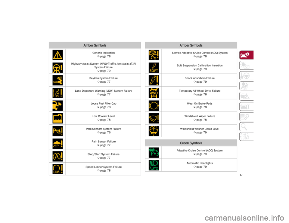
Generic Indication
Ú
page 78
Highway Assist System (HAS)/Traffic Jam Assist (TJA) System Failure
Ú
page 79
Keyless System Failure
Ú
page 77
Lane Departure Warning (LDW) System Failure
Ú
page 77
Loose Fuel Filler Cap
Ú
page 78
Low Coolant Level
Ú
page 78
Park Sensors System Failure
Ú
page 76
Rain Sensor Failure
Ú
page 77
Stop/Start System Failure
Ú
page 77
Speed Limiter System Failure
Ú
page 78
Amber Symbols
Service Adaptive Cruise Control (ACC) System
Ú
page 78
Soft Suspension Calibration Insertion
Ú
page 79
Shock Absorbers Failure
Ú
page 79
Temporary All Wheel Drive Failure
Ú
page 78
Wear On Brake Pads
Ú
page 78
Windshield Wiper Failure
Ú
page 78
Windshield Washer Liquid Level
Ú
page 79
Green Symbols
Adaptive Cruise Control (ACC) System
Ú
page 79
Automatic Headlights
Ú
page 79
Amber Symbols
23_GA_OM_EN_USC_t.book Page 17
Page 23 of 248
21
Proceed in reverse order to reassemble the key
fob.
Programming And Requesting Additional
Key Fobs
Programming the key fob may be performed by an
authorized dealer.
NOTE:
Once a key fob is programmed to a vehicle, it
cannot be repurposed and reprogrammed to
another vehicle.
Only key fobs that are programmed to the
vehicle electronics can be used to start and
operate the vehicle.Duplication of key fobs may be performed at an
authorized dealer. This procedure consists of
programming a blank key fob to the vehicle
electronics. A blank key fob is one that has never
been programmed.
NOTE:
When having the Engine Immobilizer system
serviced, bring all vehicle keys with you to an
authorized dealer.
Keys must be ordered to the correct key cut to
match the vehicle locks.
For Quadrifoglio models, if you need a
replacement key fob, contact an authorized
dealer.
ENGINE IMMOBILIZER
SYSTEM
The Engine Immobilizer system prevents
unauthorized vehicle operation by disabling the
engine. The system does not need to be armed or
activated. Operation is automatic, regardless of
whether the vehicle is locked or unlocked.
The system uses a key fob, keyless push button
ignition and a Radio Frequency (RF) receiver to
prevent unauthorized vehicle operation.
Therefore, only key fobs that are programmed to the vehicle can be used to start and operate the
vehicle. The system will shut the engine off in two
seconds if an invalid key fob is used to start the
engine.
After placing the ignition switch in the ON/RUN
position, the Vehicle Security Light will turn on for
three seconds for a bulb check. If the light
remains on after the bulb check, it indicates that
there is a problem with the electronics. In
addition, if the light begins to flash after the bulb
check, it indicates that someone used an invalid
key fob to start the engine. Either of these
conditions will result in the engine being shut off
after two seconds.
If the Vehicle Security Light turns on during
normal vehicle operation (vehicle running for
longer than 10 seconds), it indicates that there is
a fault in the electronics. Should this occur, have
the vehicle serviced as soon as possible by an
authorized dealer.
All of the key fobs provided with your new vehicle
have been programmed to the vehicle
electronics.
NOTE:
A key fob that has not been programmed is also
considered an invalid key
Ú
page 239.
WARNING!
The integrated key fob contains a coin cell
battery. Do not ingest the battery; there is a
chemical burn hazard. If the coin cell battery
is swallowed, it can cause severe internal
burns in just two hours and can lead to
death.
If you think a battery may have been
swallowed or placed inside any part of the
body, seek immediate medical attention.
Keep new and used batteries away from
children. If the battery compartment does
not close securely, stop using the product
and keep it away from children.
CAUTION!
The battery replacement operation must be done
with care, in order not to damage the key fob.
WARNING!
Always remove the key fobs from the vehicle
and lock all doors when leaving the vehicle
unattended.
Always remember to place the ignition in the
OFF position.
CAUTION!
The Engine Immobilizer system is not
compatible with some aftermarket Remote
Start systems. Use of these systems may
result in vehicle starting problems and loss of
security protection.
23_GA_OM_EN_USC_t.book Page 21
Page 25 of 248
23
REMOTE START —
IF EQUIPPED
This system uses the key fob to start the
engine conveniently from outside the
vehicle while still maintaining security.
NOTE:
Obstructions between the vehicle and key fob
may reduce this range
Ú
page 239.
HOW TO USE REMOTE START
Push the Remote Start button on the key fob
twice within five seconds. The vehicle doors will
lock, the turn signals will flash twice, and the horn
will chirp twice. Pushing the Remote Start button
a third time shuts the engine off.
NOTE:
With Remote Start, the engine will only run for
15 minutes.
Remote Start can only be used twice.
If an engine fault is present or fuel level is low,
the vehicle will start and then shut down in 10
seconds.
The park lamps will turn on and remain on
during Remote Start mode.
For security, power window operation is
disabled when the vehicle is in the Remote
Start mode.
The ignition must be placed in the ACC position
before the Remote Start sequence can be
repeated for a third cycle.
All of the following conditions must be met before
the engine will remote start:
Gear selector in PARK
Doors closed
Hood closed
Trunk closed
Hazard switch off
Brake switch inactive (brake pedal not
pressed)
Battery at an acceptable charge level
Panic button not pushed
System not disabled from previous Remote
Start event
Vehicle Security system indicator flashing
Ignition in OFF position
Fuel level meets minimum requirement
Vehicle Security system is not signaling an
intrusion
Malfunction Indicator Light (MIL) is not
illuminated
TO EXIT REMOTE START MODE
To drive the vehicle after starting the Remote
Start system, either push and release the unlock
button on the key fob to unlock the doors, or
unlock the vehicle using Passive Entry via the
door handles, and disarm the Vehicle Security
system (if equipped). Then, prior to the end of the
15 minute cycle, push and release the START/
STOP ignition button while pressing the brake
pedal.
The Remote Start system will turn the engine off
with another push and release of the Remote
Start button on the key fob, or if the engine is
allowed to run for the entire 15 minute cycle.
REMOTE START COMFORT SYSTEMS —
I
F EQUIPPED
When Remote Start is activated, the heated
steering wheel and front heated seat features will
automatically activate when ambient
temperature is less than 39°F (4°C). These
features will stay on through the duration of
Remote Start.
NOTE:
This feature can be activated through the radio
system. Refer to the Information and Entertain -
ment System Owner’s Manual Supplement for
further information.
WARNING!
Do not start or run an engine in a closed
garage or confined area. Exhaust gas
contains Carbon Monoxide (CO) which is
odorless and colorless. Carbon Monoxide is
poisonous and can cause serious injury or
death when inhaled.
Keep key fobs away from children. Operation
of the Remote Start system, windows, door
locks or other controls could cause serious
injury or death.
23_GA_OM_EN_USC_t.book Page 23
Page 27 of 248
25
(Continued)
VOLUMETRIC/ANTI-LIFT PROTECTION —
I
F EQUIPPED
To ensure the correct operation of the
Volumetric/Anti-Lift Protection system,
completely close the side windows.
To disable the function, push the Volumetric/
Anti-Lift Protection button before activating the
alarm.
When the function is disabled, the light on the
Volumetric/Anti-Lift Protection button flashes for
several seconds.
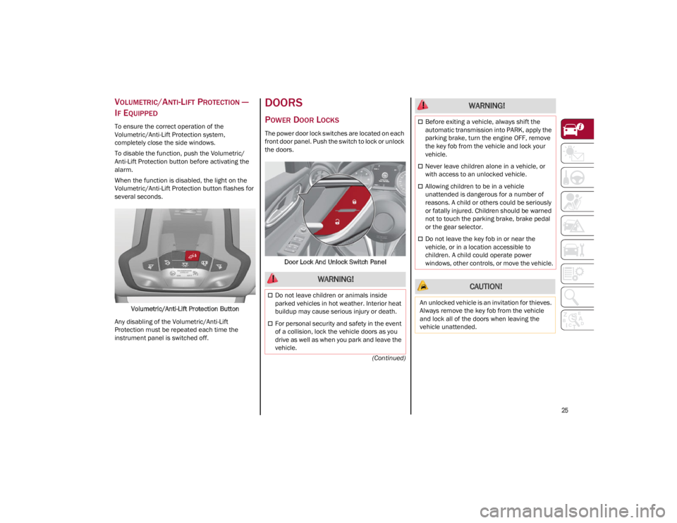
Volumetric/Anti-Lift Protection Button
Any disabling of the Volumetric/Anti-Lift
Protection must be repeated each time the
instrument panel is switched off.
DOORS
POWER DOOR LOCKS
The power door lock switches are located on each
front door panel. Push the switch to lock or unlock
the doors.
Door Lock And Unlock Switch Panel
WARNING!
Do not leave children or animals inside
parked vehicles in hot weather. Interior heat
buildup may cause serious injury or death.
For personal security and safety in the event
of a collision, lock the vehicle doors as you
drive as well as when you park and leave the
vehicle.
Before exiting a vehicle, always shift the
automatic transmission into PARK, apply the
parking brake, turn the engine OFF, remove
the key fob from the vehicle and lock your
vehicle.
Never leave children alone in a vehicle, or
with access to an unlocked vehicle.
Allowing children to be in a vehicle
unattended is dangerous for a number of
reasons. A child or others could be seriously
or fatally injured. Children should be warned
not to touch the parking brake, brake pedal
or the gear selector.
Do not leave the key fob in or near the
vehicle, or in a location accessible to
children. A child could operate power
windows, other controls, or move the vehicle.
CAUTION!
An unlocked vehicle is an invitation for thieves.
Always remove the key fob from the vehicle
and lock all of the doors when leaving the
vehicle unattended.
WARNING!
23_GA_OM_EN_USC_t.book Page 25
Page 34 of 248
GETTING TO KNOW YOUR VEHICLE
32
MANUAL ADJUSTMENT (REAR SEATS)
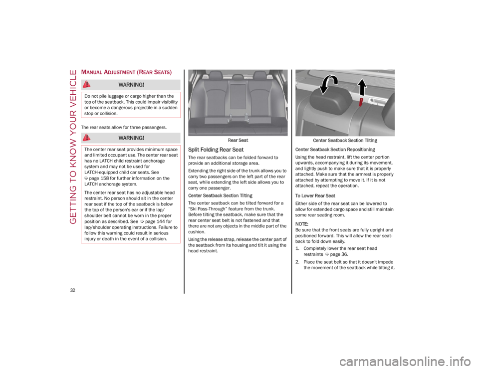
The rear seats allow for three passengers.Rear Seat
Split Folding Rear Seat
The rear seatbacks can be folded forward to
provide an additional storage area.
Extending the right side of the trunk allows you to
carry two passengers on the left part of the rear
seat, while extending the left side allows you to
carry one passenger.
Center Seatback Section Tilting
The center seatback can be tilted forward for a
“Ski Pass-Through” feature from the trunk.
Before tilting the seatback, make sure that the
rear center seat belt is not fastened and that
there are not any objects in the middle part of the
cushion.
Using the release strap, release the center part of
the seatback from its housing and tilt it using the
head restraint.Center Seatback Section Tilting
Center Seatback Section Repositioning
Using the head restraint, lift the center portion
upwards, accompanying it during its movement,
and lightly push to make sure that it is properly
attached. Make sure that the armrest is properly
attached by attempting to move it. If it is not
attached, repeat the operation.
To Lower Rear Seat
Either side of the rear seat can be lowered to
allow for extended cargo space and still maintain
some rear seating room.
NOTE:
Be sure that the front seats are fully upright and
positioned forward. This will allow the rear seat -
back to fold down easily.
1. Completely lower the rear seat head
restraints
Ú
page 36.
2. Place the seat belt so that it doesn't impede the movement of the seatback while tilting it.
WARNING!
Do not pile luggage or cargo higher than the
top of the seatback. This could impair visibility
or become a dangerous projectile in a sudden
stop or collision.
WARNING!
The center rear seat provides minimum space
and limited occupant use. The center rear seat
has no LATCH child restraint anchorage
system and may not be used for
LATCH-equipped child car seats. See
Ú
page 158 for further information on the
LATCH anchorage system.
The center rear seat has no adjustable head
restraint. No person should sit in the center
rear seat if the top of the seatback is below
the top of the person's ear or if the lap/
shoulder belt cannot be worn in the proper
position as described. See
Ú
page 144 for
lap/shoulder operating instructions. Failure to
follow this warning could result in serious
injury or death in the event of a collision.
23_GA_OM_EN_USC_t.book Page 32
Page 35 of 248
33
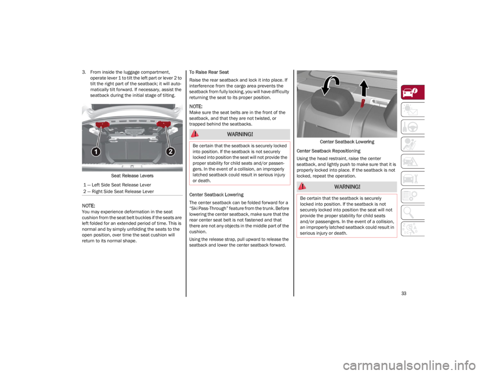
3. From inside the luggage compartment, operate lever 1 to tilt the left part or lever 2 to
tilt the right part of the seatback; it will auto -
matically tilt forward. If necessary, assist the
seatback during the initial stage of tilting.
Seat Release Levers
NOTE:
You may experience deformation in the seat
cushion from the seat belt buckles if the seats are
left folded for an extended period of time. This is
normal and by simply unfolding the seats to the
open position, over time the seat cushion will
return to its normal shape. To Raise Rear Seat
Raise the rear seatback and lock it into place. If
interference from the cargo area prevents the
seatback from fully locking, you will have difficulty
returning the seat to its proper position.
NOTE:
Make sure the seat belts are in the front of the
seatback, and that they are not twisted, or
trapped behind the seatbacks.
Center Seatback Lowering
The center seatback can be folded forward for a
“Ski Pass-Through” feature from the trunk. Before
lowering the center seatback, make sure that the
rear center seat belt is not fastened and that
there are not any objects in the middle part of the
cushion.
Using the release strap, pull upward to release the
seatback and lower the center seatback forward.
Center Seatback Lowering
Center Seatback Repositioning
Using the head restraint, raise the center
seatback, and lightly push to make sure that it is
properly locked into place. If the seatback is not
locked, repeat the operation.
1 — Left Side Seat Release Lever
2 — Right Side Seat Release Lever
WARNING!
Be certain that the seatback is securely locked
into position. If the seatback is not securely
locked into position the seat will not provide the
proper stability for child seats and/or passen -
gers. In the event of a collision, an improperly
latched seatback could result in serious injury
or death.
WARNING!
Be certain that the seatback is securely
locked into position. If the seatback is not
securely locked into position the seat will not
provide the proper stability for child seats
and/or passengers. In the event of a collision,
an improperly latched seatback could result in
serious injury or death.
23_GA_OM_EN_USC_t.book Page 33