warning lights ALFA ROMEO GIULIA 2023 Owners Manual
[x] Cancel search | Manufacturer: ALFA ROMEO, Model Year: 2023, Model line: GIULIA, Model: ALFA ROMEO GIULIA 2023Pages: 248, PDF Size: 9.62 MB
Page 11 of 248
9
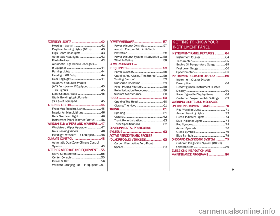
EXTERIOR LIGHTS ....................................42
Headlight Switch .................................... 42
Daytime Running Lights (DRLs) ............ 43
High Beam Headlights ........................... 43
Automatic Headlights ........................... 43
Flash-To-Pass ......................................... 43
Automatic High Beam Headlights —
If Equipped ............................................. 44 Parking Lights ........................................ 44
Headlight Off Delay ................................ 44
Rear Fog Light ........................................ 44
Adaptive Frontlight System
(AFS Function) — If Equipped ................ 45 Turn Signals ........................................... 45
Lane Change Assist ............................... 45
Static Bending Light Function
(SBL) — If Equipped ............................... 45
INTERIOR LIGHTS .....................................45
Front Map Reading Lights ..................... 45
Interior Ambient Lighting ....................... 46
Rear Overhead Light .............................. 46
Instrument Panel Dimmer Control ....... 46
WINDSHIELD WIPERS AND WASHERS....47
Windshield Wiper Operation ................. 47
Rain Sensing Wipers.............................. 48
Headlight Washers — If Equipped......... 48
CLIMATE CONTROL .................................48
Automatic Dual-Zone Climate Control
System ................................................... 49
INTERIOR STORAGE AND EQUIPMENT....55
Glove Compartment .............................. 55
Center Console ...................................... 55
Power Outlet........................................... 56
Wireless Charging Pad — If Equipped... 57
POWER WINDOWS................................... 57
Power Window Controls .........................57
Auto-Up Feature With Anti-Pinch
Protection ............................................... 58 Power Window System Initialization .....58
Wind Buffeting .......................................58
POWER SUNROOF —
IF EQUIPPED ............................................ 58
Power Sunroof ........................................ 58
Opening And Closing The Sunroof ........59
Venting Sunroof......................................59
Sunshade Operation ..............................59
Pinch Protect Feature ............................59
Re-Initialization Procedure ....................59
Sunroof Maintenance ............................60
HOOD ...................................................... 60
Opening The Hood ................................. 60
Closing The Hood ...................................61
TRUNK ...................................................... 61
Opening...................................................61
Closing ....................................................62
Trunk Re-Initialization ............................62
Trunk Specifications .............................62
ENVIRONMENTAL PROTECTION
SYSTEMS ................................................. 63
ACTIVE AERODYNAMIC SPOILER
(QUADRIFOGLIO VEHICLES) .................... 63
Carbon Fiber Active Aero Front
Spoiler .....................................................63
GETTING TO KNOW YOUR
INSTRUMENT PANEL
INSTRUMENT PANEL FEATURES ............ 64
Instrument Cluster ................................ 64
Tachometer............................................ 65
Engine Oil Temperature Gauge ............ 65
Fuel Level Gauge ................................... 66
Speedometer ......................................... 66
INSTRUMENT CLUSTER DISPLAY ........... 66
Instrument Cluster Display
Description ............................................. 66 Reconfigurable Instrument Cluster
Display .................................................... 66 Reconfigurable Display Items ............... 66
Customer Programmable Settings ....... 69
WARNING LIGHTS AND MESSAGES
ON THE INSTRUMENT PANEL ................. 70
Red Warning Lights ............................... 71
Amber Warning Lights ........................... 72
Green Indicator Lights........................... 74
Blue Indicator Lights ............................. 74
Red Symbols .......................................... 74
Amber Symbols ...................................... 76
Green Symbols ...................................... 79
Blue Symbols ......................................... 79
ONBOARD DIAGNOSTIC SYSTEM ........... 79
Onboard Diagnostic System (OBD II)
Cybersecurity ......................................... 80
EMISSIONS INSPECTION AND
MAINTENANCE PROGRAMS .................... 80
23_GA_OM_EN_USC_t.book Page 9
Page 16 of 248
SYMBOL GLOSSARY
14
SYMBOL GLOSSARY
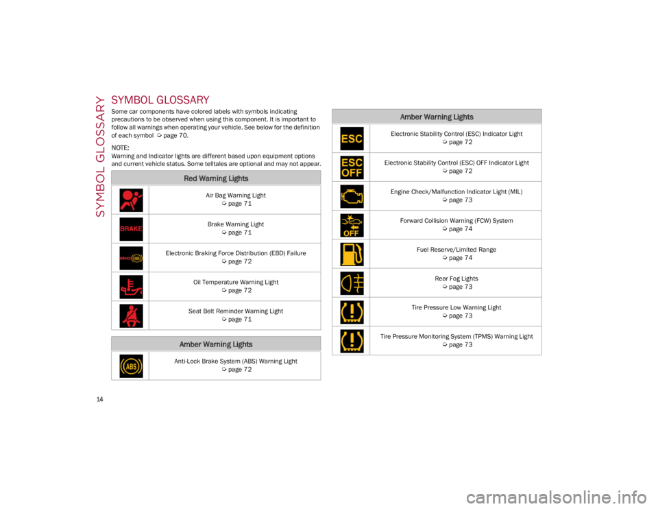
Some car components have colored labels with symbols indicating
precautions to be observed when using this component. It is important to
follow all warnings when operating your vehicle. See below for the definition
of each symbol
Ú
page 70.
NOTE:
Warning and Indicator lights are different based upon equipment options
and current vehicle status. Some telltales are optional and may not appear.
Red Warning Lights
Air Bag Warning Light
Ú
page 71
Brake Warning Light
Ú
page 71
Electronic Braking Force Distribution (EBD) Failure
Ú
page 72
Oil Temperature Warning Light
Ú
page 72
Seat Belt Reminder Warning Light
Ú
page 71
Amber Warning Lights
Anti-Lock Brake System (ABS) Warning Light
Ú
page 72
Electronic Stability Control (ESC) Indicator Light
Ú
page 72
Electronic Stability Control (ESC) OFF Indicator Light
Ú
page 72
Engine Check/Malfunction Indicator Light (MIL)
Ú
page 73
Forward Collision Warning (FCW) System
Ú
page 74
Fuel Reserve/Limited Range
Ú
page 74
Rear Fog Lights
Ú
page 73
Tire Pressure Low Warning Light
Ú
page 73
Tire Pressure Monitoring System (TPMS) Warning Light
Ú
page 73
Amber Warning Lights
23_GA_OM_EN_USC_t.book Page 14
Page 17 of 248
15
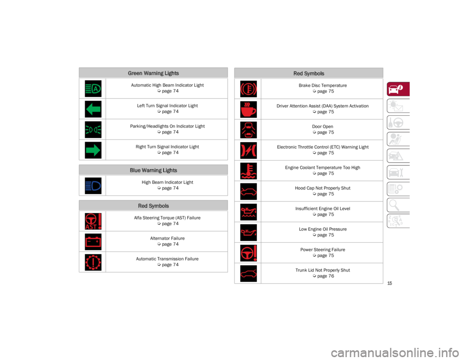
Green Warning Lights
Automatic High Beam Indicator Light
Ú
page 74
Left Turn Signal Indicator Light
Ú
page 74
Parking/Headlights On Indicator Light
Ú
page 74
Right Turn Signal Indicator Light
Ú
page 74
Blue Warning Lights
High Beam Indicator Light
Ú
page 74
Red Symbols
Alfa Steering Torque (AST) Failure
Ú
page 74
Alternator Failure
Ú
page 74
Automatic Transmission Failure
Ú
page 74
Brake Disc Temperature
Ú
page 75
Driver Attention Assist (DAA) System Activation
Ú
page 75
Door Open
Ú
page 75
Electronic Throttle Control (ETC) Warning Light
Ú
page 75
Engine Coolant Temperature Too High
Ú
page 75
Hood Cap Not Properly Shut
Ú
page 75
Insufficient Engine Oil Level
Ú
page 75
Low Engine Oil Pressure
Ú
page 75
Power Steering Failure
Ú
page 75
Trunk Lid Not Properly Shut
Ú
page 76
Red Symbols
23_GA_OM_EN_USC_t.book Page 15
Page 18 of 248
SYMBOL GLOSSARY
16
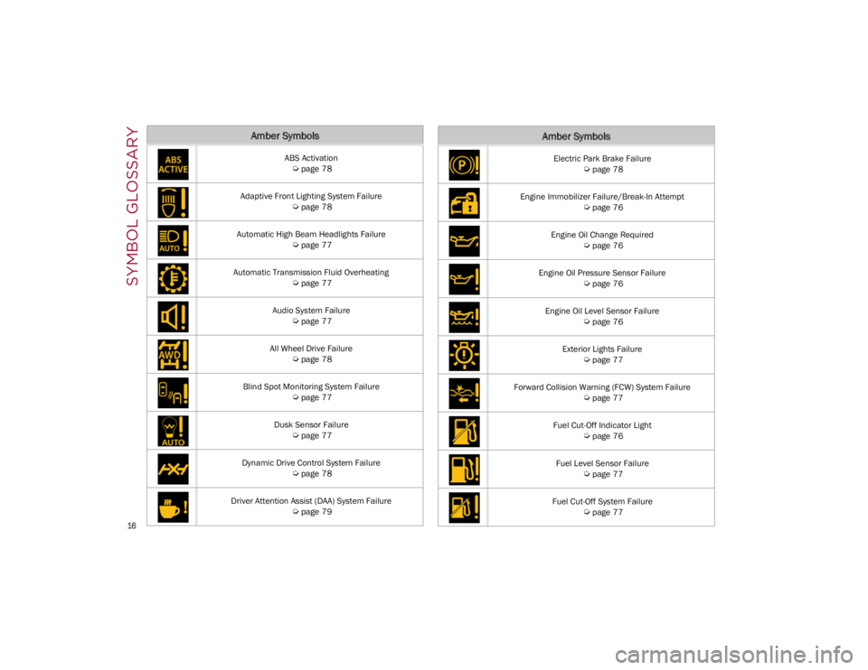
Amber Symbols
ABS Activation
Ú
page 78
Adaptive Front Lighting System Failure
Ú
page 78
Automatic High Beam Headlights Failure
Ú
page 77
Automatic Transmission Fluid Overheating
Ú
page 77
Audio System Failure
Ú
page 77
All Wheel Drive Failure
Ú
page 78
Blind Spot Monitoring System Failure
Ú
page 77
Dusk Sensor Failure
Ú
page 77
Dynamic Drive Control System Failure
Ú
page 78
Driver Attention Assist (DAA) System Failure
Ú
page 79
Electric Park Brake Failure
Ú
page 78
Engine Immobilizer Failure/Break-In Attempt
Ú
page 76
Engine Oil Change Required
Ú
page 76
Engine Oil Pressure Sensor Failure
Ú
page 76
Engine Oil Level Sensor Failure
Ú
page 76
Exterior Lights Failure
Ú
page 77
Forward Collision Warning (FCW) System Failure
Ú
page 77
Fuel Cut-Off Indicator Light
Ú
page 76
Fuel Level Sensor Failure
Ú
page 77
Fuel Cut-Off System Failure
Ú
page 77
Amber Symbols
23_GA_OM_EN_USC_t.book Page 16
Page 19 of 248
17
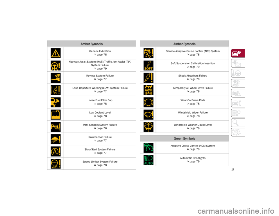
Generic Indication
Ú
page 78
Highway Assist System (HAS)/Traffic Jam Assist (TJA) System Failure
Ú
page 79
Keyless System Failure
Ú
page 77
Lane Departure Warning (LDW) System Failure
Ú
page 77
Loose Fuel Filler Cap
Ú
page 78
Low Coolant Level
Ú
page 78
Park Sensors System Failure
Ú
page 76
Rain Sensor Failure
Ú
page 77
Stop/Start System Failure
Ú
page 77
Speed Limiter System Failure
Ú
page 78
Amber Symbols
Service Adaptive Cruise Control (ACC) System
Ú
page 78
Soft Suspension Calibration Insertion
Ú
page 79
Shock Absorbers Failure
Ú
page 79
Temporary All Wheel Drive Failure
Ú
page 78
Wear On Brake Pads
Ú
page 78
Windshield Wiper Failure
Ú
page 78
Windshield Washer Liquid Level
Ú
page 79
Green Symbols
Adaptive Cruise Control (ACC) System
Ú
page 79
Automatic Headlights
Ú
page 79
Amber Symbols
23_GA_OM_EN_USC_t.book Page 17
Page 44 of 248
GETTING TO KNOW YOUR VEHICLE
42
It may be helpful to unplug the device during the
cycling process to prevent possible overheating
of the garage door or gate motor.
1. Place the ignition in the ON/RUN position.
2. Place the hand-held transmitter 1 to 3 inches (3 to 8 cm) away from the HomeLink® button
you wish to program while keeping the
HomeLink® indicator light in view.
3. Continue to push and hold the HomeLink® button while you push and release (cycle)
your hand-held transmitter every two
seconds until HomeLink® has successfully
accepted the frequency signal. The indicator
light will flash slowly and then rapidly when
fully trained.
4. Watch for the HomeLink® indicator to change flash rates. When it changes, it is
programmed. It may take up to 30 seconds or
longer in rare cases. The garage door may
open and close while you are programming.
5. Push and hold the programmed HomeLink® button and observe the indicator light.
NOTE:
•If the indicator light stays on constantly,
programming is complete and the garage door/device should activate when the HomeLink® button is pushed.
• To program the two remaining HomeLink® buttons, repeat each step for each remaining button. DO NOT erase the chan-
nels.
If you unplugged the garage door opener/device
for programming, plug it back in at this time. Reprogramming A Single HomeLink® Button
(Canadian/Gate Operator)
To reprogram a channel that has been previously
trained, follow these steps:
1. Place the ignition in the ON/RUN position.
2. Press and hold the desired HomeLink®
button until the indicator light begins to flash
after 20 seconds. Do not release the button.
3. Without releasing the button, proceed with “Canadian/Gate Operator Programming”
Step 2 and follow all remaining steps.
SECURITY
It is advised to erase all channels before you sell
or turn in your vehicle.
To do this, push and hold the two outside buttons
for 20 seconds until the indicator flashes. Note
that all channels will be erased. Individual
channels cannot be erased.
The HomeLink® universal transmitter is disabled
when the Vehicle Security system is active.
TROUBLESHOOTING TIPS
If you are having trouble programming
HomeLink®, here are some of the most common
solutions:
Replace the battery in the garage door opener
hand-held transmitter.
Push the LEARN button on the garage door
opener to complete the training for a rolling
code.
Did you unplug the device for programming
and remember to plug it back in? If you have any problems, or require assistance,
please call toll-free 1-800-355-3515 or on the
Internet at
HomeLink.com
for information or
assistance.
EXTERIOR LIGHTS
HEADLIGHT SWITCH
The headlight switch is located on the left side of
the instrument panel, next to the steering wheel.
The headlight switch controls the operation of the
headlights, parking lights, instrument panel
lights, instrument panel light dimming, interior
lights and rear fog lights.
WARNING!
Vehicle exhaust contains carbon monoxide,
a dangerous gas. Do not run your vehicle in
the garage while programming the
transmitter. Exhaust gas can cause serious
injury or death.
Your motorized door or gate will open and
close while you are programming the
universal transmitter. Do not program the
transmitter if people, pets or other objects
are in the path of the door or gate. Only use
this transmitter with a garage door opener
that has a “stop and reverse” feature as
required by Federal safety standards. This
includes most garage door opener models
manufactured after 1982. Do not use a
garage door opener without these safety
features.
23_GA_OM_EN_USC_t.book Page 42
Page 45 of 248
43
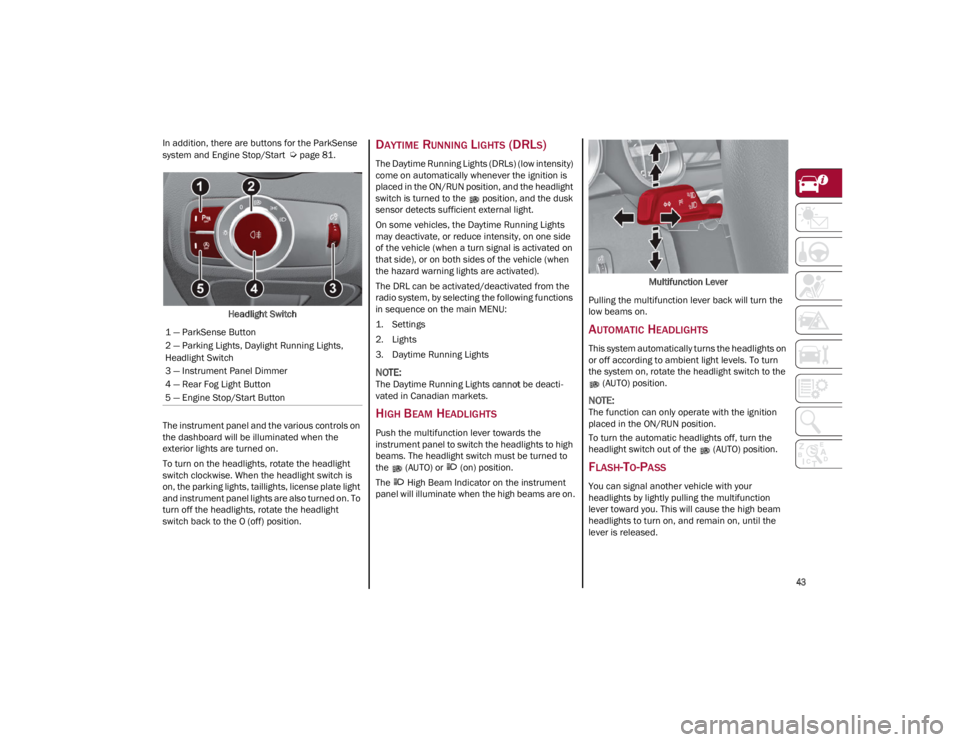
In addition, there are buttons for the ParkSense
system and Engine Stop/Start
Ú
page 81.
Headlight Switch
The instrument panel and the various controls on
the dashboard will be illuminated when the
exterior lights are turned on.
To turn on the headlights, rotate the headlight
switch clockwise. When the headlight switch is
on, the parking lights, taillights, license plate light
and instrument panel lights are also turned on. To
turn off the headlights, rotate the headlight
switch back to the O (off) position.DAYTIME RUNNING LIGHTS (DRLS)
The Daytime Running Lights (DRLs) (low intensity)
come on automatically whenever the ignition is
placed in the ON/RUN position, and the headlight
switch is turned to the position, and the dusk
sensor detects sufficient external light.
On some vehicles, the Daytime Running Lights
may deactivate, or reduce intensity, on one side
of the vehicle (when a turn signal is activated on
that side), or on both sides of the vehicle (when
the hazard warning lights are activated).
The DRL can be activated/deactivated from the
radio system, by selecting the following functions
in sequence on the main MENU:
1. Settings
2. Lights
3. Daytime Running Lights
NOTE:
The Daytime Running Lights cannot be deacti -
vated in Canadian markets.
HIGH BEAM HEADLIGHTS
Push the multifunction lever towards the
instrument panel to switch the headlights to high
beams. The headlight switch must be turned to
the (AUTO) or (on) position.
The High Beam Indicator on the instrument
panel will illuminate when the high beams are on. Multifunction Lever
Pulling the multifunction lever back will turn the
low beams on.
AUTOMATIC HEADLIGHTS
This system automatically turns the headlights on
or off according to ambient light levels. To turn
the system on, rotate the headlight switch to the (AUTO) position.
NOTE:
The function can only operate with the ignition
placed in the ON/RUN position.
To turn the automatic headlights off, turn the
headlight switch out of the (AUTO) position.
FLASH-TO-PASS
You can signal another vehicle with your
headlights by lightly pulling the multifunction
lever toward you. This will cause the high beam
headlights to turn on, and remain on, until the
lever is released.
1 — ParkSense Button
2 — Parking Lights, Daylight Running Lights,
Headlight Switch
3 — Instrument Panel Dimmer
4 — Rear Fog Light Button
5 — Engine Stop/Start Button
23_GA_OM_EN_USC_t.book Page 43
Page 46 of 248
GETTING TO KNOW YOUR VEHICLE
44
AUTOMATIC HIGH BEAM HEADLIGHTS —
I
F EQUIPPED
The Automatic High Beam Headlights system
provides increased forward lighting at night by
automating high beam control through the use of
a camera mounted on the windshield. This
camera detects vehicle specific light and
automatically switches from high beams to low
beams until the approaching vehicle is out of
view.
This function is enabled with the radio system,
and can only be activated with the light switch
turned to (AUTO).
If the high beam headlights are on, the blue icon/
indicator light will illuminate in the instrument
panel.
When the speed is higher than 25 mph (40 km/h)
and the function is active, the lights will turn off if
the multifunction lever is pushed again.
When the speed is lower than 15 mph (25 km/h)
and the function is active, the function switches
the high beam headlights off.
If the high beam headlights are operated quickly
again (pushing the multifunction lever towards
the instrument panel), the icon/indicator light
will illuminate in the instrument panel, and the
high beam headlights will turn on constantly until
the speed exceeds 25 mph (40 km/h).
When the speed of 25 mph (40 km/h) is
exceeded again, the automatic functioning is
reactivated.
If the multifunction lever is pushed again with the
Automatic High Beam Headlights activated, the
Automatic High Beam Headlights function
deactivates. To deactivate the automatic headlight function,
rotate the headlight switch to the position.
NOTE:
If the system recognizes heavy traffic areas,
the automatic functions remain disabled
independently of the vehicle’s speed.
The Automatic High Beam functionality may
also be influenced by:
• Reflections on road signs
• Dim headlights from oncoming traffic
• Poor weather conditions
• Presence of dirt or other obstructions on
the sensor
• Damage to the windshield
PARKING LIGHTS
To turn on the parking lights and instrument
panel lights, rotate the headlight switch
clockwise to the position. All of the parking
lights will turn on for eight minutes, and opening
the door activates an audible warning.
To leave only the lights on one side (right/left)
illuminated, move the multifunction lever
(located on the left side of the steering wheel) to
the side that you want to remain on. With the
parking lights on, the indicator light on the
instrument panel will illuminate.
To turn off the parking lights, rotate the headlight
switch back to the O (off) position.
HEADLIGHT OFF DELAY
To assist when exiting the vehicle, the “Headlight
Off Delay” feature will leave the headlights on for
up to 90 seconds. This delay is initiated when the
ignition is placed in the OFF position while the
headlight switch is on, and then the headlight
switch is cycled off. Headlight delay can be
canceled by either turning on the headlights or
side lights, or by placing the ignition in the ON
position.
The function can be activated from the radio
system by selecting the following functions in
sequence on the main menu:
1. Settings
2. Lights
3. Headlight Off Delay
REAR FOG LIGHT
The rear fog lights may be operated as desired
when visibility is poor due to fog. The rear fog light
button is integrated with the headlight switch.
Push the button to turn the rear fog lights on/
off.
The lights can be turned off by pushing the
button again or by turning the headlight switch to
the O (off) position and holding it there for a few
seconds.
NOTE:
The headlight switch must first be turned to the
parking lights or headlights position before the
rear fog light button can be pushed.
When the engine is stopped with the rear fog
lights on, they will remain off the next time the
engine is started.
23_GA_OM_EN_USC_t.book Page 44
Page 58 of 248
GETTING TO KNOW YOUR VEHICLE
56
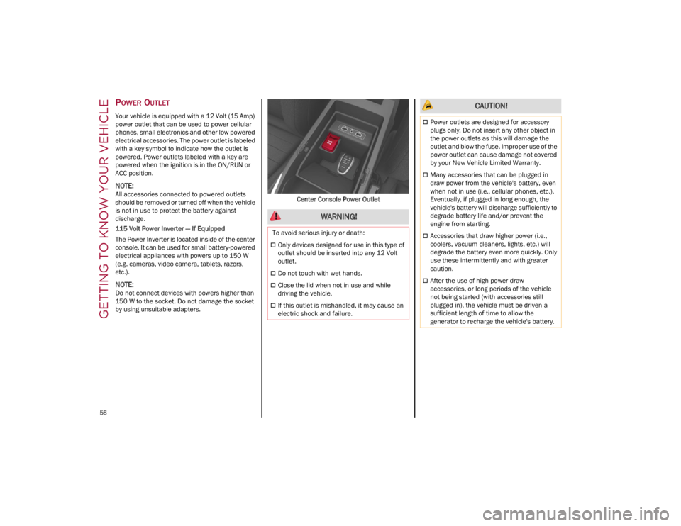
POWER OUTLET
Your vehicle is equipped with a 12 Volt (15 Amp)
power outlet that can be used to power cellular
phones, small electronics and other low powered
electrical accessories. The power outlet is labeled
with a key symbol to indicate how the outlet is
powered. Power outlets labeled with a key are
powered when the ignition is in the ON/RUN or
ACC position.
NOTE:
All accessories connected to powered outlets
should be removed or turned off when the vehicle
is not in use to protect the battery against
discharge.
115 Volt Power Inverter — If Equipped
The Power Inverter is located inside of the center
console. It can be used for small battery-powered
electrical appliances with powers up to 150 W
(e.g. cameras, video camera, tablets, razors,
etc.).
NOTE:
Do not connect devices with powers higher than
150 W to the socket. Do not damage the socket
by using unsuitable adapters.Center Console Power Outlet
WARNING!
To avoid serious injury or death:
Only devices designed for use in this type of
outlet should be inserted into any 12 Volt
outlet.
Do not touch with wet hands.
Close the lid when not in use and while
driving the vehicle.
If this outlet is mishandled, it may cause an
electric shock and failure.
CAUTION!
Power outlets are designed for accessory
plugs only. Do not insert any other object in
the power outlets as this will damage the
outlet and blow the fuse. Improper use of the
power outlet can cause damage not covered
by your New Vehicle Limited Warranty.
Many accessories that can be plugged in
draw power from the vehicle's battery, even
when not in use (i.e., cellular phones, etc.).
Eventually, if plugged in long enough, the
vehicle's battery will discharge sufficiently to
degrade battery life and/or prevent the
engine from starting.
Accessories that draw higher power (i.e.,
coolers, vacuum cleaners, lights, etc.) will
degrade the battery even more quickly. Only
use these intermittently and with greater
caution.
After the use of high power draw
accessories, or long periods of the vehicle
not being started (with accessories still
plugged in), the vehicle must be driven a
sufficient length of time to allow the
generator to recharge the vehicle's battery.
23_GA_OM_EN_USC_t.book Page 56
Page 63 of 248
61
CLOSING THE HOOD
To close, lower the hood to approximately
16 inches (40 cm) from the engine compartment
then let it drop. Make sure that the hood is
completely closed and fully latched.
NOTE:
Since the hood is equipped with a double locking
system, one for each side, check that it is closed
on both its sides.
TRUNK
The trunk unlocking is electrically operated and is
deactivated when the vehicle is in motion.
OPENING
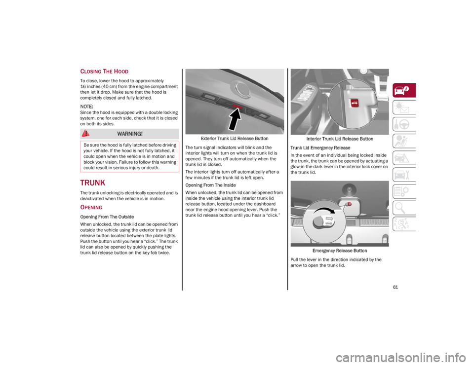
Opening From The Outside
When unlocked, the trunk lid can be opened from
outside the vehicle using the exterior trunk lid
release button located between the plate lights.
Push the button until you hear a “click.” The trunk
lid can also be opened by quickly pushing the
trunk lid release button on the key fob twice.Exterior Trunk Lid Release Button
The turn signal indicators will blink and the
interior lights will turn on when the trunk lid is
opened. They turn off automatically when the
trunk lid is closed.
The interior lights turn off automatically after a
few minutes if the trunk lid is left open.
Opening From The Inside
When unlocked, the trunk lid can be opened from
inside the vehicle using the interior trunk lid
release button, located under the dashboard
near the engine hood opening lever. Push the
trunk lid release button until you hear a “click.” Interior Trunk Lid Release Button
Trunk Lid Emergency Release
In the event of an individual being locked inside
the trunk, the trunk can be opened by actuating a
glow-in-the-dark lever in the interior lock cover on
the trunk lid.
Emergency Release Button
Pull the lever in the direction indicated by the
arrow to open the trunk lid.
WARNING!
Be sure the hood is fully latched before driving
your vehicle. If the hood is not fully latched, it
could open when the vehicle is in motion and
block your vision. Failure to follow this warning
could result in serious injury or death.
23_GA_OM_EN_USC_t.book Page 61