warning Alfa Romeo Giulietta 2017 Repair Manual
[x] Cancel search | Manufacturer: ALFA ROMEO, Model Year: 2017, Model line: Giulietta, Model: Alfa Romeo Giulietta 2017Pages: 212, PDF Size: 4.56 MB
Page 97 of 212
A punctured tyre or a burnt-out bulb?
At times, a problem may interfere with our journey.
The pages on emergencies can help you to deal with critical
situations independently and with calm. In an emergency we
recommend that you call the freephone number found in the
Warranty Booklet. You can also use the universal, national or
international freephone number to find your nearest Authorised
Alfa Romeo Dealership.
IN AN EMERGENCY
HAZARD WARNING LIGHTS........................96
REPLACING A BULB.............................96
REPLACING AN EXTERIOR BULB....................100
REPLACING FUSES............................102
CHANGING A WHEEL ...........................110
FIX&GO KIT.................................113
JUMP STARTING..............................116
FUEL CUT-OFF SYSTEM . ........................117
TCT TRANSMISSION - KEY REMOVAL.................117
TOWING THE CAR.............................119
Page 98 of 212
HAZARD WARNING LIGHTS
Operation
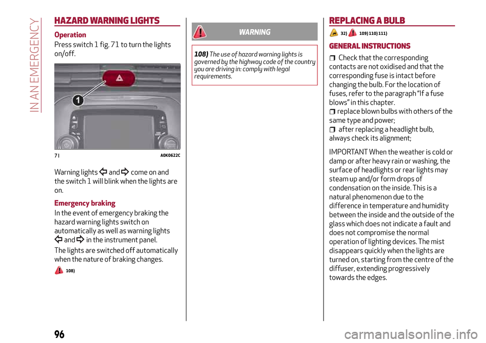
Press switch 1 fig. 71 to turn the lights
on/off.
Warning lights
andcome on and
the switch 1 will blink when the lights are
on.
Emergency braking
In the event of emergency braking the
hazard warning lights switch on
automatically as well as warning lights
andin the instrument panel.
The lights are switched off automatically
when the nature of braking changes.
108)
WARNING
108)The use of hazard warning lights is
governed by the highway code of the country
you are driving in: comply with legal
requirements.
REPLACING A BULB
32)109) 110) 111)
GENERAL INSTRUCTIONS
Check that the corresponding
contacts are not oxidised and that the
corresponding fuse is intact before
changing the bulb. For the location of
fuses, refer to the paragraph “If a fuse
blows” in this chapter.
replace blown bulbs with others of the
same type and power;
after replacing a headlight bulb,
always check its alignment;
IMPORTANT When the weather is cold or
damp or after heavy rain or washing, the
surface of headlights or rear lights may
steam up and/or form drops of
condensation on the inside. This is a
natural phenomenon due to the
difference in temperature and humidity
between the inside and the outside of the
glass which does not indicate a fault and
does not compromise the normal
operation of lighting devices. The mist
disappears quickly when the lights are
turned on, starting from the centre of the
diffuser, extending progressively
towards the edges.71A0K0622C
96
IN AN EMERGENCY
Page 101 of 212
WARNING
109)Modifications or repairs to the electric system that are not carried out properly or do not take the system technical specifications into
account can cause malfunctions leading to the risk of fire.
110)Halogen bulbs contain pressurised gas, in the case of breakage they may burst causing glass fragments to be projected outwards.
111)Due to the high power supply voltage, gas discharge bulbs (Bi-Xenon) should only be replaced by specialised personnel: danger of death!
Contact an Alfa Romeo Dealership.
99
Page 111 of 212
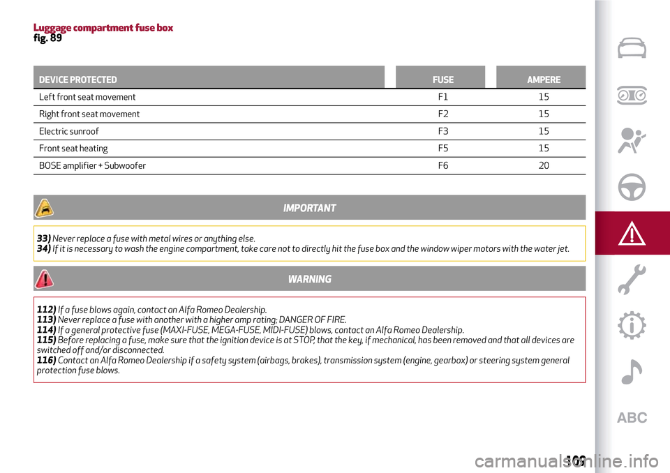
Luggage compartment fuse boxfig. 89
DEVICE PROTECTEDFUSE AMPERE
Left front seat movementF1
15
Right front seat movementF2 15
Electric sunroofF3 15
Front seat heatingF5 15
BOSE amplifier + SubwooferF6 20
IMPORTANT
33)Never replace a fuse with metal wires or anything else.
34)If it is necessary to wash the engine compartment, take care not to directly hit the fuse box and the window wiper motors with the water jet.
WARNING
112)If a fuse blows again, contact an Alfa Romeo Dealership.
113)Never replace a fuse with another with a higher amp rating; DANGER OF FIRE.
114)If a general protective fuse (MAXI-FUSE, MEGA-FUSE, MIDI-FUSE) blows, contact an Alfa Romeo Dealership.
115)Before replacing a fuse, make sure that the ignition device is at STOP, that the key, if mechanical, has been removed and that all devices are
switched off and/or disconnected.
116)Contact an Alfa Romeo Dealership if a safety system (airbags, brakes), transmission system (engine, gearbox) or steering system general
protection fuse blows.
109
Page 114 of 212
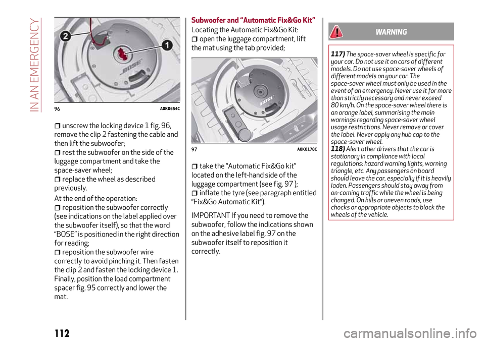
unscrew the locking device 1 fig. 96,
remove the clip 2 fastening the cable and
then lift the subwoofer;
rest the subwoofer on the side of the
luggage compartment and take the
space-saver wheel;
replace the wheel as described
previously.
At the end of the operation:
reposition the subwoofer correctly
(see indications on the label applied over
the subwoofer itself), so that the word
“BOSE” is positioned in the right direction
for reading;
reposition the subwoofer wire
correctly to avoid pinching it. Then fasten
the clip 2 and fasten the locking device 1.
Finally, position the load compartment
spacer fig. 95 correctly and lower the
mat.Subwoofer and “Automatic Fix&Go Kit”
Locating the Automatic Fix&Go Kit:
open the luggage compartment, lift
the mat using the tab provided;
take the “Automatic Fix&Go kit”
located on the left-hand side of the
luggage compartment (see fig. 97 );
inflate the tyre (see paragraph entitled
“Fix&Go Automatic Kit”).
IMPORTANT If you need to remove the
subwoofer, follow the indications shown
on the adhesive label fig. 97 on the
subwoofer itself to reposition it
correctly.
WARNING
117)The space-saver wheel is specific for
your car. Do not use it on cars of different
models. Do not use space-saver wheels of
different models on your car. The
space-saver wheel must only be used in the
event of an emergency. Never use it for more
than strictly necessary and never exceed
80 km/h. On the space-saver wheel there is
an orange label, summarising the main
warnings regarding space-saver wheel
usage restrictions. Never remove or cover
the label. Never apply any hub cap to the
space-saver wheel.
118)Alert other drivers that the car is
stationary in compliance with local
regulations: hazard warning lights, warning
triangle, etc. Any passengers on board
should leave the car, especially if it is heavily
laden. Passengers should stay away from
on-coming traffic while the wheel is being
changed. On hills or uneven roads, use
chocks or appropriate objects to block the
wheels of the vehicle.
96A0K0654C
97A0K0178C
112
IN AN EMERGENCY
Page 116 of 212
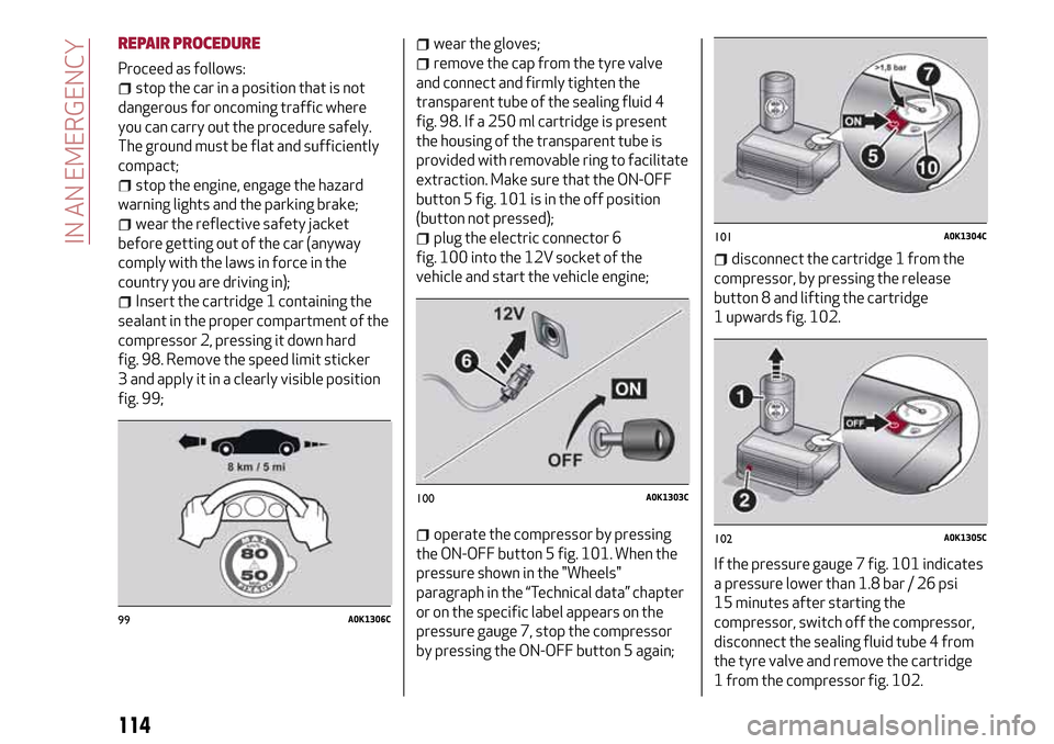
REPAIR PROCEDURE
Proceed as follows:
stop the car in a position that is not
dangerous for oncoming traffic where
you can carry out the procedure safely.
The ground must be flat and sufficiently
compact;
stop the engine, engage the hazard
warning lights and the parking brake;
wear the reflective safety jacket
before getting out of the car (anyway
comply with the laws in force in the
country you are driving in);
Insert the cartridge 1 containing the
sealant in the proper compartment of the
compressor 2, pressing it down hard
fig. 98. Remove the speed limit sticker
3 and apply it in a clearly visible position
fig. 99;
wear the gloves;
remove the cap from the tyre valve
and connect and firmly tighten the
transparent tube of the sealing fluid 4
fig. 98. If a 250 ml cartridge is present
the housing of the transparent tube is
provided with removable ring to facilitate
extraction. Make sure that the ON-OFF
button 5 fig. 101 is in the off position
(button not pressed);
plug the electric connector 6
fig. 100 into the 12V socket of the
vehicle and start the vehicle engine;
operate the compressor by pressing
the ON-OFF button 5 fig. 101. When the
pressure shown in the "Wheels"
paragraph in the “Technical data” chapter
or on the specific label appears on the
pressure gauge 7, stop the compressor
by pressing the ON-OFF button 5 again;
disconnect the cartridge 1 from the
compressor, by pressing the release
button 8 and lifting the cartridge
1 upwards fig. 102.
If the pressure gauge 7 fig. 101 indicates
a pressure lower than 1.8 bar / 26 psi
15 minutes after starting the
compressor, switch off the compressor,
disconnect the sealing fluid tube 4 from
the tyre valve and remove the cartridge
1 from the compressor fig. 102.
99A0K1306C
100A0K1303C
101A0K1304C
102A0K1305C
114
IN AN EMERGENCY
Page 117 of 212
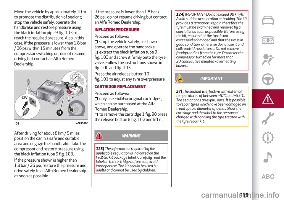
Move the vehicle by approximately 10 m
to promote the distribution of sealant;
stop the vehicle safely, operate the
handbrake and restore pressure using
the black inflation pipe 9 fig. 103 to
reach the required pressure. Also in this
case, if the pressure is lower than 1.8 bar
/ 26 psi within 15 minutes from the
compressor switching on, do not resume
driving but contact an Alfa Romeo
Dealership.
After driving for about 8 km / 5 miles,
position the car in a safe and suitable
area and engage the handbrake. Take the
compressor and restore pressure using
the black inflation tube 9 fig. 103.
If the pressure shown is higher than
1.8 bar / 26 psi, restore the pressure and
drive safely to an Alfa Romeo Dealership
as soon as possible.If the pressure is lower than 1.8 bar /
26 psi, do not resume driving but contact
an Alfa Romeo Dealership.
INFLATION PROCEDURE
Proceed as follows:
stop the vehicle safely, as shown
above, and operate the handbrake;
extract the black inflation tube 9
fig. 103 and screw it firmly onto the tyre
valve. Follow the instructions shown in
fig. 100 and fig. 103.
Press the air release button 10
fig. 101 to adjust any tyre overpressure.
CARTRIDGE REPLACEMENT
Proceed as follows:
only use Fix&Go original cartridges,
which can be purchased at the Alfa
Romeo Dealership.
to remove the cartridge 1 fig. 98 press
the release button 8 fig. 102 and lift it.
WARNING
123)The information required by the
applicable regulation is indicated on the
Fix&Go kit package label. Carefully read the
label on the cartridge before use, avoid
improper use. The kit should be used by
adults and cannot be used by children.124)IMPORTANT: Do not exceed 80 km/h.
Avoid sudden acceleration or braking. The kit
provides a temporary repair, therefore the
tyre must be examined and repaired by a
specialist as soon as possible. Before using
the kit, ensure that the tyre is not
excessively damaged and that the rim is in
good condition, otherwise do not use it and
call roadside assistance. Do not remove
foreign bodies from the tyre. Do not let the
compressor turned on for more than
20 consecutive minutes - overheating
hazard.
IMPORTANT
37)The sealant is effective with external
temperatures of between -40°C and +55°C.
The sealant has an expiry date. It is possible
to repair tyres which have been damaged on
tread up to a diameter of 6 mm. Show the
cartridge and the label to the personnel
charged with handling the tyre treated with
the tyre repair kit.
103A0K1307C
115
Page 118 of 212
JUMP STARTING
STARTING THE ENGINE
If the iconstays on constantly on the
instrument panel, contact the Alfa
Romeo Dealership immediately.
JUMP STARTING
If the battery is flat, start the engine
using an auxiliary battery with the same
capacity or a little higher than the flat
one.
38) 39)125)
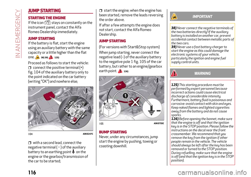
Proceed as follows to start the vehicle:
connect the positive terminal (+)
fig. 104 of the auxiliary battery only to
the point indicated on the car battery
(writing "OK") and nowhere else;
with a second lead, connect the
negative terminal(−)oftheauxiliary
battery to an earthing point
on the
engine or the gearbox/transmission of
the car to be started;
start the engine; when the engine has
been started, remove the leads reversing
the order above.
If after a few attempts the engine does
not start, contact the Alfa Romeo
Dealership.
JUMP STARTING
(For versions with Start&Stop system)
When jump starting, never connect the
negative lead (–) of the auxiliary battery
to the negative pole 1 fig. 105 of the car
battery, but rather to an engine/gearbox
earth point.
126)
BUMP STARTING
Never, under any circumstances, jump
start the engine by pushing, towing or
coasting downhill.
IMPORTANT
38)Never connect the negative terminals of
the two batteries directly! If the auxiliary
battery is installed on another car, prevent
accidental contact between metallic parts of
the two cars.
39)Never use a fast battery-charger to
start the engine as this could damage the
electronic systems of your vehicle,
particularly the ignition and engine fuel
supply control units.
WARNING
125)This starting procedure must be
performed by expert personnel because
incorrect actions could cause electrical
discharge of considerable intensity.
Furthermore, battery fluid is poisonous and
corrosive: avoid contact with skin and eyes.
Keep naked flames and lighted cigarettes
away from the battery and do not cause
sparks.
126)Before opening the bonnet, make sure
that the engine is off and that the ignition
key is in the STOP position. Please follow the
instructions on the decal near the front
crossmember. We recommend that you
remove the key from the ignition if other
people remain in the vehicle. The vehicle
should always be left after the key has been
removed or turned to the STOP position.
During refuelling, make sure that the engine
is off (and that the ignition key is in the STOP
position).
104A0K0247C
105A0K0755C
116
IN AN EMERGENCY
Page 119 of 212
FUEL CUT-OFFSYSTEM
Operation
This intervenes in the case of an impact
causing:
the fuel supply cut-off with the engine
consequently switching off;
the automatic unlocking of the doors;
the switching on of the interior lights.
The intervention of the system is
indicated by a message shown on the
display.
Carefully check the vehicle for fuel leaks,
for instance in the engine compartment,
under the vehicle or near the tank area.
127)
After a collision, turn the ignition key to
STOP to prevent the battery from
running down.
To restore the correct operation of the
car, proceed as follows:
turn the ignition key to the MAR
position;
activate the right direction indicator;
deactivate the right direction
indicator;
activate the left direction indicator;
deactivate the left direction indicator;
activate the right direction indicator;
deactivate the right direction
indicator;
activate the left direction indicator;
deactivate the left direction indicator;
ignition key turned to the OFF
position;
turn the ignition key to the MAR-ON
position.
WARNING
127)If, after an impact, you smell fuel or
notice leaks from the fuel system, do not
reactivate the system to avoid the risk of
fire.
TCT TRANSMISSION - KEY
REMOVAL
The ignition key can be removed only if
the gear lever is in position P (Park).
If the battery is flat and the ignition key is
engaged, the latter is locked in position.
To remove the key manually, proceed as
follows:
apply the handbrake;
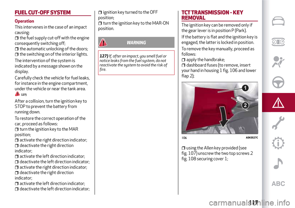
dashboard fuses (to remove, insert
your hand in housing 1 fig. 106 and lower
flap 2);
using the Allen key provided (see
fig. 107) unscrew the two top screws 2
fig. 108 securing cover 1;
106A0K0527C
117
Page 122 of 212
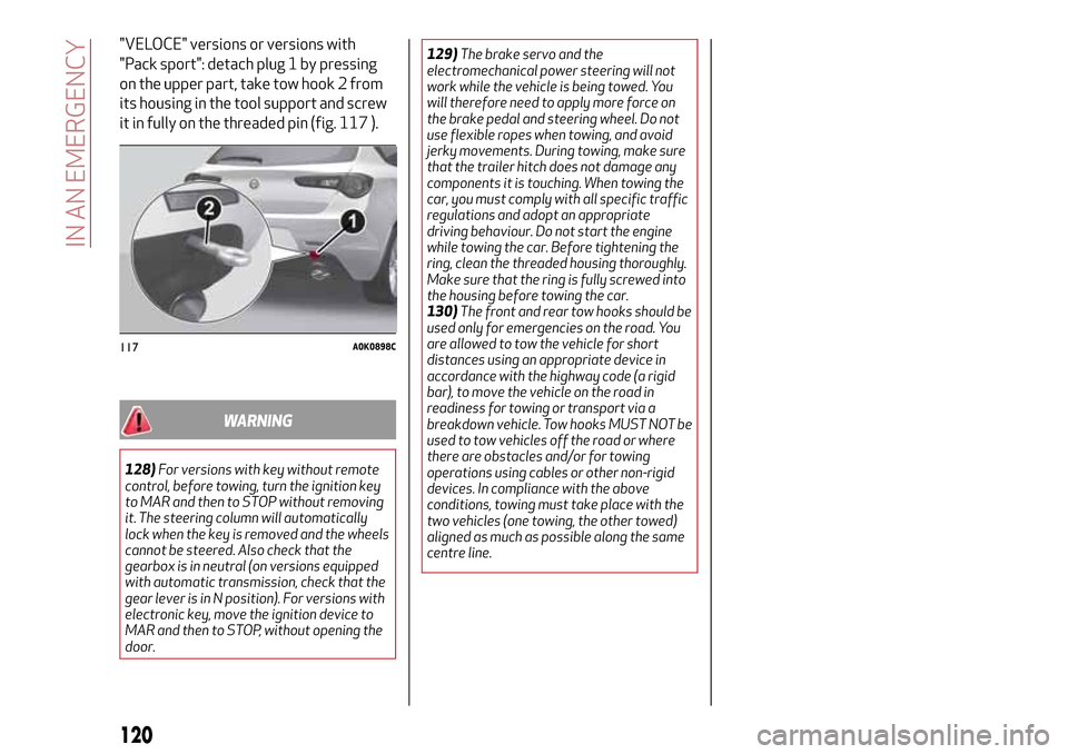
"VELOCE" versions or versions with
"Pack sport": detach plug 1 by pressing
on the upper part, take tow hook 2 from
its housing in the tool support and screw
it in fully on the threaded pin (fig. 117 ).
WARNING
128)For versions with key without remote
control, before towing, turn the ignition key
to MAR and then to STOP without removing
it. The steering column will automatically
lock when the key is removed and the wheels
cannot be steered. Also check that the
gearbox is in neutral (on versions equipped
with automatic transmission, check that the
gear lever is in N position). For versions with
electronic key, move the ignition device to
MAR and then to STOP, without opening the
door.129)The brake servo and the
electromechanical power steering will not
work while the vehicle is being towed. You
will therefore need to apply more force on
the brake pedal and steering wheel. Do not
use flexible ropes when towing, and avoid
jerky movements. During towing, make sure
that the trailer hitch does not damage any
components it is touching. When towing the
car, you must comply with all specific traffic
regulations and adopt an appropriate
driving behaviour. Do not start the engine
while towing the car. Before tightening the
ring, clean the threaded housing thoroughly.
Make sure that the ring is fully screwed into
the housing before towing the car.
130)The front and rear tow hooks should be
used only for emergencies on the road. You
are allowed to tow the vehicle for short
distances using an appropriate device in
accordance with the highway code (a rigid
bar), to move the vehicle on the road in
readiness for towing or transport via a
breakdown vehicle. Tow hooks MUST NOT be
used to tow vehicles off the road or where
there are obstacles and/or for towing
operations using cables or other non-rigid
devices. In compliance with the above
conditions, towing must take place with the
two vehicles (one towing, the other towed)
aligned as much as possible along the same
centre line.
117A0K0898C
120
IN AN EMERGENCY