dashboard Alfa Romeo GT 2005 Owner handbook (in English)
[x] Cancel search | Manufacturer: ALFA ROMEO, Model Year: 2005, Model line: GT, Model: Alfa Romeo GT 2005Pages: 307, PDF Size: 6.05 MB
Page 13 of 307
GETTING TO KNOW YOUR CAR
11
ELECTRONIC ALARM
DESCRIPTION
The system comprises: a transmitter,
receiver, control unit with siren and volu-
metric sensors. The electronic alarm is
controlled by the receiver incorporated in
the instrument cluster and it is turned on
and off by the remote control in the key
which sends the crypted and variable
code. The electronic alarm controls: the
unlawful opening of doors, bonnet and
boot (perimetral protection), operation of
the ignition key, battery cable cutting, the
presence of moving bodies in the passen-
ger compartment (volumetric protection),
any abnormal raising/sloping of the car
(for versions/markets where applicable)
and central door locking. It also makes it
possible to cut off the volumetric protec-
tion.
IMPORTANTThe engine inhibitor
function is guaranteed by the Alfa Romeo
CODE system which is activated automati-
cally when the ignition key is removed.The remote control is incorporated in the
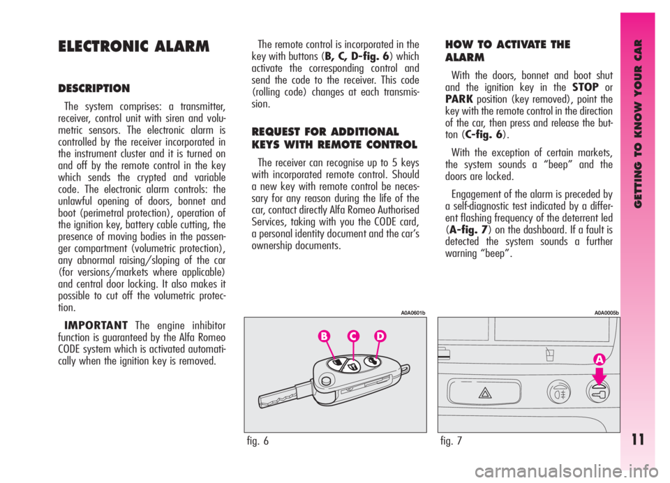
key with buttons (B, C, D-fig. 6) which
activate the corresponding control and
send the code to the receiver. This code
(rolling code) changes at each transmis-
sion.
REQUEST FOR ADDITIONAL
KEYS WITH REMOTE CONTROL
The receiver can recognise up to 5 keys
with incorporated remote control. Should
a new key with remote control be neces-
sary for any reason during the life of the
car, contact directly Alfa Romeo Authorised
Services, taking with you the CODE card,
a personal identity document and the car’s
ownership documents.
HOW TO ACTIVATE THE
ALARM
With the doors, bonnet and boot shut
and the ignition key in the STOPor
PARKposition (key removed), point the
key with the remote control in the direction
of the car, then press and release the but-
ton (C-fig. 6).
With the exception of certain markets,
the system sounds a “beep” and the
doors are locked.
Engagement of the alarm is preceded by
a self-diagnostic test indicated by a differ-
ent flashing frequency of the deterrent led
(A-fig. 7) on the dashboard. If a fault is
detected the system sounds a further
warning “beep”.
fig. 6
A0A0601b
fig. 7
A0A0005b
Page 14 of 307
GETTING TO KNOW YOUR CAR
12
– if the led continues flashing, but at dif-
ferent intervals than normal, this means
that different attempts to break in have
occurred. Through the number of flashes it
is possible to identify the type of attempt:
1 flash:one or more doors
2 flashes:tailgate
3 flashes:bonnet
4 flashes:ultrasounds
5 flashes:abnormal vehicle lift-
ing/sloping (for ver-
sions/markets where
applicable)
6 flashes:tampering with car start-
ing cables
7 flashes:tampering with battery
cables or cutting emer-
gency key cables
8 flashes:connection line to sen-
sors and siren
9 flashes:at least three causes of
alarm. Surveillance
After switching on, the flashing of the
deterrent led (A-fig. 7) on the dash-
board indicates the system surveillance
mode. The led flashes throughout this
period.
IMPORTANTOperation of the elec-
tronic alarm is adapted at the origin to the
rules of the different countries.
Self-diagnostic functions
and door, bonnet, boot control
If, after engaging the alarm, a second
“beep” is sounded, switch off the system
pressing the button (B-fig. 6), check
that the doors, bonnet and tailgate are
properly shut, then switch the system on
again pressing the button (C). Otherwise,
the door, bonnet or tailgate that is not
shut properly will be excluded from the
alarm system control.
If the doors, bonnet and boot are shut
correctly and the control signal is repeat-
ed, the system self-diagnostic has detect-
ed a system operating fault. It is therefore
necessary to contact Alfa Romeo
Authorised Services.HOW TO DEACTIVATE
THE ALARM
To deactivate the alarm press the button
(B-fig. 6) of the key with remote control.
The system will react as follows (with the
exception of certain markets):
– two brief flashes of the direction indi-
cators
– two brief “beeps” of the system
– door unlocking.
IMPORTANTIf when the system is
turned off the deterrent led (A-fig. 7)
on the dashboard stays on (maximum 2
minutes or until the ignition key is set to
MAR) the following should be borne in
mind:
Page 15 of 307

GETTING TO KNOW YOUR CAR
13
WHEN THE ALARM
IS TRIGGERED
When the system is on, the alarm comes
into action in the following cases:
– opening of one of the doors, bonnet or
tailgate;
– disconnection of the battery or sec-
tioning of electric cables;
– intrusion in the passenger compart-
ment, for example breakage of windows
(volumetric protection);
– attempt to start the engine (key in
MARposition);
– abnormal car lifting/sloping (for ver-
sions/markets where applicable).
Depending on the markets, the cutting in
of the alarm causes operation of the siren
and hazard warning ligths (for about 26
seconds). The ways of operating and the
number of cycles may vary depending on
the markets.
A maximum number of cycles is howev-
er envisaged.
Once the alarm cycle has ended, the sys-
tem resumes its normal control function.
VOLUMETRIC PROTECTION
To make sure that the protection system
works correctly the side windows and sun-
roof (if fitted) must be properly shut.
The function can be cut off (if, for exam-
ple, leaving animals in the car) carrying
out the following operations in rapid suc-
cession: starting from the condition with
the ignition key at MAR, move the key
toSTOP, then immediately back to
MARand then to STOPagain, then
remove the ignition key.
The deterrent led (A-fig. 7) on the
dashboard lights up for about 2 seconds to
confirm that the function has been cut off.
To restore volumetric protection, move
the and keep the ignition key at MARfor
over 30 seconds.
If, with the volumetric protection func-
tion deactivated, an electric control con-
trolled by the ignition key at MAR(e.g.
power windows) turn the ignition key to
MAR, operate the control and move the
key to STOPin a maximum time of 30
seconds. This way volumetric protection is
not restored.
HOW TO CUT OFF
THE ALARM SYSTEM
To deactivate the alarm system com-
pletely (for instance during prolonged
inactivity of the vehicle) simply lock the
car turning the key in the lock.
MINISTERIAL CERTIFICATION
In accordance with the law in force in
each country, on the subject of radio fre-
quency, we wish to point out that for the
markets in which the transmitter needs to
be marked, the certification number is
given on the component.
Depending on the versions/markets, the
code may also be given on the transmitter
and/or on the receiver.
Page 17 of 307
It is absolutely forbidden
to carry out whatever af-
ter-market operation in-
volving steering system or steer-
ing column modifications (e.g.: in-
stallation of anti-theft Device) that
could badly affect performance and
safety, cause the lapse of warran-
ty and also result in non-compli-
ance of the car with homologation
requirements.
GETTING TO KNOW YOUR CAR
15
STEERING LOCK
Engaging:
– move the key to STOPorPARK,
then remove the key and turn the steering
wheel slightly to facilitate the locking
action.
Disengaging:
– turn the key to MARgently rocking
the steering wheel from side to side.
Never remove the ignition
key with the car on the
move. The steering wheel
would lock automatically the first
time the steering wheel is turned.
This also occurs if the car is towed.
DOORS
Before opening a door, al-
ways make sure that it can
be done safely.
OPENING/CLOSING
FROM OUTSIDE
Front doors
– To open the driver's door turn the key
clockwise and to open the passengers' door,
optional for versions/markets where applic-
able, turn the key anti-clockwise, then re-
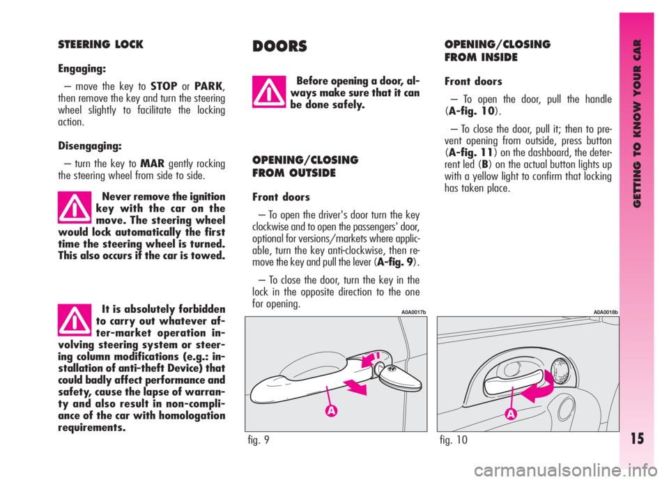
move the key and pull the lever (A-fig. 9).
– To close the door, turn the key in the
lock in the opposite direction to the one
for opening.
fig. 9
A0A0017b
fig. 10
A0A0018b
OPENING/CLOSING
FROM INSIDE
Front doors
– To open the door, pull the handle
(A-fig. 10).
– To close the door, pull it; then to pre-
vent opening from outside, press button
(A-fig. 11) on the dashboard, the deter-
rent led (B) on the actual button lights up
with a yellow light to confirm that locking
has taken place.
Page 34 of 307
GETTING TO KNOW YOUR CAR
32
CARRYING CHILDREN
SAFELY
For the best level of protection in the
event of a crash, all occupants must trav-
el seated and secured by suitable restraint
systems. This is even more important for
children.
According to 2003/20/EC Directive,
this prescription is compulsory for all
European Community countries.
Compared with adults, a child’s head is
proportionately larger and heavier than
the rest of the body, while muscles and
bone structure are not completely devel-
oped. Therefore, in order to restrain them
correctly in the event of a crash, different
systems are needed than adult seat belts.
The results of research on the best pro-
tection for a child are summarised in
European Standard ECE- R44, which in
addition to making them compulsory, sub-
divides restraint systems into five groups:
Group 0 - until 10 kg in weight
Group 0+ - until 13 kg in weight
Group 1 9 - 18 kg in weight
Group 2 15 - 25 kg in weight
Group 3 22 - 36 kg in weightAs it may be noted, the groups overlap
partly and in fact, in commerce it is possible
to find devices that cover more than one
weight group.
All the restraint devices must bear the
homologation data, together with the con-
trol brand, on a solidly fixed label which
must absolutely not be removed.
Over 1,50 m in height, from the point of
view of restraint systems, children are con-
sidered as adults and wear belt normally.
The Lineaccessori Alfa Romeo includes
seats for each weight group, which are the
recommended choice because they have
been designed and specifically experi-
mented for Alfa Romeo cars.
With passenger’s air bag
active, never place child’s
seats with the cradle fac-
ing backwards since the air bag ac-
tivation could cause to the child se-
rious injuries, even mortal, re-
gardless of the seriousness of the
crash that triggered it. You are ad-
vised to carry children always with
proper restraint systems on the
rear seats, as this is the most pro-
tected position in the case of a
crash.SERIOUS DANGER
If it is absolutely
necessary to carry a
child on the front passenger seat
with the cradle child’s seat facing
backwards, the front passenger’s
air bag must be deactivated using
the key switch. In this case it is ab-
solutely necessary to check the
warning light Fon the instru-
ment panel (see paragraph “Pas-
senger’s front air bag”) to make
sure that deactivation has actual-
ly taken place. Moreover, the front
passenger’s seat shall be adjust-
ed in the most backward position
to prevent any contact between
the child’s seat and the dashboard.
Page 40 of 307

GETTING TO KNOW YOUR CAR
38
Group 1
For proper mounting proceed as follows:
– check whether the release lever (B-
fig. 49) is at rest position (inward);
– find the presetting brackets (A), then
position the child restraint system with fas-
tening devices (C) aligned with the brack-
ets;
– push the child restraint system until
hearing the locking clicks;
– check proper locking by moving the
child’s seat with force: the built-in safety
mechanism actually inhibits improper cou-
pling with only one coupling locked.FRONT AND SIDE
AIR BAGS
The car is fitted with front air bags for
the driver and for the passenger (side
bags - window bags).
FRONT AIR BAGS
The front air bag (driver’s and passen-
ger’s) has been designed to protect the
occupants in the event of of head-on
crashes of medium-high severity by plac-
ing the cushion between the occupant and
the steering wheel or dashboard.
Front air bags are designed to protect
the car occupants in front crashes and
therefore non-activation in other types of
collisions (side collisions, rear-end shunts,
roll-overs, etc...) is not a system malfunc-
tion.
In the case of a crash, an electronic con-
trol unit, when necessary, triggers inflation
of the cushion.
The cushion inflates instantaneously, set-
ting itself between the body of the front
occupants and the structures that could
cause injury. The cushion then deflates
immediately afterwards. With this configuration, the child is
secured also by the car seat belt and by
the upper belt. To apply car seat belts to
child’s seat refer to the child’s seat hand-
book.
fig. 49
A0A0664b
Page 41 of 307
GETTING TO KNOW YOUR CAR
39
Do not apply stickers or
other objects on the steer-
ing wheel and on the pas-
senger’s air bag cover. Do not put
objects on the dashboard on the
passenger’s side (e.g. cell phones)
because they may interfere with
the correct passenger’s air bag
opening and seriously injure the oc-
cupants of the car.
The driver’s and passenger’s front air bag
has been designed to improve the protec-
tion of a person wearing a seat belt.
Its volume at maximum inflation fills
most of the space between the steering
wheel and the driver and between the
dashboard and the passenger.
In the event of minor side crashes (for
which the restraining action of the seat
belts is sufficient), the air bags are not
deployed. Also in this case it is of vital
importance to wear the seat belts since in
case of side crash they guarantee proper
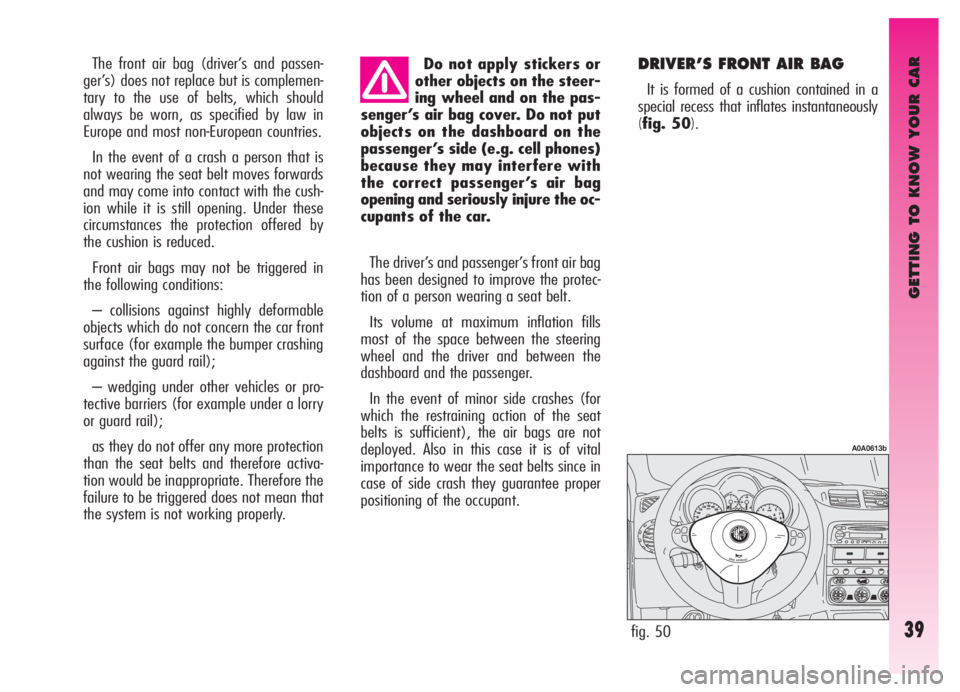
positioning of the occupant. DRIVER’S FRONT AIR BAG
It is formed of a cushion contained in a
special recess that inflates instantaneously
(fig. 50). The front air bag (driver’s and passen-
ger’s) does not replace but is complemen-
tary to the use of belts, which should
always be worn, as specified by law in
Europe and most non-European countries.
In the event of a crash a person that is
not wearing the seat belt moves forwards
and may come into contact with the cush-
ion while it is still opening. Under these
circumstances the protection offered by
the cushion is reduced.
Front air bags may not be triggered in
the following conditions:
– collisions against highly deformable
objects which do not concern the car front
surface (for example the bumper crashing
against the guard rail);
– wedging under other vehicles or pro-
tective barriers (for example under a lorry
or guard rail);
as they do not offer any more protection
than the seat belts and therefore activa-
tion would be inappropriate. Therefore the
failure to be triggered does not mean that
the system is not working properly.
fig. 50
A0A0613b
Page 42 of 307
GETTING TO KNOW YOUR CAR
40
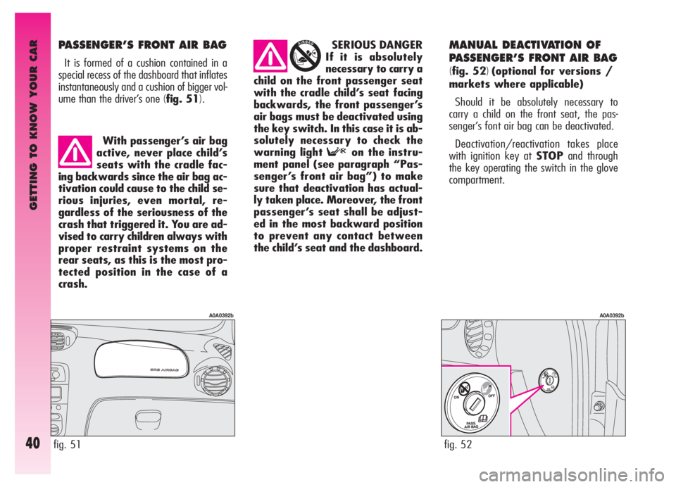
PASSENGER’S FRONT AIR BAG
It is formed of a cushion contained in a
special recess of the dashboard that inflates
instantaneously and a cushion of bigger vol-
ume than the driver’s one
(fig. 51).
MANUAL DEACTIVATION OF
PASSENGER’S FRONT AIR BAG
(
fig. 52)(optional for versions /
markets where applicable)
Should it be absolutely necessary to
carry a child on the front seat, the pas-
senger’s font air bag can be deactivated.
Deactivation/reactivation takes place
with ignition key at STOPand through
the key operating the switch in the glove
compartment. SERIOUS DANGER
If it is absolutely
necessary to carry a
child on the front passenger seat
with the cradle child’s seat facing
backwards, the front passenger’s
air bags must be deactivated using
the key switch. In this case it is ab-
solutely necessary to check the
warning light Fon the instru-
ment panel (see paragraph “Pas-
senger’s front air bag”) to make
sure that deactivation has actual-
ly taken place. Moreover, the front
passenger’s seat shall be adjust-
ed in the most backward position
to prevent any contact between
the child’s seat and the dashboard.
fig. 51
A0A0392b
fig. 52
A0A0392b
With passenger’s air bag
active, never place child’s
seats with the cradle fac-
ing backwards since the air bag ac-
tivation could cause to the child se-
rious injuries, even mortal, re-
gardless of the seriousness of the
crash that triggered it. You are ad-
vised to carry children always with
proper restraint systems on the
rear seats, as this is the most pro-
tected position in the case of a
crash.
Page 46 of 307
GETTING TO KNOW YOUR CAR
44
STEERING WHEEL
LEVERS
The devices and services controlled by
the levers on the steering wheel can only
be activated with the ignition key at
MAR.
LEFT-HAND LEVER
The left-hand lever controls the outer
lights except for the fog lamps and rear
fog guards.
When the outer lights are switched on,
the various controls on the dashboard are
illuminated.
Only with the ignition key at PARK,
regardless of the position of the knurled
ring, the sidelights and number plate
lights stay on.
Position (1or2-fig. 60) of the lever
causes the turning on only of the side-
lights (front and rear), on the right or left
respectively.
Lights switched off(fig. 55)
When the pointer in the knurled ring is
opposite the symbol O, the outer lights
are switched off. Turning the ignition key to
MAR, the
Fwarning light
(with the passenger’s front
air bag deactivation switch at ON)
turns on and flashes for a few sec-
onds to remind that the passen-
ger’s air bag will be activated in
the event of a crash, then it goes
off.The front air bags are de-
signed to be triggered for
heavier crashes than the
pretensioners. It is therefore nor-
mal for the pretensioners only to
be triggered for crashes within the
two activation thresholds.
Do not hook rigid objects
to the coat hooks and to
the support handles.
The air bag does not re-
place the seat belts, but in-
creases their effectiveness.
Additionally, as the front air bags
are not triggered for head-on-col-
lision at low speed, side crashes,
crashes from behind or overturn-
ing, in these cases the occupants
are protected only by the seat
belts, which must, therefore, al-
ways be fastened. Do not wash the seat
back with pressurised wa-
ter or steam (by hand or at
automatic seat washing stations).
Page 47 of 307

GETTING TO KNOW YOUR CAR
45
Sidelights(fig. 56)
The sidelights are switched on by turning
the knurled ring from Oto
6.
The
3warning light on the instrument
cluster will come on at the same time.
Dipped-beam headlights (fig. 57)
These are switched on by turning the
knurled ring from
6to2.
fig. 55
A0A0063b
fig. 56
A0A0064b
Main beams (fig. 58)
To turn the main beams on, set the
knurled ring to position
2and push the
lever towards the dashboard (stable posi-
tion); warning light
1on the instrument
panel will turn on.
To set dipped-beams back pull the lever
towards the steering wheel.
fig. 57
A0A0065b
fig. 58
A0A0066b
When the dipped beam headlights and
the fog lamps are switched on, the outer
light control unit (integrated in the Body
Computer) works according to the follow-
ing logics:
– turning on the main beams, the
dipped beams turn off while the fog lamps
stay on, when restoring the starting con-
dition at dipped beam setting;
or
– turning on the main beams, the fog
lamps turn off and then turn on again
automatically as the main beams are
switched off.
Therefore, in the event of Body
Computer replacement, the outer light
operating logic may be different.
fig. 59
A0A0067b