sensor Alfa Romeo GT 2005 Owner handbook (in English)
[x] Cancel search | Manufacturer: ALFA ROMEO, Model Year: 2005, Model line: GT, Model: Alfa Romeo GT 2005Pages: 307, PDF Size: 6.05 MB
Page 10 of 307
GETTING TO KNOW YOUR CAR
8
The button B should only
be pressed when the key is
away from the body, in
particular from the eyes, and from
objects that can be spoilt (clothes
for instance). Make sure the key
can never be touched by others, es-
pecially children, who may inad-
vertently press the button.
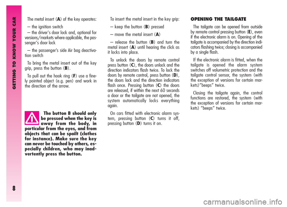
OPENING THE TAILGATE
The tailgate can be opened from outside
by remote control pressing button (E), even
if the electronic alarm is on. Opening of the
tailgate is accompanied by the direction indi-
cators flashing twice; closing is accompanied
by a single flash.
If the electronic alarm is fitted, when the
tailgate is opened the alarm system
switches off volumetric protection and the
tailgate control sensor, the system (with
the exception of versions for certain mar-
kets)”beeps” twice.
Closing the tailgate again, the control
functions are restored, the system (with
the exception of versions for certain mar-
kets) “beeps” twice. The metal insert (A) of the key operates:
– the ignition switch
– the driver's door lock and, optional for
versions/markets where applicable, the pas-
senger's door lock
– the passenger’s side Air bag deactiva-
tion switch
To bring the metal insert out of the key
grip, press the button (B).
To pull out the hook ring (F) use a fine-
ly pointed object (e.g. pen) and work in
the direction of the arrow.
To insert the metal insert in the key grip:
– keep the button (B) pressed
– move the metal insert (A)
– release the button (B) and turn the
metal insert (A) until hearing the click as
it locks into place.
To unlock the doors by remote control
press button (C), the doors unlock and the
direction indicators flash twice. To lock the
doors by remote control, press button (D),
the doors lock and the direction indicators
flash once. Pressing button (C) the doors
are released, if within the next 60 seconds
a door or the tailgate are not opened, the
system automatically locks everything
again.
On cars fitted with electronic alarm sys-
tem, pressing button (C) turns it off,
pressing button (D) turns it on.
Page 13 of 307
GETTING TO KNOW YOUR CAR
11
ELECTRONIC ALARM
DESCRIPTION
The system comprises: a transmitter,
receiver, control unit with siren and volu-
metric sensors. The electronic alarm is
controlled by the receiver incorporated in
the instrument cluster and it is turned on
and off by the remote control in the key
which sends the crypted and variable
code. The electronic alarm controls: the
unlawful opening of doors, bonnet and
boot (perimetral protection), operation of
the ignition key, battery cable cutting, the
presence of moving bodies in the passen-
ger compartment (volumetric protection),
any abnormal raising/sloping of the car
(for versions/markets where applicable)
and central door locking. It also makes it
possible to cut off the volumetric protec-
tion.
IMPORTANTThe engine inhibitor
function is guaranteed by the Alfa Romeo
CODE system which is activated automati-
cally when the ignition key is removed.The remote control is incorporated in the
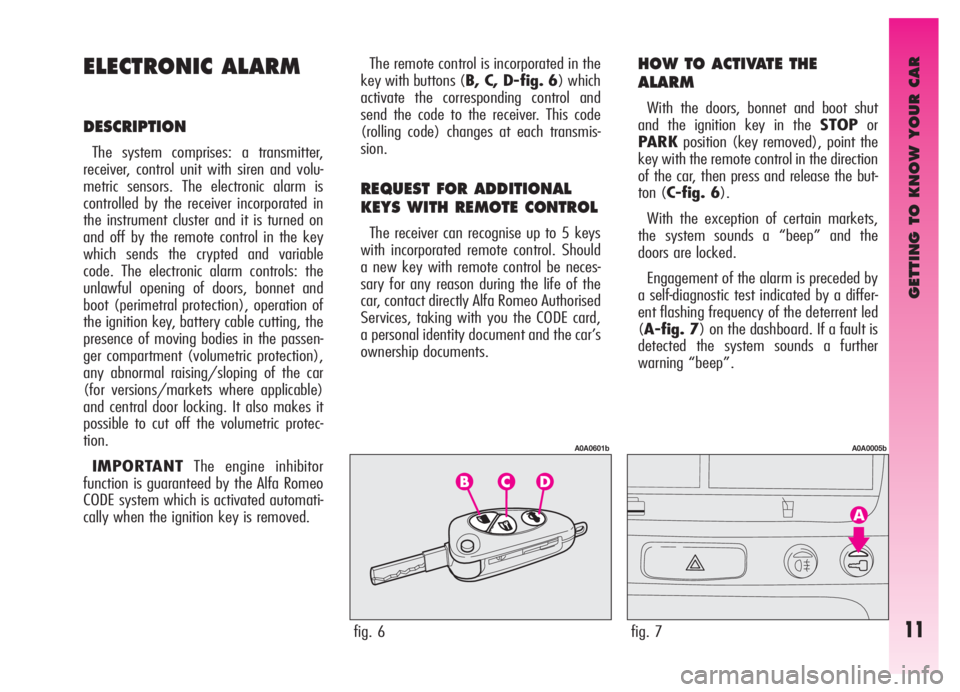
key with buttons (B, C, D-fig. 6) which
activate the corresponding control and
send the code to the receiver. This code
(rolling code) changes at each transmis-
sion.
REQUEST FOR ADDITIONAL
KEYS WITH REMOTE CONTROL
The receiver can recognise up to 5 keys
with incorporated remote control. Should
a new key with remote control be neces-
sary for any reason during the life of the
car, contact directly Alfa Romeo Authorised
Services, taking with you the CODE card,
a personal identity document and the car’s
ownership documents.
HOW TO ACTIVATE THE
ALARM
With the doors, bonnet and boot shut
and the ignition key in the STOPor
PARKposition (key removed), point the
key with the remote control in the direction
of the car, then press and release the but-
ton (C-fig. 6).
With the exception of certain markets,
the system sounds a “beep” and the
doors are locked.
Engagement of the alarm is preceded by
a self-diagnostic test indicated by a differ-
ent flashing frequency of the deterrent led
(A-fig. 7) on the dashboard. If a fault is
detected the system sounds a further
warning “beep”.
fig. 6
A0A0601b
fig. 7
A0A0005b
Page 30 of 307

GETTING TO KNOW YOUR CAR
28
Rear seat belts shall be worn according
to the diagram illustrated in (fig. 38).
(Fig. 39) shows the incorrect seat belt
fastening operation. To tilt the back rest,
see the paragraph “Extending the luggage
compartment”.
IMPORTANTRemember that, in the
event of an accident, any passengers
occupying the rear seats who are not
wearing a seat belt not only subject them-
selves to great personal risk, but consti-
tute a danger to the occupants of the front
seats.PRE-TENSIONING DEVICES
To increase the efficiency of the front
seat belts, the car is fitted with pre-ten-
sioning devices. These devices “feel” that
the car is being subject to a violent impact
by way of a sensor and rewind the seat
belts a few centimetres. In this way they
ensure that the seat belt adheres to the
wearer before the restraining action
begins.
The seat belt locks to indicate that the
device has intervened; the seat belt can-
not be drawn back up even when guiding
it manually.
IMPORTANTThe pretensioner will
give maximum protection when the seat
belt adheres snugly to wearer’s chest and
hips.
fig. 39
A0A0387b
fig. 38
A0A0386b
Front seat pretensioners activate only if
front seat belts are properly fitted into the
buckles.
A small amount of smoke may be pro-
duced. This smoke is in no way toxic and
presents no fire hazard.
The emergency tensioning retractor
needs no maintenance or lubrication. Any
modification to its original features will
nullify the retractor effectiveness. If, due
to unusual natural events (floods, high
waves, etc.), the device has been affect-
ed by water and mud, it must be replaced.
Page 50 of 307

GETTING TO KNOW YOUR CAR
48
At each start, the rain sensor automati-
cally stabilises at a temperature of about
40°C to eliminate any condensation from
the control surface and prevent the forma-
tion of ice.
The rain sensor is able to detect and
automatically adapt to the presence of the
following particular conditions which
require different sensitivity:
– impurities on the control surface (salt,
dirt, etc.);
– streaks of water caused by worn wiper
blades;
– difference between day and night (the
human eye is more disturbed during the
night by the wet glass surface). Rain sensor(fig. 64)
The rain sensor (A), fitted only on cer-
tain versions, is an electronic device com-
bined with the windscreen wiper which
has the purpose of automatically adjusting
the number of wipes during intermittent
operation to the intensity of the rain.
All the other functions controlled by the
right-hand lever remain unchanged.
The rain sensor is activated automatical-
ly moving the right-hand lever to position
(B-fig. 62) and it has a range of adjust-
ment that gradually varies between wiper
stationary (no wiping) when the wind-
screen is dry, to wiper at first continuous
speed (continuous, slow) with heavy rain.Turning the knurled ring (F-fig. 62) it
is possible to increase the sensitivity of the
rain sensor, obtaining a quicker change
from stationary, when the windscreen is
dry, to first continuous speed (continuous,
slow).
Operating the windscreen washer with
the rain sensor activated (lever at position
B) the normal washing cycle is performed
at the end of which the rain sensor
resumes its normal automatic function.
Turning the ignition key to STOPthe
rain sensor is deactivated and the next
time the engine is started (MAR posi-
tion) it will not be reactivated even if the
lever has remained in position (B). In this
case to activate the rain sensor, simply
move the lever to (A) or (C) and then
back to (B).
When the rain sensor is reactivated in
this way, the wiper performs at least one
stroke, even if the windscreen is dry, to
indicate that reactivation has occurred.
The rain sensor is located behind the
inner rear-view mirror in contact with the
windscreen and inside the area cleaned by
the wiper and it controls an electronic con-
trol unit which in turn controls the wiper
motor.
fig. 64
A0A0331b
Page 54 of 307
GETTING TO KNOW YOUR CAR
52
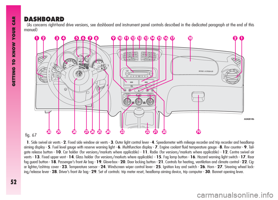
DASHBOARD
(As concerns right-hand drive versions, see dashboard and instrument panel controls described in the dedicated paragraph at the end of this
manual)
1. Side swivel air vents - 2. Fixed side window air vents - 3. Outer light control lever - 4. Speedometer with mileage recorder and trip recorder and headlamp
aiming display - 5. Fuel level gauge with reserve warning light - 6. Multifunction display - 7. Engine coolant fluid temperature gauge - 8. Rev counter - 9. Tail-
gate release button - 10. Car holder (for versions/markets where applicable) - 11. Radio (for versions/markets where applicable) - 12. Centre swivel air
vents - 13. Fixed upper vent - 14. Glass holder (for versions/markets where applicable) - 15. Fog lamp button - 16. Hazard warning light switch - 17. Rear
fog guard button - 18. Passenger’s front Air bag - 19. Glove-box - 20. Door locking button - 21. Controls for heating, ventilation and climate control - 22. Cig-
ar lighter/ashtray cover - 23. Temperature sensor - 24. Windscreen wiper control lever - 25. Ignition key and switch - 26. Horn - 27. Steering wheel lock-
ing/release lever - 28. Driver’s front Air bag - 29. Set of controls: trip meter reset, headlamp aiming device, trip computer - 30. Bonnet opening lever.
fig. 67
A0A0618b
Page 91 of 307
GETTING TO KNOW YOUR CAR
89
Warning
light on dialMessage
on display
d
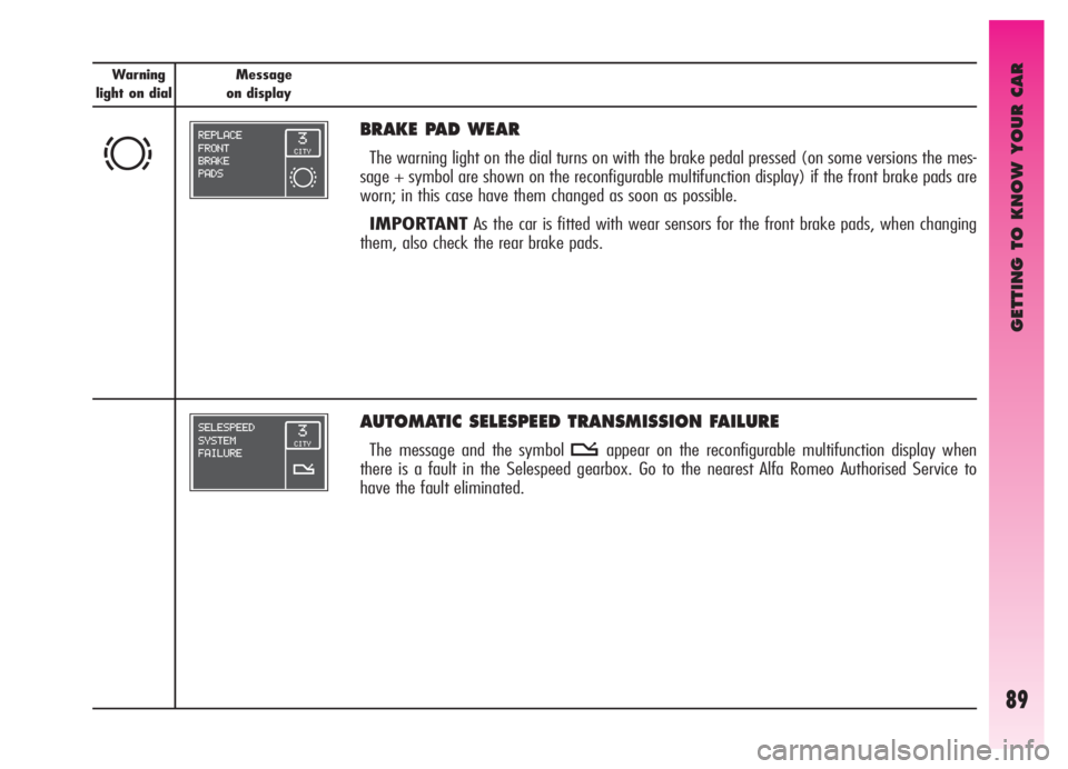
BRAKE PAD WEAR
The warning light on the dial turns on with the brake pedal pressed (on some versions the mes-
sage + symbol are shown on the reconfigurable multifunction display) if the front brake pads are
worn; in this case have them changed as soon as possible.
IMPORTANTAs the car is fitted with wear sensors for the front brake pads, when changing
them, also check the rear brake pads.
AUTOMATIC SELESPEED TRANSMISSION FAILURE
The message and the symbol tappear on the reconfigurable multifunction display when
there is a fault in the Selespeed gearbox. Go to the nearest Alfa Romeo Authorised Service to
have the fault eliminated.
Page 95 of 307
GETTING TO KNOW YOUR CAR
93
Warning
light on dialMessage
on display
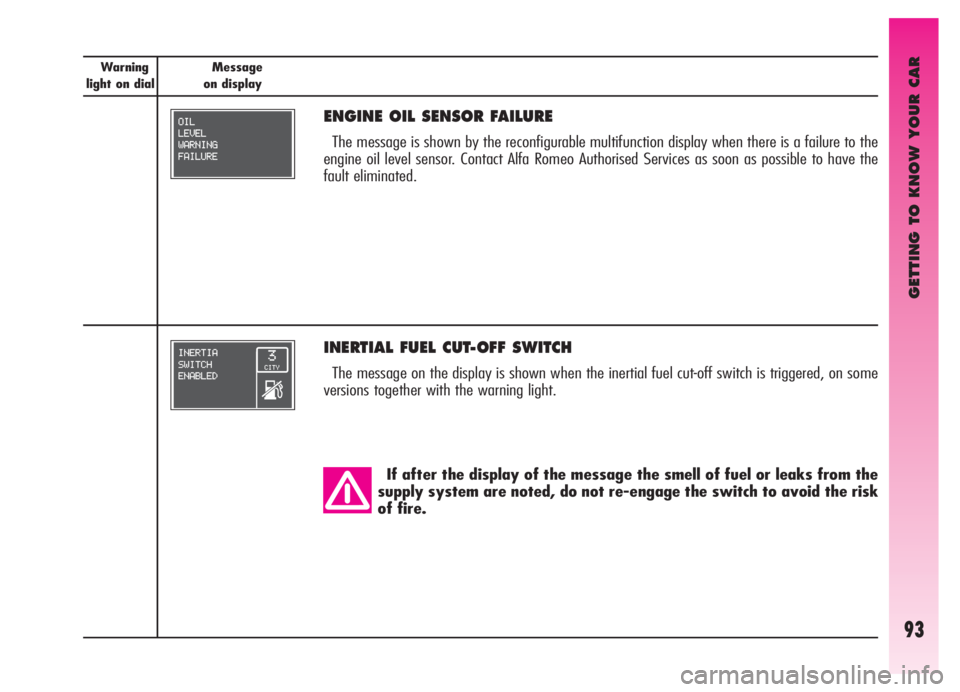
INERTIAL FUEL CUT-OFF SWITCH
The message on the display is shown when the inertial fuel cut-off switch is triggered, on some
versions together with the warning light.
If after the display of the message the smell of fuel or leaks from the
supply system are noted, do not re-engage the switch to avoid the risk
of fire.
ENGINE OIL SENSOR FAILURE
The message is shown by the reconfigurable multifunction display when there is a failure to the
engine oil level sensor. Contact Alfa Romeo Authorised Services as soon as possible to have the
fault eliminated.
Page 110 of 307
GETTING TO KNOW YOUR CAR
108
AUTOMATIC TWO-ZONE CLIMATE CONTROL SYSTEM
(for versions/markets where applicable)
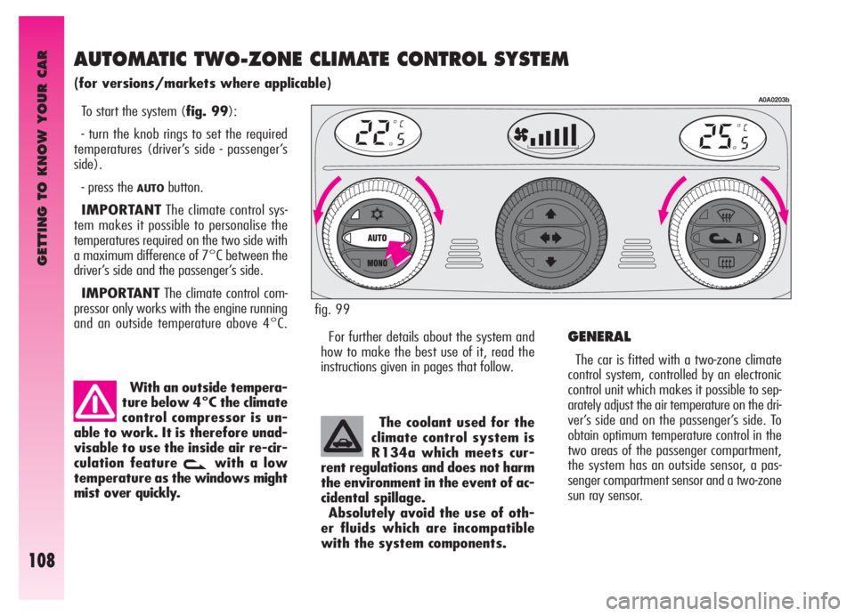
To start the system (fig. 99):
- turn the knob rings to set the required
temperatures (driver’s side - passenger’s
side).
- press the
AUTObutton.
IMPORTANTThe climate control sys-
tem makes it possible to personalise the
temperatures required on the two side with
a maximum difference of 7°C between the
driver’s side and the passenger’s side.
IMPORTANTThe climate control com-
pressor only works with the engine running
and an outside temperature above 4°C.
With an outside tempera-
ture below 4°C the climate
control compressor is un-
able to work. It is therefore unad-
visable to use the inside air re-cir-
culation feature
vwith a low
temperature as the windows might
mist over quickly.
For further details about the system and
how to make the best use of it, read the
instructions given in pages that follow.
A0A0203b
fig. 99
The coolant used for the
climate control system is
R134a which meets cur-
rent regulations and does not harm
the environment in the event of ac-
cidental spillage.
Absolutely avoid the use of oth-
er fluids which are incompatible
with the system components.
GENERAL
The car is fitted with a two-zone climate
control system, controlled by an electronic
control unit which makes it possible to sep-
arately adjust the air temperature on the dri-
ver’s side and on the passenger’s side. To
obtain optimum temperature control in the
two areas of the passenger compartment,
the system has an outside sensor, a pas-
senger compartment sensor and a two-zone
sun ray sensor.
Page 111 of 307

GETTING TO KNOW YOUR CAR
109
- temperature of the air admitted to the
passenger compartment (for the driver’s and
passenger’s side separately)
- fan speed
- air distribution
- inside air re-circulation on/off
- climate control compressor on/off en-
able.
It is possible to change the setting of the
following functions manually:
- fan speed
- air distribution
- inside air re-circulation on/off
- climate control compressor on/off en-
able.
The control of functions not changed man-
ually remains automatic and in any case the
temperature of the air admitted to the pas-
senger compartment is controlled automati-
cally according to the temperatures set on
the driver’s and passenger’s displays.
IMPORTANTManual selections prevail
over automatic ones and remain in storage
until the user decides to resume automatic
control. The settings selected manually are
stored when the engine is switched off and
resumed the next time it is started. To ensure correct opera-
tion of the incipient mist-
ing sensor, stickers must
not be applied (road licence holder,
time card etc.). Care should also be
given to cleaning the windscreen
and the actual sensor, avoiding the
accumulation of dust and other sub-
stances.IMPORTANTThe demisting procedure
is enabled each time the ignition key is
turned to MARor pressing the
AUTObut-
ton. When this procedure is working it can
be turned off pressing one of the following
buttons: compressor, air recirculation, air
flow, air capacity. This operation inhibits the
incipient misting sensor signal until the
AUTObutton is pressed again or the next
time the ignition key is turned toMAR.
On certain versions, the system is inte-
grated by an antipollution sensor capable of
automatically switching on inside air re-cir-
culation to lessen the harmful effects of pol-
luted air in cities, queues, tunnels and op-
eration of the windscreen washer (with the
typical smell of spirit).
IMPORTANTThe function of the an-
tipollution sensor is subordinate to safety
conditions; therefore disabling the climate
control compressor or at an outside tem-
perature below 4°C the sensor is disabled.
The sensor can be re-enabled pressing the
re-circulation button
vuntil taking it to
the automatic mode.
Air quality control is also entrusted to a
combined particle and activated carbon fil-
ter. The climate control system automatically
controls and adjusts the following parame-
ters and functions: On some versions the system is integrat-
ed with an incipient misting sensor installed
behind the inside rear-view mirror, capable
of “controlling” a predefined area of the
windscreen inner surface which can auto-
matically act on the system to prevent or re-
duce misting through a series of operations
such as: opening air re-circulation, enabling
the compressor, air flow to the windscreen,
fan speed sufficient for demisting; in the
case of heavy misting, enabling the
MAX-
DEFfunction.
Page 112 of 307
GETTING TO KNOW YOUR CAR
110
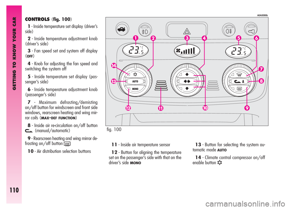
CONTROLS(fig. 100)
1- Inside temperature set display (driver’s
side)
2- Inside temperature adjustment knob
(driver’s side)
3- Fan speed set and system off display
(
OFF)
4- Knob for adjusting the fan speed and
switching the system off
5- Inside temperature set display (pas-
senger’s side)
6- Inside temperature adjustment knob
(passenger’s side)
7- Maximum defrosting/demisting
on/off button for windscreen and front side
windows, rearscreen heating and wing mir-
ror coils (
MAX-DEF FUNCTION)
8- Inside air re-circulation on/off button
v(manual/automatic)
9- Rearscreen heating and wing mirror de-
frosting on/off button
(
10- Air distribution selection buttons11- Inside air temperature sensor
12- Button for aligning the temperature
set on the passenger’s side with that on the
driver’s side
MONO
13- Button for selecting the system au-
tomatic mode
AUTO
14- Climate control compressor on/off
enable button
√
fig. 100
A0A0090b