fog light Alfa Romeo GT 2006 Owner handbook (in English)
[x] Cancel search | Manufacturer: ALFA ROMEO, Model Year: 2006, Model line: GT, Model: Alfa Romeo GT 2006Pages: 307, PDF Size: 6.05 MB
Page 46 of 307
GETTING TO KNOW YOUR CAR
44
STEERING WHEEL
LEVERS
The devices and services controlled by
the levers on the steering wheel can only
be activated with the ignition key at
MAR.
LEFT-HAND LEVER
The left-hand lever controls the outer
lights except for the fog lamps and rear
fog guards.
When the outer lights are switched on,
the various controls on the dashboard are
illuminated.
Only with the ignition key at PARK,
regardless of the position of the knurled
ring, the sidelights and number plate
lights stay on.
Position (1or2-fig. 60) of the lever
causes the turning on only of the side-
lights (front and rear), on the right or left
respectively.
Lights switched off(fig. 55)
When the pointer in the knurled ring is
opposite the symbol O, the outer lights
are switched off. Turning the ignition key to
MAR, the
Fwarning light
(with the passenger’s front
air bag deactivation switch at ON)
turns on and flashes for a few sec-
onds to remind that the passen-
ger’s air bag will be activated in
the event of a crash, then it goes
off.The front air bags are de-
signed to be triggered for
heavier crashes than the
pretensioners. It is therefore nor-
mal for the pretensioners only to
be triggered for crashes within the
two activation thresholds.
Do not hook rigid objects
to the coat hooks and to
the support handles.
The air bag does not re-
place the seat belts, but in-
creases their effectiveness.
Additionally, as the front air bags
are not triggered for head-on-col-
lision at low speed, side crashes,
crashes from behind or overturn-
ing, in these cases the occupants
are protected only by the seat
belts, which must, therefore, al-
ways be fastened. Do not wash the seat
back with pressurised wa-
ter or steam (by hand or at
automatic seat washing stations).
Page 47 of 307

GETTING TO KNOW YOUR CAR
45
Sidelights(fig. 56)
The sidelights are switched on by turning
the knurled ring from Oto
6.
The
3warning light on the instrument
cluster will come on at the same time.
Dipped-beam headlights (fig. 57)
These are switched on by turning the
knurled ring from
6to2.
fig. 55
A0A0063b
fig. 56
A0A0064b
Main beams (fig. 58)
To turn the main beams on, set the
knurled ring to position
2and push the
lever towards the dashboard (stable posi-
tion); warning light
1on the instrument
panel will turn on.
To set dipped-beams back pull the lever
towards the steering wheel.
fig. 57
A0A0065b
fig. 58
A0A0066b
When the dipped beam headlights and
the fog lamps are switched on, the outer
light control unit (integrated in the Body
Computer) works according to the follow-
ing logics:
– turning on the main beams, the
dipped beams turn off while the fog lamps
stay on, when restoring the starting con-
dition at dipped beam setting;
or
– turning on the main beams, the fog
lamps turn off and then turn on again
automatically as the main beams are
switched off.
Therefore, in the event of Body
Computer replacement, the outer light
operating logic may be different.
fig. 59
A0A0067b
Page 54 of 307
GETTING TO KNOW YOUR CAR
52
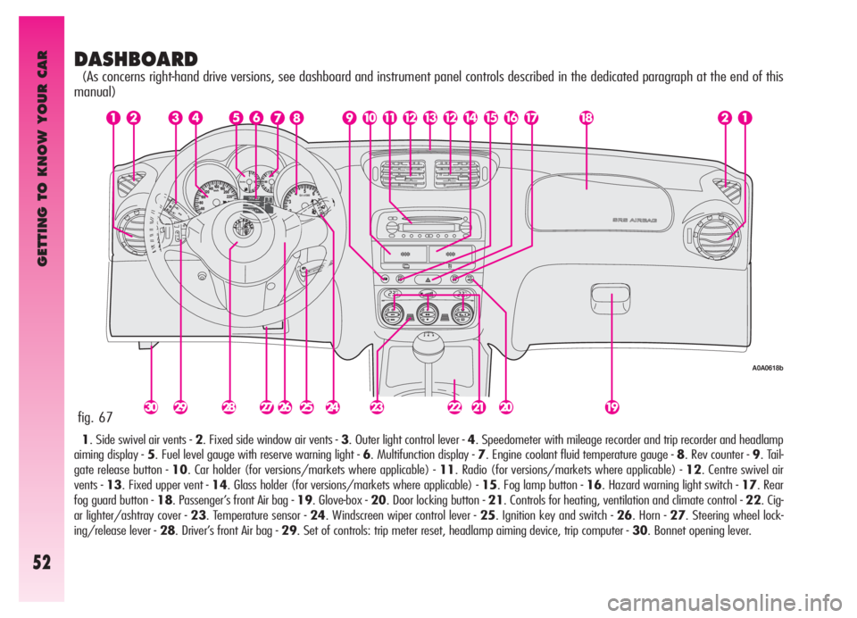
DASHBOARD
(As concerns right-hand drive versions, see dashboard and instrument panel controls described in the dedicated paragraph at the end of this
manual)
1. Side swivel air vents - 2. Fixed side window air vents - 3. Outer light control lever - 4. Speedometer with mileage recorder and trip recorder and headlamp
aiming display - 5. Fuel level gauge with reserve warning light - 6. Multifunction display - 7. Engine coolant fluid temperature gauge - 8. Rev counter - 9. Tail-
gate release button - 10. Car holder (for versions/markets where applicable) - 11. Radio (for versions/markets where applicable) - 12. Centre swivel air
vents - 13. Fixed upper vent - 14. Glass holder (for versions/markets where applicable) - 15. Fog lamp button - 16. Hazard warning light switch - 17. Rear
fog guard button - 18. Passenger’s front Air bag - 19. Glove-box - 20. Door locking button - 21. Controls for heating, ventilation and climate control - 22. Cig-
ar lighter/ashtray cover - 23. Temperature sensor - 24. Windscreen wiper control lever - 25. Ignition key and switch - 26. Horn - 27. Steering wheel lock-
ing/release lever - 28. Driver’s front Air bag - 29. Set of controls: trip meter reset, headlamp aiming device, trip computer - 30. Bonnet opening lever.
fig. 67
A0A0618b
Page 98 of 307
GETTING TO KNOW YOUR CAR
96
Warning
light on dialMessage
on display
W
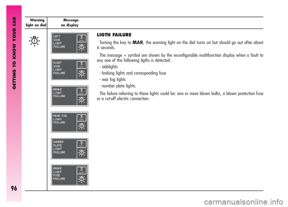
LIGTH FAILURE
Turning the key to MAR, the warning light on the dial turns on but should go out after about
6 seconds.
The message + symbol are shown by the reconfigurable multifunction display when a fault to
any one of the following ligths is detected:
- sidelights
- braking lights and corresponding fuse
- rear fog lights
- number plate lights.
The failure referring to these lights could be: one or more blown bulbs, a blown protection fuse
or a cut-off electric connection.
Page 126 of 307
GETTING TO KNOW YOUR CAR
124
CONTROLS
TAILGATE OPENING (fig. 114)
Electric tailgate release is only allowed with
the ignition key in the ignition switch at
MARvehicle stationary, at STOPor
PARK for 3 minutes without opening/clos-
ing a door. To release the tailgate, press but-
ton (A) on the centre console panel.
Use the hazard warning
lights in compliance with
local regulations.
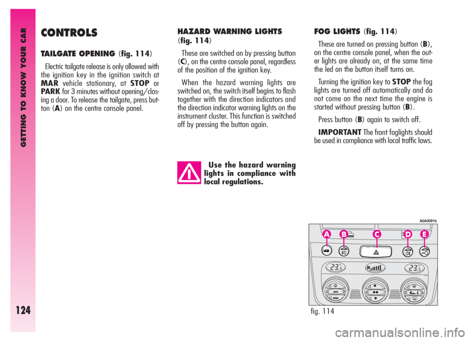
FOG LIGHTS (fig. 114)
These are turned on pressing button (B),
on the centre console panel, when the out-
er lights are already on, at the same time
the led on the button itself turns on.
Turning the ignition key to STOPthe fog
lights are turned off automatically and do
not come on the next time the engine is
started without pressing button (B).
Press button (B) again to switch off.
IMPORTANTThe front foglights should
be used in compliance with local traffic laws.
fig. 114
A0A0091b
HAZARD WARNING LIGHTS
(fig. 114)
These are switched on by pressing button
(C), on the centre console panel, regardless
of the position of the ignition key.
When the hazard warning lights are
switched on, the switch itself begins to flash
together with the direction indicators and
the direction indicator warning lights on the
instrument cluster. This function is switched
off by pressing the button again.
Page 127 of 307
GETTING TO KNOW YOUR CAR
125
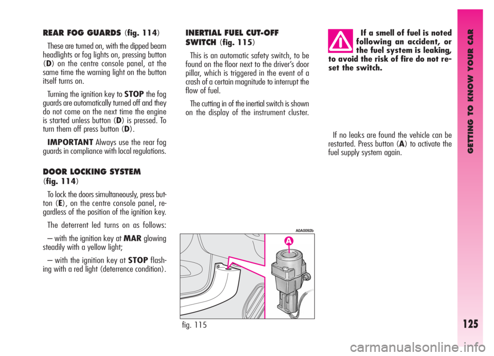
If no leaks are found the vehicle can be
restarted. Press button (A) to activate the
fuel supply system again.
fig. 115
A0A0092b
If a smell of fuel is noted
following an accident, or
the fuel system is leaking,
to avoid the risk of fire do not re-
set the switch.REAR FOG GUARDS (fig. 114)
These are turned on, with the dipped beam
headlights or fog lights on, pressing button
(D) on the centre console panel, at the
same time the warning light on the button
itself turns on.
Turning the ignition key to STOPthe fog
guards are automatically turned off and they
do not come on the next time the engine
is started unless button (D) is pressed. To
turn them off press button (D).
IMPORTANTAlways use the rear fog
guards in compliance with local regulations.
DOOR LOCKING SYSTEM
(fig. 114)
To lock the doors simultaneously, press but-
ton (E), on the centre console panel, re-
gardless of the position of the ignition key.
The deterrent led turns on as follows:
– with the ignition key at MARglowing
steadily with a yellow light;
– with the ignition key at STOPflash-
ing with a red light (deterrence condition).
INERTIAL FUEL CUT-OFF
SWITCH
(fig. 115)
This is an automatic safety switch, to be
found on the floor next to the driver’s door
pillar, which is triggered in the event of a
crash of a certain magnitude to interrupt the
flow of fuel.
The cutting in of the inertial switch is shown
on the display of the instrument cluster.
Page 227 of 307
IN AN EMERGENCY
225
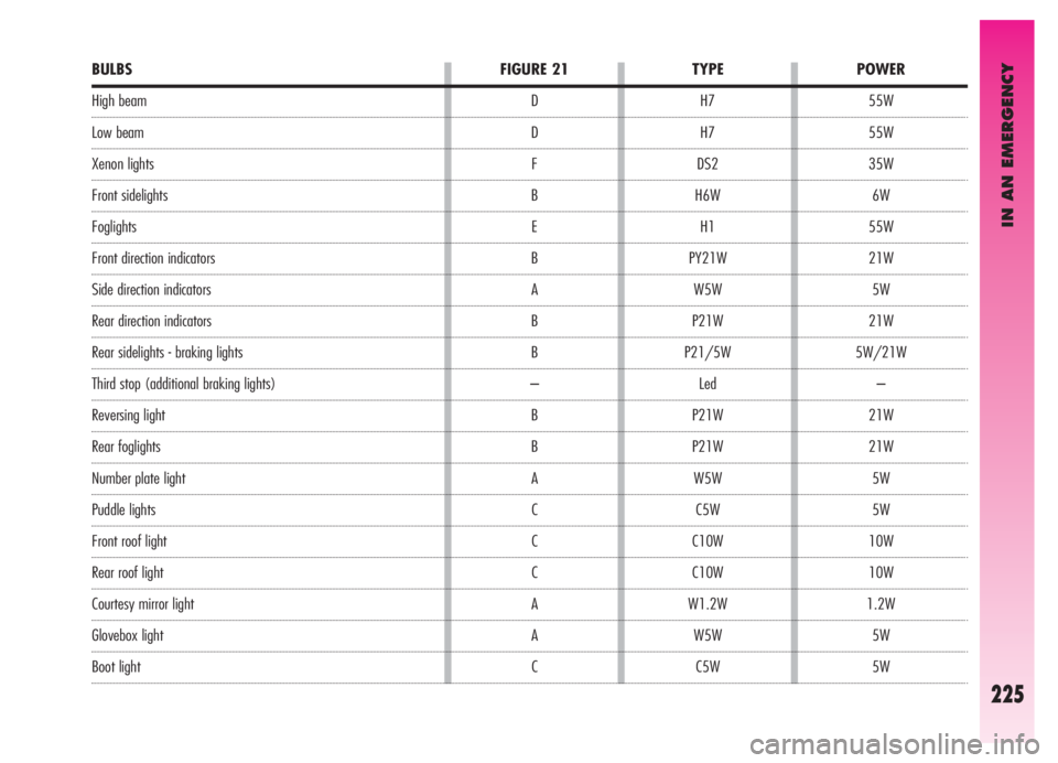
BULBS
High beam
Low beam
Xenon lights
Front sidelights
Foglights
Front direction indicators
Side direction indicators
Rear direction indicators
Rear sidelights - braking lights
Third stop (additional braking lights)
Reversing light
Rear foglights
Number plate light
Puddle lights
Front roof light
Rear roof light
Courtesy mirror light
Glovebox light
Boot lightFIGURE 21
D
D
F
B
E
B
A
B
B
–
B
B
A
C
C
C
A
A
CPOWER
55W
55W
35W
6W
55W
21W
5W
21W
5W/21W
–
21W
21W
5W
5W
10W
10W
1.2W
5W
5W TYPE
H7
H7
DS2
H6W
H1
PY21W
W5W
P21W
P21/5W
Led
P21W
P21W
W5W
C5W
C10W
C10W
W1.2W
W5W
C5W
Page 228 of 307
IN AN EMERGENCY
226
IF AN EXTERIOR
LIGHT GOES OUT
XENON LIGHTS
Due to high voltage, the
bulb of (Xenon) gas-dis-
charge headlights must on-
ly be replaced by experts: danger
of death! Contact Alfa Romeo Au-
thorized Services.
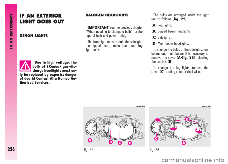
HALOGEN HEADLIGHTSThe bulbs are arranged inside the light
unit as follows (fig. 22):
(A) Fog lights.
(B) Dipped beam headlights.
(C) Sidelights.
(D) Main beam headlights.
To change the bulbs of the sidelights, low
beams and main beams it is necessary to
remove the cover (A-fig. 23) releasing
the catches (B).
To change the fog lights, remove the
cover (C) turning counter-clockwise. IMPORTANTSee the previous chapter
“When needing to change a bulb” for the
type of bulb and power rating.
The front light units contain the sidelight,
the dipped beam, main beam and fog
light bulbs.
fig. 22
A0A0159b
fig. 23
A0A0160b
Page 229 of 307

IN AN EMERGENCY
227
– Fit a new bulb, making the tab of the
metal part coincide with the one on the
lamp unit, then hook the bulb holder catch
(B).
– Re-connect the electric connector (A).
– Refit the protective cover correctly.Fog lights (fig. 24)
IMPORTANTWhen needing to
change the left bulb, the side trim next to
the light itself needs to be removed to
facilitate access to the engine compart-
ment.
To change the bulb, proceed as follows:
– Remove the protective cover turning
counter-clockwise.
– Disconnect the electric connector (A).
– Release the bulb catch (B).
– Remove the bulb and replace it.
fig. 24
A0A0161b
After replacement, refit
the covers correctly
checking that they are
properly secured.
IMPORTANTA slight layer of steam
(fogging) can appear on the inside surface
of the beam transparent cover: this is not
a defect. The presence of condensate
traces in beams is a natural phenomenon,
due to a low temperature and to the
degree of humidity in the air. These traces
will disappear when the beams are turned
on. Drops of water inside the headlight
indicate instead water infiltration: contact
Alfa Romeo Authorised Services.
Page 232 of 307

IN AN EMERGENCY
230
REVERSING LIGHT
AND REAR FOG GUARDS
(fig. 31-32)
The reversing light and rear fog guard are
in the tail light unit fastened to the tailgate;
they are to be found respectively one on the
right and the other on the left of the vehicle
facing forwards.
To change the bulb, proceed as follows:
– from the bumper lower side (fig. 31),
operate on the bulb holder (A-fig 32) turn-
ing it counter-clockwise and remove it. Take
care not to get burnt if the muffler is still hot;
fig. 31
A0A0627b
fig. 33
A0A0629b
– Remove the bulb pushing gently and
turning counter-clockwise;
– Replace the bulb, then refit the bulb
holder.
Anyway, you are advised to have this
operation carried out by Alfa Romeo
Authorised Services.REAR DIRECTION INDICATORS
AND REAR SIDELIGHTS-
BRAKING LIGHTS
(fig. 33-34)
The rear direction indicators and the side-
lights-braking lights are in the tail light
unit fastened to the body.
To change the bulb, proceed as follows:
– From inside the boot, open the com-
partment (A-fig. 33) and then the door
(B) through the tab (C);
– Turn the bulb for sidelight and braking
light counter-clockwise (D-fig. 34),
or the bulb for the direction indicator (E-
fig. 34) and remove it;
fig. 32
A0A0628b