roof Alfa Romeo GT 2006 Owner handbook (in English)
[x] Cancel search | Manufacturer: ALFA ROMEO, Model Year: 2006, Model line: GT, Model: Alfa Romeo GT 2006Pages: 307, PDF Size: 6.05 MB
Page 15 of 307

GETTING TO KNOW YOUR CAR
13
WHEN THE ALARM
IS TRIGGERED
When the system is on, the alarm comes
into action in the following cases:
– opening of one of the doors, bonnet or
tailgate;
– disconnection of the battery or sec-
tioning of electric cables;
– intrusion in the passenger compart-
ment, for example breakage of windows
(volumetric protection);
– attempt to start the engine (key in
MARposition);
– abnormal car lifting/sloping (for ver-
sions/markets where applicable).
Depending on the markets, the cutting in
of the alarm causes operation of the siren
and hazard warning ligths (for about 26
seconds). The ways of operating and the
number of cycles may vary depending on
the markets.
A maximum number of cycles is howev-
er envisaged.
Once the alarm cycle has ended, the sys-
tem resumes its normal control function.
VOLUMETRIC PROTECTION
To make sure that the protection system
works correctly the side windows and sun-
roof (if fitted) must be properly shut.
The function can be cut off (if, for exam-
ple, leaving animals in the car) carrying
out the following operations in rapid suc-
cession: starting from the condition with
the ignition key at MAR, move the key
toSTOP, then immediately back to
MARand then to STOPagain, then
remove the ignition key.
The deterrent led (A-fig. 7) on the
dashboard lights up for about 2 seconds to
confirm that the function has been cut off.
To restore volumetric protection, move
the and keep the ignition key at MARfor
over 30 seconds.
If, with the volumetric protection func-
tion deactivated, an electric control con-
trolled by the ignition key at MAR(e.g.
power windows) turn the ignition key to
MAR, operate the control and move the
key to STOPin a maximum time of 30
seconds. This way volumetric protection is
not restored.
HOW TO CUT OFF
THE ALARM SYSTEM
To deactivate the alarm system com-
pletely (for instance during prolonged
inactivity of the vehicle) simply lock the
car turning the key in the lock.
MINISTERIAL CERTIFICATION
In accordance with the law in force in
each country, on the subject of radio fre-
quency, we wish to point out that for the
markets in which the transmitter needs to
be marked, the certification number is
given on the component.
Depending on the versions/markets, the
code may also be given on the transmitter
and/or on the receiver.
Page 27 of 307

GETTING TO KNOW YOUR CAR
25fig. 33
A0A0043b
fig. 34
A0A0044b
IMPORTANTThe driver’s power win-
dow is fitted with the “continuous auto-
matic operation” device for both lowering
and raising the window. A brief press on
the upper or lower part of the button will
cause it to move and continue automati-
cally: the window stops in the required
position by pressing either the upper or
lower part of the button again.
Passenger’s side (fig. 34)
The button (A) controls the passenger’s
side window.
Button and window operation is the
same as that described for the driver's
side.Do not keep the button
pressed when the window
is completely raised or
lowered.
IMPORTANTFor versions/markets
where applicable, if the car is fitted with the
safety system with crush-prevention seals,
after locking the doors, keeping the remote
control button pressed for about 2 seconds,
causes automatic closing of the windows.
The remote control button should be pressed
until the windows have completed their
stroke; releasing the button sooner, the win-
dows stop in the position they are in at that
moment.
On all versions, after unlocking the doors,
keeping the remote control button pressed
for about 2 seconds, the windows and sun-
roof (if present) are opened.Improper use of power
windows can be danger-
ous. Before and during use,
always make sure that the pas-
sengers are not exposed to the risk
of harm either directly by the mov-
ing windows or by personal objects
drawn or knocked by them.
When leaving the car, al-
ways remove the ignition
key to prevent the power
windows from being operated in-
advertently, and harming anyone
left on board.
Page 43 of 307

GETTING TO KNOW YOUR CAR
41
The key can be inserted and removed in
both positions.
IMPORTANTUse the switch only with
the engine off and the ignition key
removed.
The key-operated switch has two posi-
tions:
– passenger’s front air bag activated
(ONpositionP): warning light
Fon
instrument cluster off; it is absolutely pro-
hibited to carry a child on the front seat.
– passenger’s front air bag deactivated
(OFFposition
F): warning light Fon
instrument cluster on; it is possible to
carry a child protected by special restraint
systems on the front seat.
The warning light
Fon the cluster
stays on permanently until the passen-
ger’s air bag is reactivated.
Deactivation of the passenger’s front air
bag does not inhibit operation of the side
air bag.
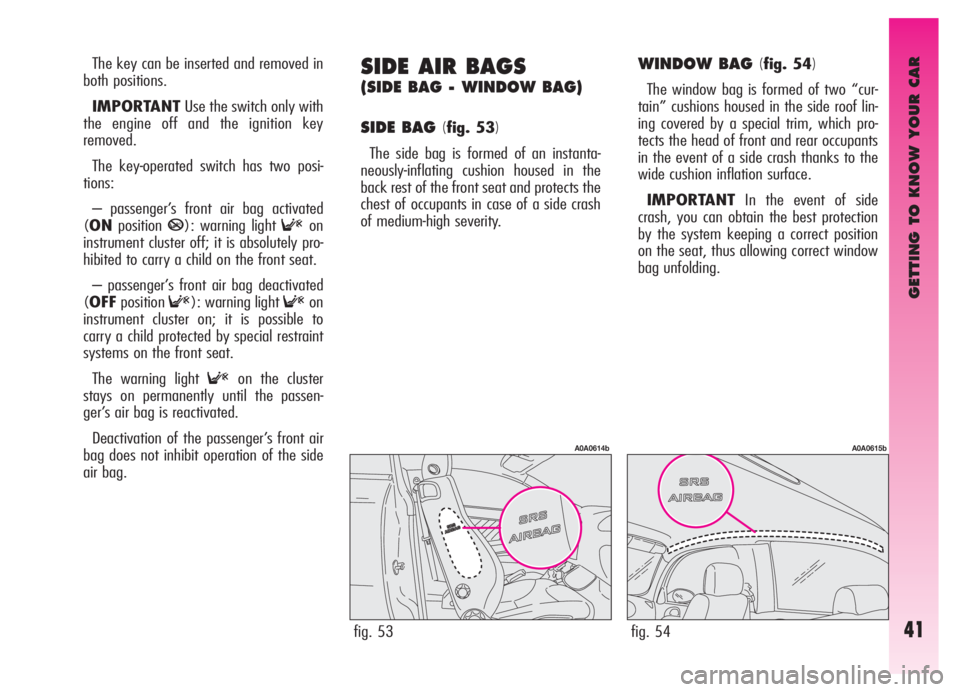
SIDE AIR BAGS
(SIDE BAG - WINDOW BAG)
SIDE BAG (
fig. 53)
The side bag is formed of an instanta-
neously-inflating cushion housed in the
back rest of the front seat and protects the
chest of occupants in case of a side crash
of medium-high severity.
WINDOW BAG (fig. 54)
The window bag is formed of two “cur-
tain” cushions housed in the side roof lin-
ing covered by a special trim, which pro-
tects the head of front and rear occupants
in the event of a side crash thanks to the
wide cushion inflation surface.
IMPORTANTIn the event of side
crash, you can obtain the best protection
by the system keeping a correct position
on the seat, thus allowing correct window
bag unfolding.
fig. 53
A0A0614b
fig. 54
A0A0615b
Page 140 of 307

GETTING TO KNOW YOUR CAR
138
INTERIOR FITTINGS
GLOVEBOX
On the dashboard there is a glovebox with
lid and light.
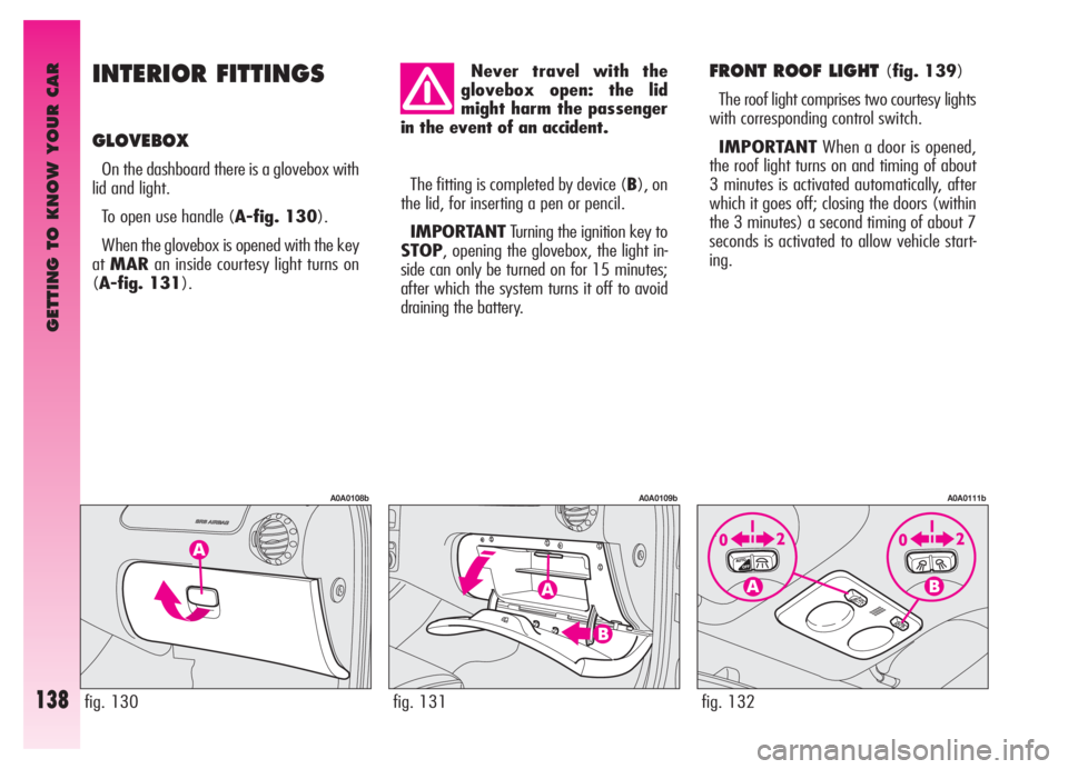
To open use handle (A-fig. 130).
When the glovebox is opened with the key
atMARan inside courtesy light turns on
(A-fig. 131).
FRONT ROOF LIGHT (fig. 139)
The roof light comprises two courtesy lights
with corresponding control switch.
IMPORTANTWhen a door is opened,
the roof light turns on and timing of about
3 minutes is activated automatically, after
which it goes off; closing the doors (within
the 3 minutes) a second timing of about 7
seconds is activated to allow vehicle start-
ing.
fig. 130
A0A0108b
fig. 131
A0A0109b
Never travel with the
glovebox open: the lid
might harm the passenger
in the event of an accident.
The fitting is completed by device (B), on
the lid, for inserting a pen or pencil.
IMPORTANTTurning the ignition key to
STOP, opening the glovebox, the light in-
side can only be turned on for 15 minutes;
after which the system turns it off to avoid
draining the battery.
fig. 132
A0A0111b
Page 141 of 307

GETTING TO KNOW YOUR CAR
139fig. 133
A0A0112b
Unlocking the doors using the remote con-
trol, the roof light turns on gradually and tim-
ing is activated automatically for about 15
seconds. Locking the doors with the remote
control the roof light turns off gradually.
The lights are turned off moving the igni-
tion key to MAR(with the doors closed).
With switch (A) in the central position
(1), both lights are turned on when a door
is opened.
Pressing switch (A) to the left (position
0), the lights stay off (OFFposition).
Pressing switch (A) to the right (position
2) both lights stay on.
Switch (B) turns the lights on individually.
Pressing switch (B) to the left (position
0) the left light is turned on. Pressing the
switch to the right (position 2) the right light
is turned on.
With switch (B) in the central position (po-
sition1) the lights stay off.IMPORTANTTurning the ignition key to
STOP, turning the roof light on is only pos-
sible for 15 minutes; after which the system
turns it off to avoid draining the battery.
IMPORTANTBefore leaving the car,
make sure that both switches are in the cen-
tral position. By so doing, the roof lights will
turn off when the doors are closed. Forget-
ting a door open the lights will turn off au-
tomatically after a few seconds.COURTESY LIGHTS (fig. 133)
On the back of the driver’s or passenger’s
sun visor, opening the cover (A) the roof
lights turn on (B) at the side of the courtesy
mirror, with the ignition key at MAR. These
lights allow use of the courtesy mirror when
the light is poor.
IMPORTANTTurning the ignition key to
STOPthe lights can be activated only for
15 minutes: after which the system turns
them off to avoid draining the battery.
Page 142 of 307

GETTING TO KNOW YOUR CAR
140
REAR ROOF LIGHT (fig. 134)
IMPORTANTWhen a door is opened,
the roof light turns on and timing of about
3 minutes is activated automatically, after
which it goes off; closing the doors (within
the 3 minutes) a second timing of about 7
seconds is activated to allow vehicle start-
ing.
Unlocking the doors using the remote con-
trol, the roof light turns on gradually and tim-
ing is activated automatically for about 15
seconds. Locking the doors with the remote
control the roof light turns off gradually.
The light turns off in any case turning the
ignition key to MAR(with the door
closed).PUDDLE LIGHTS (fig. 135)
(for versions/markets where
applicable)
The light (A) housed in the doors turns on
when the associated door is opened, re-
gardless of the position of the ignition key.
fig. 134
A0A0633b
On the light there is a switch with three
positions.
When switch (A) is in the central posi-
tion (0) the light turns on automatically
when a door is opened.
Moving the switch to the right (position 1)
the light stays off.
Moving the switch to the left (position 2)
the light stays on.
IMPORTANTTurning the ignition key to
STOPthe roof light can be turned on for on-
ly 15 minutes; after which it is turned off to
avoid draining the battery.
IMPORTANTBefore leaving the car,
make sure that the switch (A) is in the cen-
tral position (0), so that the roof light turns
off when the doors are closed.
fig. 135
A0A0243b
Page 198 of 307

GETTING TO KNOW YOUR CAR
196
Protection fuse
The radio has a 10A fuse located in the
rear part of the set. To replace the fuse, the
radio needs to be pulled out: therefore con-
tact Alfa Romeo Authorised Services.
fig. 160
A0A0128b
fig. 159
A0A0127b
TECHNICAL INFORMATION
Radio
Maximum power: 4 x 40W.
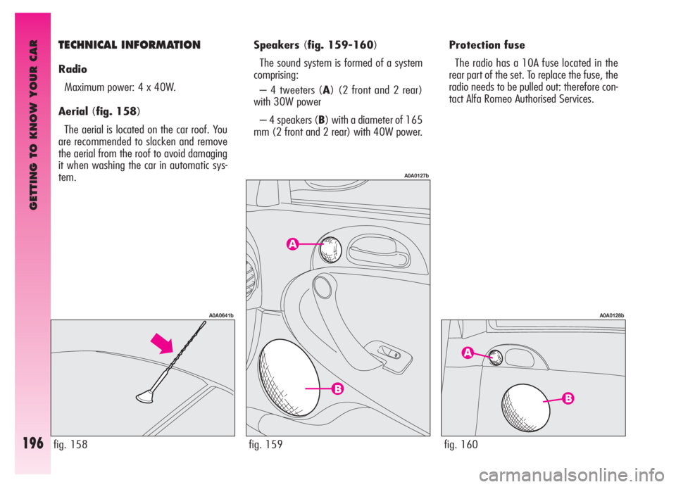
Aerial(fig. 158)
The aerial is located on the car roof. You
are recommended to slacken and remove
the aerial from the roof to avoid damaging
it when washing the car in automatic sys-
tem.
fig. 158
A0A0641b
Speakers(fig. 159-160)
The sound system is formed of a system
comprising:
– 4 tweeters (A) (2 front and 2 rear)
with 30W power
– 4 speakers (B) with a diameter of 165
mm (2 front and 2 rear) with 40W power.
Page 227 of 307

IN AN EMERGENCY
225
BULBS
High beam
Low beam
Xenon lights
Front sidelights
Foglights
Front direction indicators
Side direction indicators
Rear direction indicators
Rear sidelights - braking lights
Third stop (additional braking lights)
Reversing light
Rear foglights
Number plate light
Puddle lights
Front roof light
Rear roof light
Courtesy mirror light
Glovebox light
Boot lightFIGURE 21
D
D
F
B
E
B
A
B
B
–
B
B
A
C
C
C
A
A
CPOWER
55W
55W
35W
6W
55W
21W
5W
21W
5W/21W
–
21W
21W
5W
5W
10W
10W
1.2W
5W
5W TYPE
H7
H7
DS2
H6W
H1
PY21W
W5W
P21W
P21/5W
Led
P21W
P21W
W5W
C5W
C10W
C10W
W1.2W
W5W
C5W
Page 234 of 307

IN AN EMERGENCY
232
– disconnect the connector (C-fig. 37),
remove the led unit (D) and replace it with
a new unit;
– Refit the unit on the tailgate reversing
the above mentioned procedure.
fig. 37
A0A0632b
fig. 39
A0A0175b
PUDDLE LIGHTS (fig. 38)
(per versions/market where
provided)
To change the bulb, proceed as follows:
– Open the door and slacken the screw
(A) fastening the transparent covers.
– Remove the unit composed of the two
transparent covers then change the bulb,
releasing it from the side contacts making
sure that the new bulb is correctly
clamped between the contacts.
– Realign the two transparent covers
and tighten the fastening screw (A).
IF AN INTERIOR
LIGHT GOES OUT
FRONT ROOF LIGHT
(fig. 39-40)
To change the bulbs, proceed as follows:
– Remove the light unit (A) levering in
the points shown by the arrow (in corre-
spondence with the retainer catches).
– Open the protective cover (B).
– Replace the bulb concerned releasing
it from the side contacts making sure that
the new bulb is correctly clamped
between the contacts.
fig. 38
A0A0174b
Page 235 of 307

IN AN EMERGENCY
233
REAR ROOF LIGHT
(fig. 41-42)
To change the bulb, proceed as follows:
– Remove the light unit (A) levering in
the point shown by the arrow.
– Replace the bulb releasing it from the
side contacts making sure that the new
bulb is correctly clamped between the con-
tacts.– Refit the light unit in the correct posi-
tion inserting first the side with the con-
nector, then pressing the other side until
the catch clicks into place (B).
fig. 41
A0A0177b
fig. 42
A0A0178b
– Close the protective cover (B).
– Refit the light unit pressing gently in
correspondence with the retainer catches,
until hearing the click.
fig. 40
A0A0176b