sensor Alfa Romeo MiTo 2014 User Guide
[x] Cancel search | Manufacturer: ALFA ROMEO, Model Year: 2014, Model line: MiTo, Model: Alfa Romeo MiTo 2014Pages: 280, PDF Size: 8.79 MB
Page 70 of 280
Carry out any of the following manoeuvres to restore automatic
operation of the system:
❒movement of left stalk from the automatic position to any other
position and then back to automatic;
❒sensitivity adjustment (by turning ring nut A to increase or decrease).
When the rain sensor is reactivated using any of the manoeuvres
described above, reactivation is indicated by a single stroke of the
windscreen wipers, regardless of the condition of the windscreen.
If the sensitivity is changed whilst the rain sensor is operating, a
windscreen wiper stroke is carried out to confirm the change.
In the event of malfunction of the rain sensor whilst it is active, the
windscreen wiper operates intermittently at a speed consistent with the
sensitivity setting of the rain sensor, regardless of whether there is
rain on the glass (sensor failure is indicated on the display).
The sensor continues to operate and it is possible to set the windscreen
wiper to continuous mode (1
stor 2
ndspeed). The failure indication
remains for as long as the sensor is active.
REAR WINDOW WASHER/WIPER(for versions/markets, where provided)
Activation
This operates only with the ignition key turned to MAR.
Turn ring nut B fig. 36 from positionOto position
to operate the
rear window wiper as follows:
❒in intermittent mode when the windscreen wiper is not operating;
❒in synchronous mode (at half the speed of the windscreen wiper)
when the windscreen wiper is operating;
❒in continuous mode with reverse gear engaged and the control
active.
With reverse gear engaged and windscreen wiper on, the rear
window wiper is activated in continuous mode. Pushing the stalk
towards the dashboard (unstable position) will activate the rear
window washer jet.
Keep the stalk pushed for more than half a second to activate the rear
window wiper as well. Releasing the stalk will activate the smart
washing function, as described for the windscreen wiper.
66GETTING TO
KNOW YOUR CAR
SAFETY
STARTING AND
DRIVING
IN AN EMERGENCY
SERVICING AND
MAINTENANCE
TECHNICAL
SPECIFICATIONS
INDEX
Page 105 of 280
CAR INACTIVITYIn the event of car inactivity (or if the battery is replaced), special
attention must be paid to the disconnection of the battery power
supply.
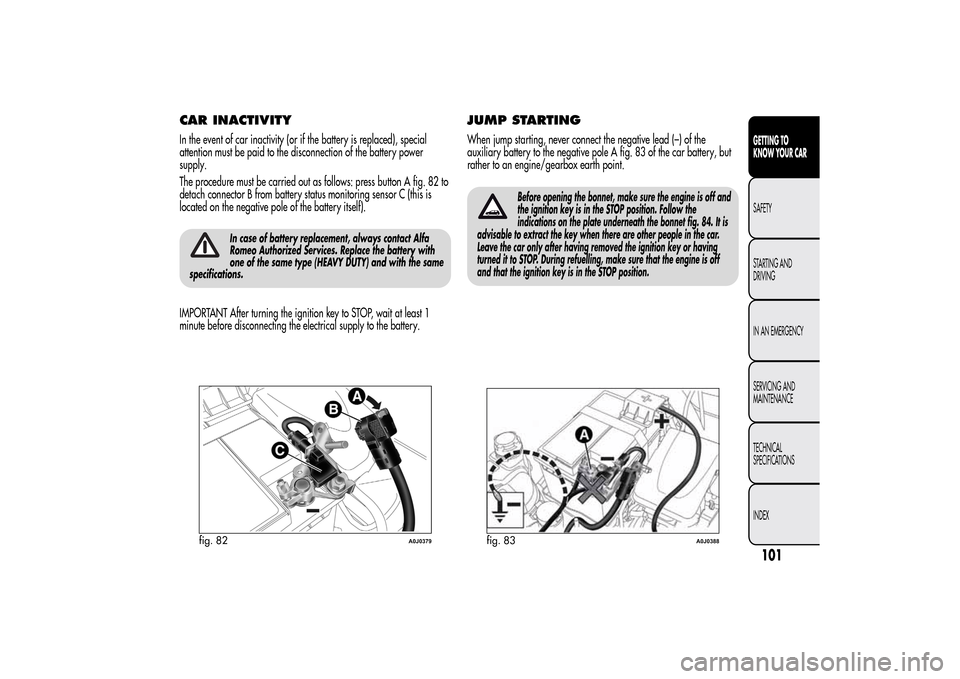
The procedure must be carried out as follows: press button A fig. 82 to
detach connector B from battery status monitoring sensor C (this is
located on the negative pole of the battery itself).
In case of battery replacement, always contact Alfa
Romeo Authorized Services. Replace the battery with
one of the same type (HEAVY DUTY) and with the same
specifications.
IMPORTANT After turning the ignition key to STOP, wait at least 1
minute before disconnecting the electrical supply to the battery.
JUMP STARTINGWhen jump starting, never connect the negative lead (–) of the
auxiliary battery to the negative pole A fig. 83 of the car battery, but
rather to an engine/gearbox earth point.
Before opening the bonnet, make sure the engine is off and
the ignition key is in the STOP position. Follow the
indications on the plate underneath the bonnet fig. 84. It is
advisable to extract the key when there are other people in the car.
Leave the car only after having removed the ignition key or having
turned it to STOP. During refuelling, make sure that the engine is off
and that the ignition key is in the STOP position.
fig. 82
A0J0379
fig. 83
A0J0388
101GETTING TO
KNOW YOUR CARSAFETY
STARTING AND
DRIVING
IN AN EMERGENCY
SERVICING AND
MAINTENANCE
TECHNICAL
SPECIFICATIONS
INDEX
Page 109 of 280

PARKING SENSORS(for versions/markets, where provided)
The parking sensors are located in the car's rear bumper fig. 86 and
their function is to inform the driver, through an intermittent acoustic
signal, about the presence of obstacles behind the car.ACTIVATIONThe sensors are activated by engaging reverse gear. As the obstacle
behind the vehicle gets closer to the car, the acoustic signal becomes
more frequent.INDICATIONS ON DISPLAY(for versions/markets, where provided)
When the sensor is activated, the "Reconfigurable multifunction
display" (for versions/markets, where provided) shows the screen
illustrated in fig. 87.
Obstacle presence and distance information is therefore provided both
by the buzzer and the instrument panel display.
If there are several obstacles the closest one is indicated.
ACOUSTIC SIGNALWhen reverse gear is engaged an acoustic signal is automatically
activated if there is an obstacle within the range of operation.
The acoustic signal:
❒increases as the distance between the car and the obstacle
decreases;
❒becomes continuous when the distance between the car and the
obstacle is less than 30 cm and stops immediately if the distance
increases;
❒remains constant if the distance remains unchanged; if this situation
concerns the side sensors, the buzzer will stop after about 3 seconds
to avoid, for example, warning indications in the event of
manoeuvres along walls.
IMPORTANT The volume of the acoustic signal can be adjusted through
the option "Warning volume" of the "Set-Up menu".
fig. 86
A0J0088
fig. 87
A0J0370
105GETTING TO
KNOW YOUR CARSAFETY
STARTING AND
DRIVING
IN AN EMERGENCY
SERVICING AND
MAINTENANCE
TECHNICAL
SPECIFICATIONS
INDEX
Page 110 of 280

Detection distances
❒Central operating range: 140 cm
❒Side operating range: 60 cm
If several obstacles are detected by the sensors, only the nearest one is
considered.OPERATION WITH TRAILERParking sensor operation is deactivated automatically when the trailer
electric cable plug is fitted into the car tow hook socket. The sensors
are automatically enabled again when the trailer's cable plug is
removed.
The sensor must be free of mud, dirt, snow or ice in order
for the system to work. Be careful not to scratch or damage
the sensors while cleaning them. Avoid using dry, rough
or hard cloths. The sensors should be washed using clean water with
the addition of car shampoo if necessary. When using special washing
equipment such as high pressure jets or steam cleaning, clean the
sensors very quickly keeping the jet more than 10 cm away.When repainting the bumpers or touching up paint in
the sensor area, contact Alfa Romeo Authorized
Services only. Incorrect paint application could affect
the operation of the parking sensors.
Parking manoeuvres however are always the driver’s
responsibility. When carrying out such manoeuvres,
always ensure that the manoeuvring area is free of
people (particularly children) and animals. The parking sensor is
designed to assist drivers, who must still never allow their
attention to lapse during potentially dangerous manoeuvres even
if performed at low speed.
GENERAL WARNINGSDuring parking manoeuvres, pay the utmost attention to any obstacles
that could be located above or below the sensors.
Objects located near the rear of the car are not detected under certain
circumstances and could therefore cause damage to the car or be
damaged.
The following conditions may influence the performance of the parking
sensor system:
❒reduced sensor sensitivity and a reduction in the parking assistance
system performance could be due to the presence on the surface of
the sensor of: ice, snow, mud, thick paint
❒the sensors may detect a non-existent obstacle (echo interference)
due to mechanical interference, for example when washing the
car, in rain (strong wind), hail;
❒The signals sent by the sensors can also be altered by the presence
of ultrasonic systems (e.g. pneumatic brake systems or pneumatic
drills) near the vehicle.
106GETTING TO
KNOW YOUR CAR
SAFETY
STARTING AND
DRIVING
IN AN EMERGENCY
SERVICING AND
MAINTENANCE
TECHNICAL
SPECIFICATIONS
INDEX
Page 111 of 280
❒sensor performance can also be influenced by the position of the
sensors. For example by a change in the ride setting (caused by
the wear of the shock absorbers, suspension), overloading the
vehicle and carrying out specific tuning operations that require the
vehicle to be lowered;
❒The detection of obstacles at the top part of the car may not be
guaranteed because the system detects obstacles that could cause an
impact with the car in the bottom part.
TPMS (Tyre Pressure
Monitoring System)(for versions/markets, where provided)
The car may be fitted with a tyre pressure monitoring system (TPMS),
which informs the driver of the tyre inflation status via the "Check
tyre pressure" and "Low tyre pressure" messages on the display.
This system comprises a radio frequency transmitter fitted to each
wheel (on the wheel rim inside the tyre), which is able to send
information on the tyre inflation pressure of each wheel to the control
unit.IMPORTANT INFORMATION ABOUT
THE TPMSThe fault indications are not stored and will therefore not be displayed
after the engine has been switched off and then on again.
If the fault conditions persist, the control unit will send the relative
indications to the instrument panel only after the car has been in
motion for a short time.
The presence of the TPMS does not permit the driver to
neglect regular checks of the tyre pressure, including
for the spare wheel.Tyre pressure must be checked with tyres rested and
cold. Should it become necessary for whatever reason
to check pressure with warm tyres, do not reduce
pressure even though it is higher than the prescribed value, but
repeat the check when tyres are cold.
107GETTING TO
KNOW YOUR CARSAFETY
STARTING AND
DRIVING
IN AN EMERGENCY
SERVICING AND
MAINTENANCE
TECHNICAL
SPECIFICATIONS
INDEX
Page 112 of 280
Should one or more wheels be fitted without sensors,
the system will no longer be available and a warning
message will be shown on the display, until 4 wheels
with sensors are fitted again.The TPMS cannot warn of sudden decreases in tyre
pressure (for example when a tyre bursts). In this case,
stop the car, braking with caution and avoiding
abrupt steering.Replacing standard tyres with winter tyres and vice
versa requires TPMS system adjustment that must only
be performed by Alfa Romeo Authorised Services.Variations in outside temperature may cause tyre
pressures to vary. The TPMS may temporarily indicate
insufficient pressure. In this case, check the tyre
pressure when cold and, if necessary, restore the inflation values.
When a tyre is removed, it is advisable to replace the
rubber valve seal as well: contact Alfa Romeo
Authorised Services. Tyre and rim fitting/removal
operations require specific precautions; to avoid damaging or
fitting the sensors incorrectly, tyre and wheel fitting/removal
operations should only be carried out by specialised staff.
Contact Alfa Romeo Authorised Services.Intense radio-frequency interference may prevent the
correct operation of the TPMS. This condition will be
indicated by a message on the display. The message
will disappear automatically as soon as the interference ceases to
affect the system.
108GETTING TO
KNOW YOUR CAR
SAFETY
STARTING AND
DRIVING
IN AN EMERGENCY
SERVICING AND
MAINTENANCE
TECHNICAL
SPECIFICATIONS
INDEX
Page 113 of 280
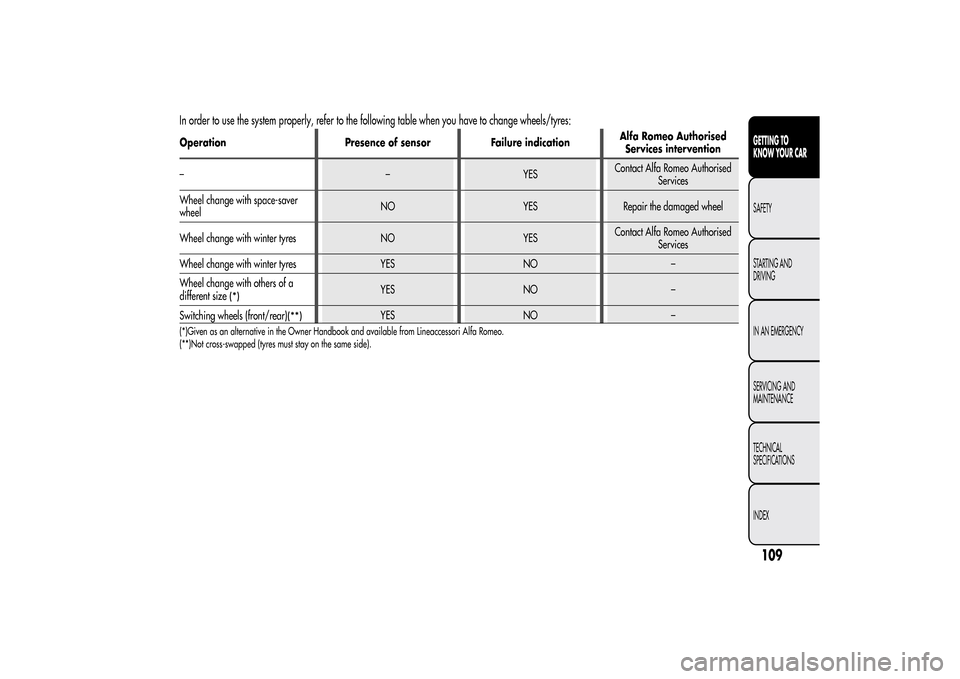
In order to use the system properly, refer to the following table when you have to change wheels/tyres:Operation Presence of sensor Failure indicationAlfa Romeo Authorised
Services intervention
– – YESContact Alfa Romeo Authorised
Services
Wheel change with space-saver
wheelNO YES Repair the damaged wheel
Wheel change with winter tyres NO YESContact Alfa Romeo Authorised
Services
Wheel change with winter tyres YES NO –
Wheel change with others of a
different size
(*)
YES NO –
Switching wheels (front/rear)
(**)
YES NO –
(*)Given as an alternative in the Owner Handbook and available from Lineaccessori Alfa Romeo.
(**)Not cross-swapped (tyres must stay on the same side).
109GETTING TO
KNOW YOUR CARSAFETY
STARTING AND
DRIVING
IN AN EMERGENCY
SERVICING AND
MAINTENANCE
TECHNICAL
SPECIFICATIONS
INDEX
Page 115 of 280
Closure
Fit the cap (complete with key) and turn it clockwise until it clicks once
or more. Then turn the key clockwise and extract it, then close the flap.
The sealing may cause a slight pressure increase in the tank. A little
breathing off, while slackening the cap is absolutely normal.
Do not place naked flames or lit cigarettes near to the
fuel filler: fire risk. Also, keep your face away from
this fuel inlet to avoid inhaling harmful fumes.
PROTECTING THE ENVIRONMENTThe following devices are used for reducing petrol fuel engine
emissions: catalytic converter, oxygen sensors and evaporation control
system
The following devices are used for reducing diesel fuel engine
emissions: oxidising catalytic converter, exhaust gas recirculation
system (EGR) and particulate filter (DPF).DIESEL PARTICULATE FILTER (DPF)(Diesel Particulate Filter)
(for versions/markets, where provided)
The Diesel Particulate Filter is a mechanical filter, integral to the
exhaust system, that physically traps carbon particles present in the
exhaust gases of diesel engines.
The diesel particulate filter is needed to eliminate almost all carbon
particle emissions in compliance with current/future regulations and
standards.
During standard use of the vehicle, the engine control unit records a set
of data (e.g.: travel time, type of route, temperatures, etc.) and it will
then calculate how much particulate has been trapped by the filter.
Since this filter physically traps particulate, it should be periodically
regenerated (cleaned) at regular intervals by burning carbon particles.
111GETTING TO
KNOW YOUR CARSAFETY
STARTING AND
DRIVING
IN AN EMERGENCY
SERVICING AND
MAINTENANCE
TECHNICAL
SPECIFICATIONS
INDEX
Page 172 of 280
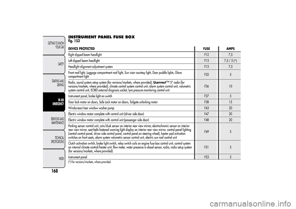
INSTRUMENT PANEL FUSE BOXfig. 153DEVICE PROTECTEDFUSE AMPS
Right dipped beam headlightF12 7,5
Left dipped beam headlightF13
7,5/5
(*)
Headlight alignment adjustment systemF13 7,5
Front roof light, Luggage compartment roof light, Sun visor courtesy light, Door puddle lights, Glove
compartment lightF32 5
Radio, sound system setup system (for versions/markets, where provided),Uconnect
™
5" radio (for
versions/markets, where provided), climate control system control unit, alarm system control unit, volumetric
system control unit, EOBD external diagnosis socket, tyre pressure monitoring control unitF36 10
Instrument panel, brake light on switchF37 5
Door lock motor on doors, Safe Lock motor on doors, Tailgate unlocking motor F38 15
Windscreen/rear window washer pumpF43 20
Electric window motor complete with control unit (driver side door) F47 20
Electric window motor complete with control unit (passenger side door) F48 20
Parking sensor control unit, rain/dusk sensor on interior rear view mirror, electrochromic sensor on interior
rear view mirror, seat belts fastened warning light display on interior rear view mirror, control panel lighting
(central control panel, driver side control panel, control panel on steering wheel), heater pad activation
switches on front seats, alarm system volumetric sensor control unit, electric sun roof control unitF49 5
Clutch activation switch, brake light switch, relay switch coils on engine fuse box control unit, control system
on internal climate control/heater unit, flow meter, water presence in diesel sensor, radio, radio setup system
(for versions/markets, where provided)F51 5
Instrument panelF53 5
(*) For versions/markets, where provided
168GETTING TO KNOW
YOUR CAR
SAFETY
STARTING AND
DRIVING
IN AN
EMERGENCY
SERVICING AND
MAINTENANCE
TECHNICAL
SPECIFICATIONS
INDEX
Page 174 of 280
BATTERY RECHARGINGIMPORTANT The battery recharging procedure is given as information
only. Contact Alfa Romeo Authorized Services to carry out this
operation.
IMPORTANT After turning the ignition key to STOP, wait at least 1
minute before disconnecting the battery power supply.
We recommend recharging the battery slowly for approximately 24
hours at low amperage. Charging for a longer time may damage the
battery.VERSIONS WITHOUT Start&Stop
SYSTEM(for versions/markets, where provided)
Charge the battery as follows:
❒disconnect the negative battery terminal;
❒connect the charger cables to the battery terminals, observing the
polarity;
❒turn on the battery charger;
❒when it is recharged, turn the charger off before disconnecting it
from the battery;
❒reconnect the negative battery terminal.
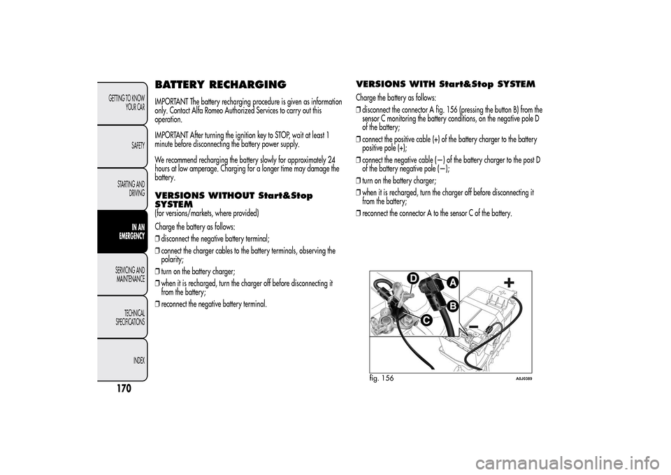
VERSIONS WITH Start&Stop SYSTEMCharge the battery as follows:
❒disconnect the connector A fig. 156 (pressing the button B) from the
sensor C monitoring the battery conditions, on the negative pole D
of the battery;
❒connect the positive cable (+) of the battery charger to the battery
positive pole (+);
❒connect the negative cable (—) of the battery charger to the post D
of the battery negative pole (—);
❒turn on the battery charger;
❒when it is recharged, turn the charger off before disconnecting it
from the battery;
❒reconnect the connector A to the sensor C of the battery.
fig. 156
A0J0389
170GETTING TO KNOW
YOUR CAR
SAFETY
STARTING AND
DRIVING
IN AN
EMERGENCY
SERVICING AND
MAINTENANCE
TECHNICAL
SPECIFICATIONS
INDEX