technical specifications Alfa Romeo MiTo 2014 Service Manual
[x] Cancel search | Manufacturer: ALFA ROMEO, Model Year: 2014, Model line: MiTo, Model: Alfa Romeo MiTo 2014Pages: 280, PDF Size: 8.79 MB
Page 46 of 280
SWITCHING OFF THE ALARMPress the
button. The following operations are performed (excluding
specific markets):
❒the direction indicators flash briefly twice;
❒there are two brief acoustic signals;
❒unlocking of the doors.
IMPORTANT The alarm does not switch off when the central opening is
activated using the metal insert in the key.
VOLUMETRIC/ANTI-LIFT PROTECTIONTo guarantee the correct operation of the protection, close the side
windows and any sun roof completely (for versions/markets, where
provided).
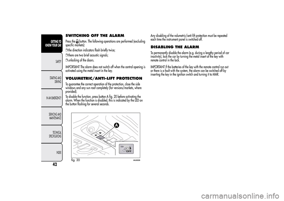
To disable the function, press button A fig. 20 before activating the
alarm. When the function is disabled, this is indicated by the LED on
the button flashing for several seconds.Any disabling of the volumetric/anti-lift protection must be repeated
each time the instrument panel is switched off.
DISABLING THE ALARMTo permanently disable the alarm (e.g. during a lengthy period of car
inactivity), lock the car by turning the metal insert of the key with
remote control in the lock.
IMPORTANT If the batteries of the key with the remote control run out
or there is a fault with the system, the alarm can be switched off by
inserting the key in the ignition switch and turning it to MAR.
fig. 20
A0J0226
42GETTING TO
KNOW YOUR CAR
SAFETY
STARTING AND
DRIVING
IN AN EMERGENCY
SERVICING AND
MAINTENANCE
TECHNICAL
SPECIFICATIONS
INDEX
Page 47 of 280
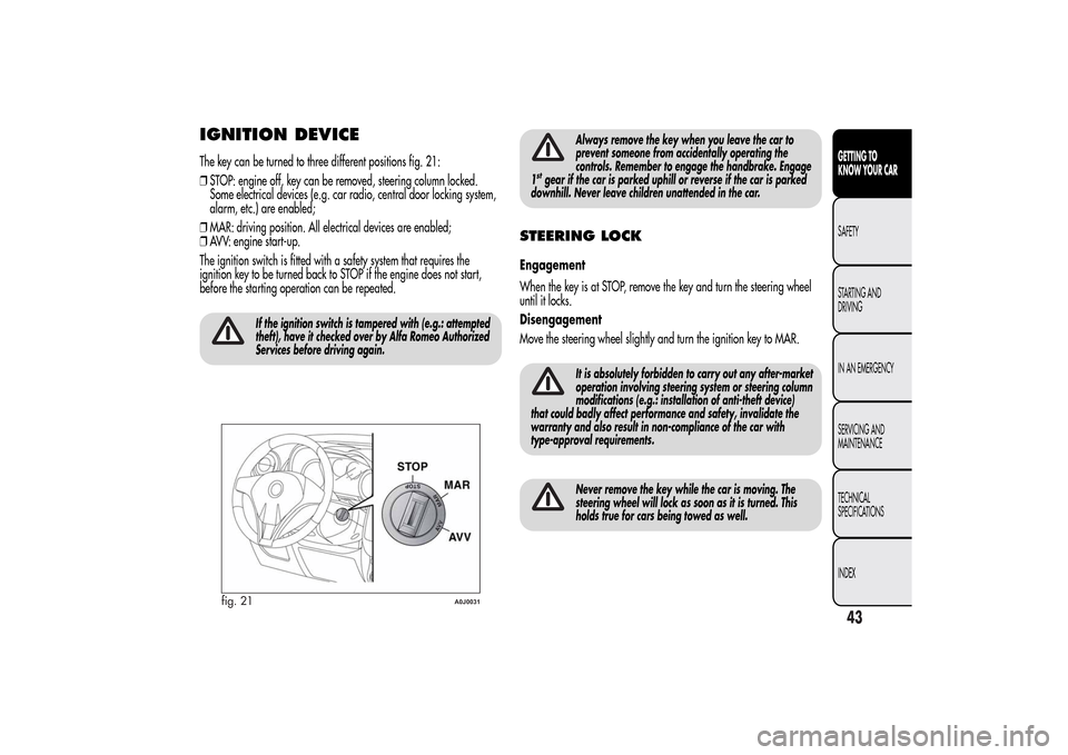
IGNITION DEVICEThe key can be turned to three different positions fig. 21:
❒STOP: engine off, key can be removed, steering column locked.
Some electrical devices (e.g. car radio, central door locking system,
alarm, etc.) are enabled;
❒MAR: driving position. All electrical devices are enabled;
❒AVV: engine start-up.
The ignition switch is fitted with a safety system that requires the
ignition key to be turned back to STOP if the engine does not start,
before the starting operation can be repeated.
If the ignition switch is tampered with (e.g.: attempted
theft), have it checked over by Alfa Romeo Authorized
Services before driving again.
Always remove the key when you leave the car to
prevent someone from accidentally operating the
controls. Remember to engage the handbrake. Engage
1
stgear if the car is parked uphill or reverse if the car is parked
downhill. Never leave children unattended in the car.
STEERING LOCKEngagement
When the key is at STOP, remove the key and turn the steering wheel
until it locks.
Disengagement
Move the steering wheel slightly and turn the ignition key to MAR.
It is absolutely forbidden to carry out any after-market
operation involving steering system or steering column
modifications (e.g.: installation of anti-theft device)
that could badly affect performance and safety, invalidate the
warranty and also result in non-compliance of the car with
type-approval requirements.Never remove the key while the car is moving. The
steering wheel will lock as soon as it is turned. This
holds true for cars being towed as well.
fig. 21
A0J0031
43GETTING TO
KNOW YOUR CARSAFETY
STARTING AND
DRIVING
IN AN EMERGENCY
SERVICING AND
MAINTENANCE
TECHNICAL
SPECIFICATIONS
INDEX
Page 48 of 280
SEATSFRONT SEATS
All adjustments must be made with the car stationary.
Lengthwise adjustment
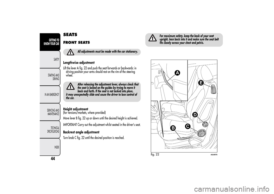
Lift the lever A fig. 22 and push the seat forwards or backwards: in
driving position your arms should rest on the rim of the steering
wheel.
After releasing the adjustment lever, always check that
the seat is locked on the guides by trying to move it
back and forth. If the seat is not locked into place,
it may unexpectedly slide and cause the driver to lose control of
the car.
Height adjustment
(for versions/markets, where provided)
Move lever B fig. 22 up or down until the desired height is achieved.
IMPORTANT Carry out the adjustment whilst seated in the driver's seat.
Backrest angle adjustment
Turn knob C fig. 22 until the desired position is reached.
For maximum safety, keep the back of your seat
upright, lean back into it and make sure the seat belt
fits closely across your chest and pelvis.
fig. 22
A0J0078
44GETTING TO
KNOW YOUR CAR
SAFETY
STARTING AND
DRIVING
IN AN EMERGENCY
SERVICING AND
MAINTENANCE
TECHNICAL
SPECIFICATIONS
INDEX
Page 49 of 280
Lumbar adjustment
(for versions/markets, where provided)
Turn knob D fig. 22 until the desired position is reached.
Backrest folding
To access the rear seats, pull handle E upwards fig. 22: the backrest
will fold and the seat will slide forwards when you push the backrest.
Moving the backrest backwards will return the seat to its initial
position.
Always check that the seat is firmly locked on the
guides, trying to push it forwards and backwards.
Seat heating
(for versions/markets, where provided)
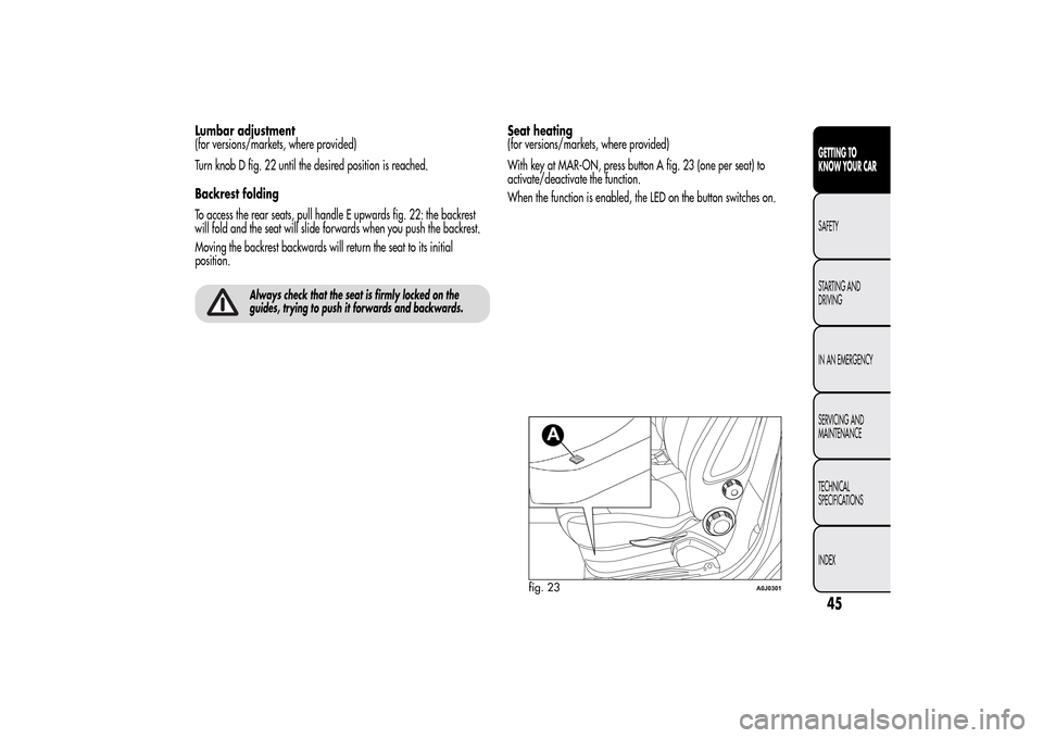
With key at MAR-ON, press button A fig. 23 (one per seat) to
activate/deactivate the function.
When the function is enabled, the LED on the button switches on.
fig. 23
A0J0301
45GETTING TO
KNOW YOUR CARSAFETY
STARTING AND
DRIVING
IN AN EMERGENCY
SERVICING AND
MAINTENANCE
TECHNICAL
SPECIFICATIONS
INDEX
Page 50 of 280
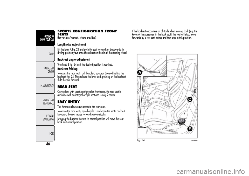
SPORTS CONFIGURATION FRONT
SEATS(for versions/markets, where provided)
Lengthwise adjustment
Lift the lever A fig. 24 and push the seat forwards or backwards: in
driving position your arms should rest on the rim of the steering wheel.
Backrest angle adjustment
Turn knob B fig. 24 until the desired position is reached.
Backrest folding
To access the rear seats, pull handle C upwards (located behind the
backrest) fig. 24. Then release the lever and, pushing on the backrest,
slide the seat forward.REAR SEATOn versions with sports configuration front seats, the rear seat is
available with an integral or split seat and is only 2-seater.EASY ENTRYThis function allows easy access to the rear seats.
To access the rear seats, raise handle E and move the seat’s backrest
forwards: the seat moves forwards automatically.
Bringing the backrest back to its normal position will move the seat
back to its initial position.If the backrest encounters an obstacle when moving back (e.g. the
knees of the passenger in the back seat), the seat will stop, move
forwards by a few centimetres and then stop in this position.
fig. 24
A0J0163
46GETTING TO
KNOW YOUR CAR
SAFETY
STARTING AND
DRIVING
IN AN EMERGENCY
SERVICING AND
MAINTENANCE
TECHNICAL
SPECIFICATIONS
INDEX
Page 51 of 280
HEAD RESTRAINTSFRONTHead restraints are adjustable in height and they lock automatically
into the desired position:
❒upwards adjustment: raise the head restraint until it clicks into place;
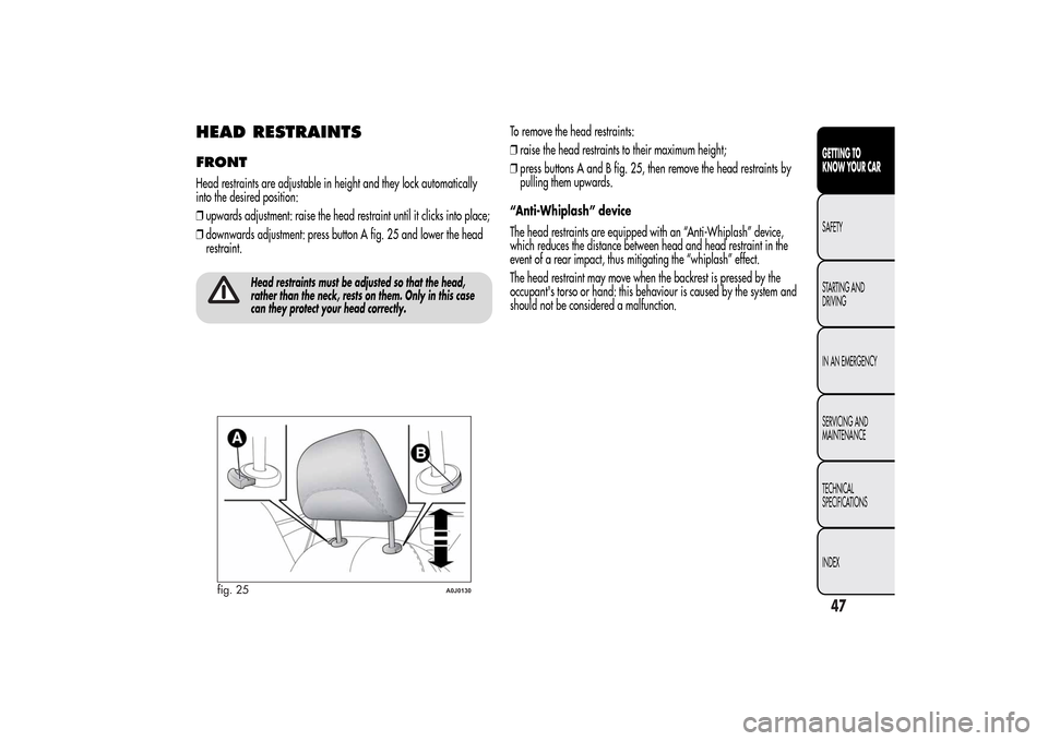
❒downwards adjustment: press button A fig. 25 and lower the head
restraint.
Head restraints must be adjusted so that the head,
rather than the neck, rests on them. Only in this case
can they protect your head correctly.
To remove the head restraints:
❒raise the head restraints to their maximum height;
❒press buttons A and B fig. 25, then remove the head restraints by
pulling them upwards.
“Anti-Whiplash” device
The head restraints are equipped with an “Anti-Whiplash” device,
which reduces the distance between head and head restraint in the
event of a rear impact, thus mitigating the “whiplash” effect.
The head restraint may move when the backrest is pressed by the
occupant's torso or hand: this behaviour is caused by the system and
should not be considered a malfunction.
fig. 25
A0J0130
47GETTING TO
KNOW YOUR CARSAFETY
STARTING AND
DRIVING
IN AN EMERGENCY
SERVICING AND
MAINTENANCE
TECHNICAL
SPECIFICATIONS
INDEX
Page 52 of 280
REARTwo height-adjustable head restraints are provided for the back seats
(to adjust the height see the previous paragraph).
On some versions a head restraint is also provided for the central seat.
To remove the head restraints:
❒raise the head restraints to their maximum height;
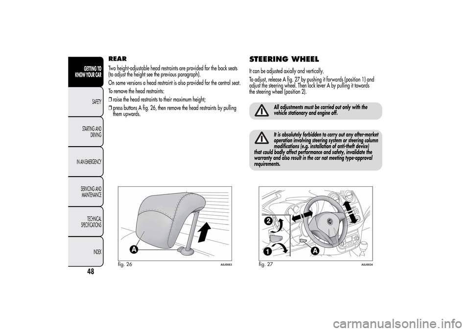
❒press buttons A fig. 26, then remove the head restraints by pulling
them upwards.
STEERING WHEELIt can be adjusted axially and vertically.
To adjust, release A fig. 27 by pushing it forwards (position 1) and
adjust the steering wheel. Then lock lever A by pulling it towards
the steering wheel (position 2).
All adjustments must be carried out only with the
vehicle stationary and engine off.It is absolutely forbidden to carry out any after-market
operation involving steering system or steering column
modifications (e.g. installation of anti-theft device)
that could badly affect performance and safety, invalidate the
warranty and also result in the car not meeting type-approval
requirements.
fig. 26
A0J0083
fig. 27
A0J0034
48GETTING TO
KNOW YOUR CAR
SAFETY
STARTING AND
DRIVING
IN AN EMERGENCY
SERVICING AND
MAINTENANCE
TECHNICAL
SPECIFICATIONS
INDEX
Page 53 of 280
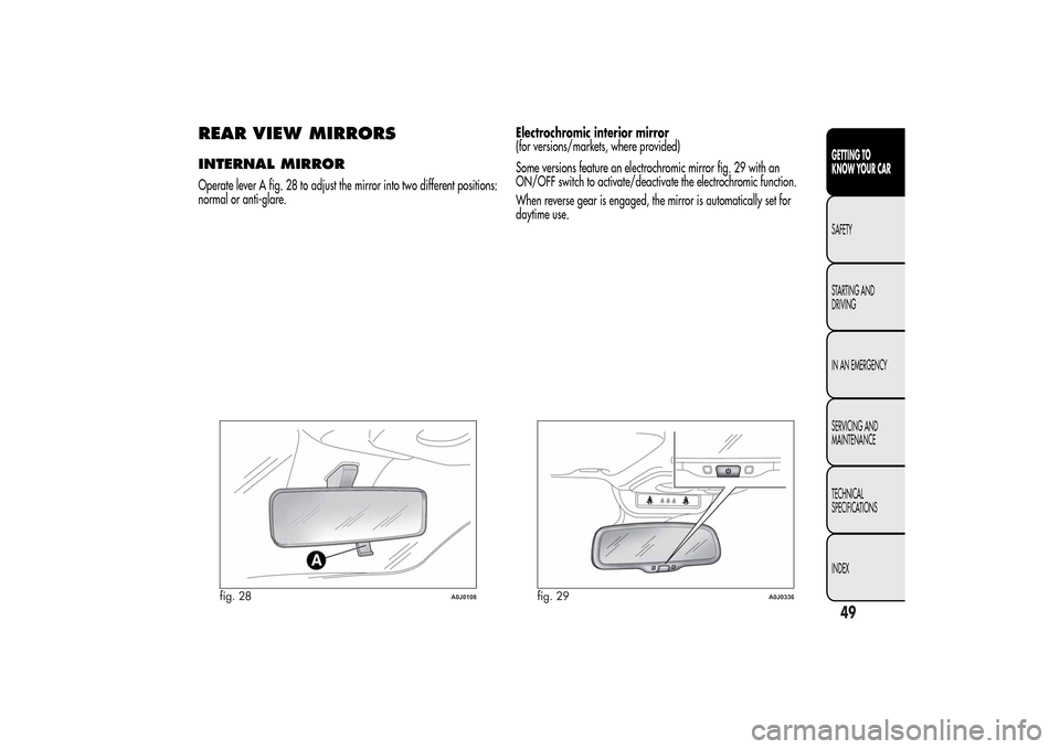
REAR VIEW MIRRORSINTERNAL MIRROROperate lever A fig. 28 to adjust the mirror into two different positions:
normal or anti-glare.Electrochromic interior mirror
(for versions/markets, where provided)
Some versions feature an electrochromic mirror fig. 29 with an
ON/OFF switch to activate/deactivate the electrochromic function.
When reverse gear is engaged, the mirror is automatically set for
daytime use.
fig. 28
A0J0108
fig. 29
A0J0336
49GETTING TO
KNOW YOUR CARSAFETY
STARTING AND
DRIVING
IN AN EMERGENCY
SERVICING AND
MAINTENANCE
TECHNICAL
SPECIFICATIONS
INDEX
Page 54 of 280
DOOR MIRRORS
As the driver's door mirror is curved, it may slightly
alter the perception of distance.
Mirror adjustment
The mirrors can only be adjusted/folded with the ignition in the MAR
position.
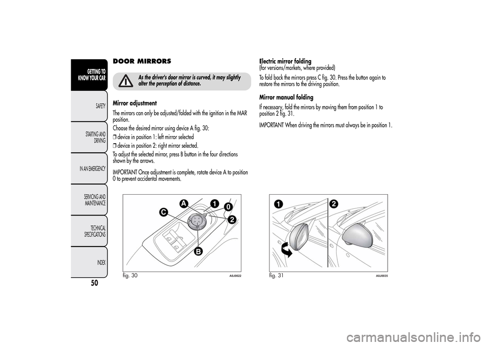
Choose the desired mirror using device A fig. 30:
❒device in position 1: left mirror selected
❒device in position 2: right mirror selected.
To adjust the selected mirror, press B button in the four directions
shown by the arrows.
IMPORTANT Once adjustment is complete, rotate device A to position
0 to prevent accidental movements.Electric mirror folding
(for versions/markets, where provided)
To fold back the mirrors press C fig. 30. Press the button again to
restore the mirrors to the driving position.
Mirror manual folding
If necessary, fold the mirrors by moving them from position 1 to
position 2 fig. 31.
IMPORTANT When driving the mirrors must always be in position 1.
fig. 30
A0J0022
fig. 31
A0J0035
50GETTING TO
KNOW YOUR CAR
SAFETY
STARTING AND
DRIVING
IN AN EMERGENCY
SERVICING AND
MAINTENANCE
TECHNICAL
SPECIFICATIONS
INDEX
Page 55 of 280
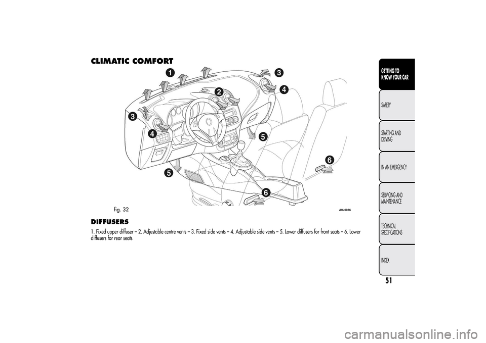
CLIMATIC COMFORTDIFFUSERS1. Fixed upper diffuser – 2. Adjustable centre vents – 3. Fixed side vents – 4. Adjustable side vents – 5. Lower diffusers for front seats – 6. Lower
diffusers for rear seats
fig. 32
A0J0036
51GETTING TO
KNOW YOUR CARSAFETY
STARTING AND
DRIVING
IN AN EMERGENCY
SERVICING AND
MAINTENANCE
TECHNICAL
SPECIFICATIONS
INDEX