fog light Alfa Romeo MiTo 2016 Owner's Manual
[x] Cancel search | Manufacturer: ALFA ROMEO, Model Year: 2016, Model line: MiTo, Model: Alfa Romeo MiTo 2016Pages: 280, PDF Size: 8.52 MB
Page 19 of 280
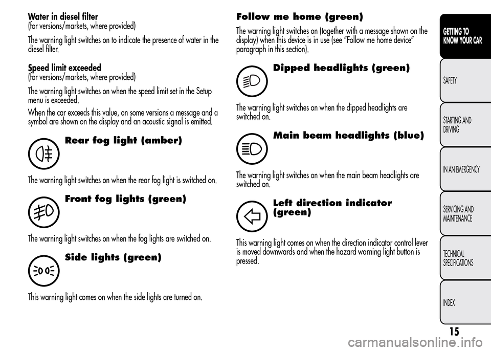
Water in diesel filter
(for versions/markets, where provided)
The warning light switches on to indicate the presence of water in the
diesel filter.
Speed limit exceeded
(for versions/markets, where provided)
The warning light switches on when the speed limit set in the Setup
menu is exceeded.
When the car exceeds this value, on some versions a message and a
symbol are shown on the display and an acoustic signal is emitted.
Rear fog light (amber)
The warning light switches on when the rear fog light is switched on.
Front fog lights (green)
The warning light switches on when the fog lights are switched on.
Side lights (green)
This warning light comes on when the side lights are turned on.
Follow me home (green)
The warning light switches on (together with a message shown on the
display) when this device is in use (see “Follow me home device”
paragraph in this section).
2
Dipped headlights (green)
The warning light switches on when the dipped headlights are
switched on.
Main beam headlights (blue)
The warning light switches on when the main beam headlights are
switched on.
Left direction indicator
(green)
This warning light comes on when the direction indicator control lever
is moved downwards and when the hazard warning light button is
pressed.
15
GETTING TO
KNOW YOUR CAR
SAFETY
STARTING AND
DRIVING
IN AN EMERGENCY
SERVICING AND
MAINTENANCE
TECHNICAL
SPECIFICATIONS
INDEX
Page 21 of 280
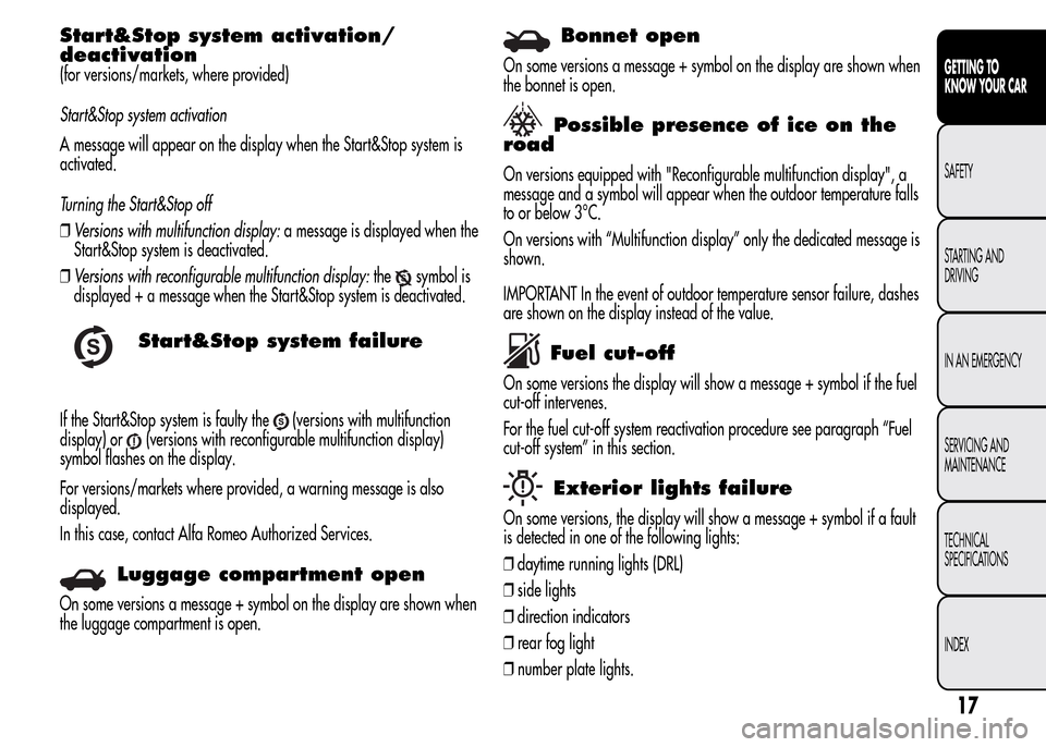
Start&Stop system activation/
deactivation
(for versions/markets, where provided)
Start&Stop system activation
A message will appear on the display when the Start&Stop system is
activated.
Turning the Start&Stop off
❒Versions with multifunction display:a message is displayed when the
Start&Stop system is deactivated.
❒Versions with reconfigurable multifunction display:the
symbol is
displayed + a message when the Start&Stop system is deactivated.
Start&Stop system failure
If the Start&Stop system is faulty the(versions with multifunction
display) or
(versions with reconfigurable multifunction display)
symbol flashes on the display.
For versions/markets where provided, a warning message is also
displayed.
In this case, contact Alfa Romeo Authorized Services.
Luggage compartment open
On some versions a message + symbol on the display are shown when
the luggage compartment is open.
Bonnet open
On some versions a message + symbol on the display are shown when
the bonnet is open.
Possible presence of ice on the
road
On versions equipped with "Reconfigurable multifunction display", a
message and a symbol will appear when the outdoor temperature falls
to or below 3°C.
On versions with “Multifunction display” only the dedicated message is
shown.
IMPORTANT In the event of outdoor temperature sensor failure, dashes
are shown on the display instead of the value.
Fuel cut-off
On some versions the display will show a message + symbol if the fuel
cut-off intervenes.
For the fuel cut-off system reactivation procedure see paragraph “Fuel
cut-off system” in this section.
Exterior lights failure
On some versions, the display will show a message + symbol if a fault
is detected in one of the following lights:
❒daytime running lights (DRL)
❒side lights
❒direction indicators
❒rear fog light
❒number plate lights.
17
GETTING TO
KNOW YOUR CAR
SAFETY
STARTING AND
DRIVING
IN AN EMERGENCY
SERVICING AND
MAINTENANCE
TECHNICAL
SPECIFICATIONS
INDEX
Page 64 of 280
SIDE LIGHTS/DIPPED BEAM
HEADLIGHTS
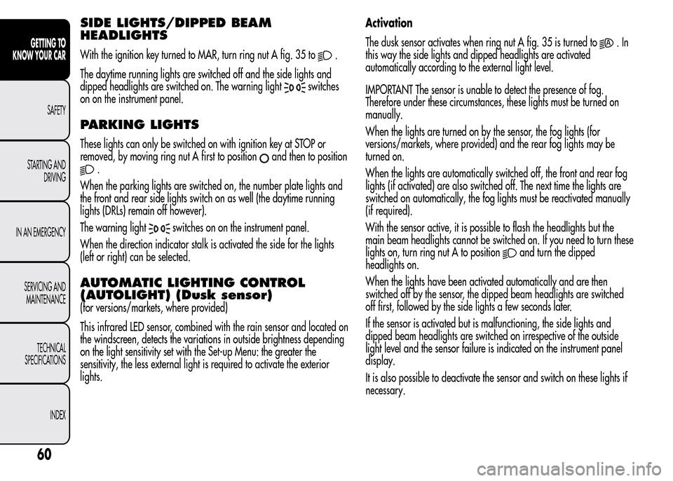
With the ignition key turned to MAR, turn ring nut A fig. 35 to.
The daytime running lights are switched off and the side lights and
dipped headlights are switched on. The warning light
switches
on on the instrument panel.
PARKING LIGHTS
These lights can only be switched on with ignition key at STOP or
removed, by moving ring nut A first to position
and then to position
.
When the parking lights are switched on, the number plate lights and
the front and rear side lights switch on as well (the daytime running
lights (DRLs) remain off however).
The warning light
switches on on the instrument panel.
When the direction indicator stalk is activated the side for the lights
(left or right) can be selected.
AUTOMATIC LIGHTING CONTROL
(AUTOLIGHT) (Dusk sensor)
(for versions/markets, where provided)
This infrared LED sensor, combined with the rain sensor and located on
the windscreen, detects the variations in outside brightness depending
on the light sensitivity set with the Set-up Menu: the greater the
sensitivity, the less external light is required to activate the exterior
lights.Activation
The dusk sensor activates when ring nut A fig. 35 is turned to
.In
this way the side lights and dipped headlights are activated
automatically according to the external light level.
IMPORTANT The sensor is unable to detect the presence of fog.
Therefore under these circumstances, these lights must be turned on
manually.
When the lights are turned on by the sensor, the fog lights (for
versions/markets, where provided) and the rear fog lights may be
turned on.
When the lights are automatically switched off, the front and rear fog
lights (if activated) are also switched off. The next time the lights are
switched on automatically, the fog lights must be reactivated manually
(if required).
With the sensor active, it is possible to flash the headlights but the
main beam headlights cannot be switched on. If you need to turn these
lights on, turn ring nut A to position
and turn the dipped
headlights on.
When the lights have been activated automatically and are then
switched off by the sensor, the dipped beam headlights are switched
off first, followed by the side lights a few seconds later.
If the sensor is activated but is malfunctioning, the side lights and
dipped beam headlights are switched on irrespective of the outside
light level and the sensor failure is indicated on the instrument panel
display.
It is also possible to deactivate the sensor and switch on these lights if
necessary.
60
GETTING TO
KNOW YOUR CAR
SAFETY
STARTING AND
DRIVING
IN AN EMERGENCY
SERVICING AND
MAINTENANCE
TECHNICAL
SPECIFICATIONS
INDEX
Page 74 of 280
FOG LIGHTS
(for versions/markets, where provided)
Operation
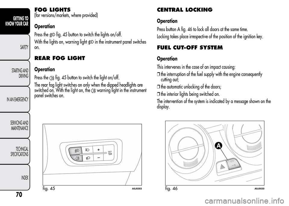
Press the
fig. 45 button to switch the lights on/off.
With the lights on, warning light
in the instrument panel switches
on.
REAR FOG LIGHT
Operation
Press the
fig. 45 button to switch the light on/off.
The rear fog light switches on only when the dipped headlights are
switched on. With the light on, the
warning light in the instrument
panel switches on.
CENTRAL LOCKING
Operation
Press button A fig. 46 to lock all doors at the same time.
Locking takes place irrespective of the position of the ignition key.
FUEL CUT-OFF SYSTEM
Operation
This intervenes in the case of an impact causing:
❒the interruption of the fuel supply with the engine consequently
cutting out;
❒the automatic unlocking of the doors;
❒the interior lights being switched on.
The intervention of the system is indicated by a message shown on the
display.
fig. 45A0J0303fig. 46A0J0030
70
GETTING TO
KNOW YOUR CAR
SAFETY
STARTING AND
DRIVING
IN AN EMERGENCY
SERVICING AND
MAINTENANCE
TECHNICAL
SPECIFICATIONS
INDEX
Page 91 of 280
HEADLIGHTS
LIGHT BEAM DIRECTION
The correct orientation of the headlights is important for the driver's
comfort and safety as well as for all other road users. This is also
covered by a specific rule of the highway code.
The headlights must be correctly aligned to ensure the best visibility
conditions for yourself and others when driving with lights on. To check
and, if necessary, adjust, contact Alfa Romeo Authorized Services.
HEADLIGHT ALIGNMENT CORRECTOR
This device works with the ignition key in the MAR position and the
dipped headlights on.
Headlight alignment adjustment
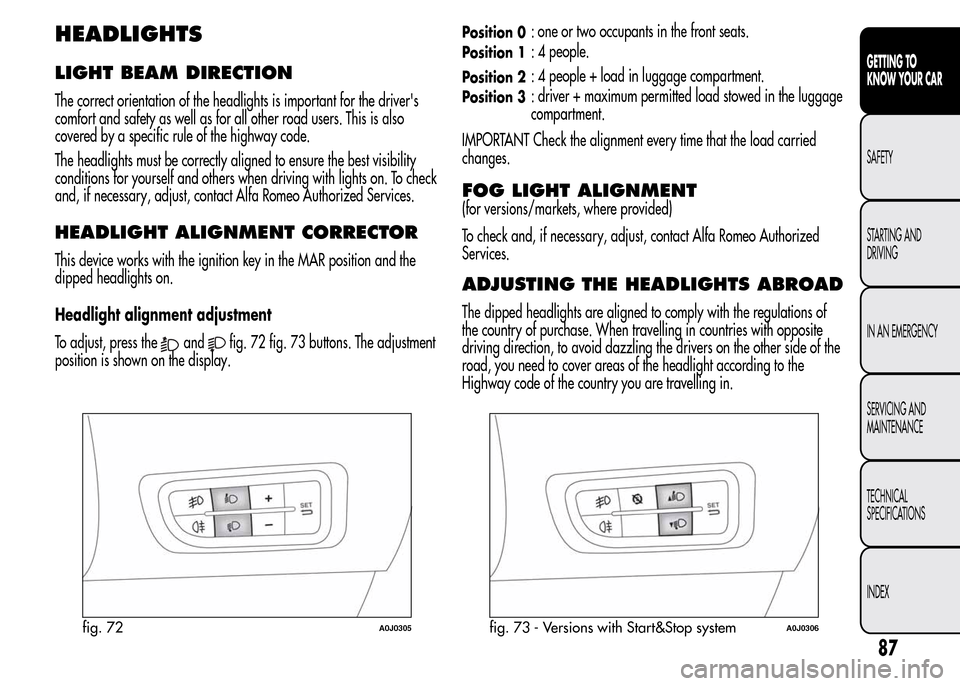
To adjust, press the
andfig. 72 fig. 73 buttons. The adjustment
position is shown on the display.
Position 0: one or two occupants in the front seats.
Position 1: 4 people.
Position 2: 4 people + load in luggage compartment.
Position 3: driver + maximum permitted load stowed in the luggage
compartment.
IMPORTANT Check the alignment every time that the load carried
changes.
FOG LIGHT ALIGNMENT
(for versions/markets, where provided)
To check and, if necessary, adjust, contact Alfa Romeo Authorized
Services.
ADJUSTING THE HEADLIGHTS ABROAD
The dipped headlights are aligned to comply with the regulations of
the country of purchase. When travelling in countries with opposite
driving direction, to avoid dazzling the drivers on the other side of the
road, you need to cover areas of the headlight according to the
Highway code of the country you are travelling in.
fig. 72A0J0305fig. 73 - Versions with Start&Stop systemA0J0306
87
GETTING TO
KNOW YOUR CAR
SAFETY
STARTING AND
DRIVING
IN AN EMERGENCY
SERVICING AND
MAINTENANCE
TECHNICAL
SPECIFICATIONS
INDEX
Page 138 of 280
On models with 6 gears, to engage 6thgear, press the lever slightly to
the right to avoid changing into 4thby mistake. The same applies to the
shift from 6thto 5thgear.
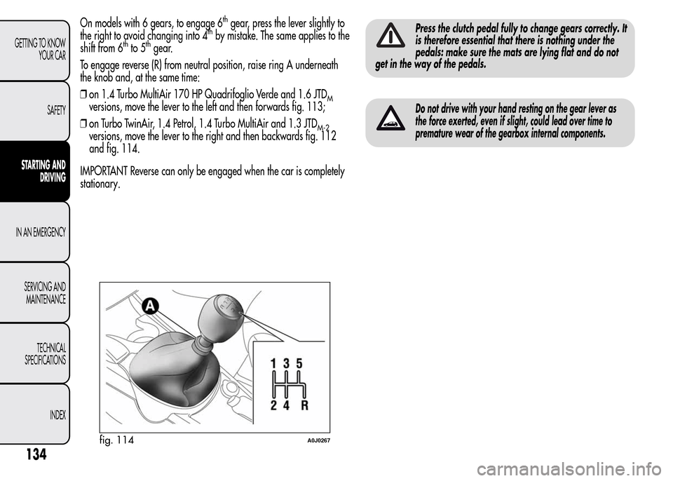
To engage reverse (R) from neutral position, raise ring A underneath
the knob and, at the same time:
❒on 1.4 Turbo MultiAir 170 HP Quadrifoglio Verde and 1.6 JTD
Mversions, move the lever to the left and then forwards fig. 113;
❒on Turbo TwinAir, 1.4 Petrol, 1.4 Turbo MultiAir and 1.3 JTD
M-2versions, move the lever to the right and then backwards fig. 112
and fig. 114.
IMPORTANT Reverse can only be engaged when the car is completely
stationary.
Press the clutch pedal fully to change gears correctly. It
is therefore essential that there is nothing under the
pedals: make sure the mats are lying flat and do not
get in the way of the pedals.
Do not drive with your hand resting on the gear lever as
the force exerted, even if slight, could lead over time to
premature wear of the gearbox internal components.
fig. 114A0J0267
134
GETTING TO KNOW
YOUR CAR
SAFETY
STARTING AND
DRIVING
IN AN EMERGENCY
SERVICING AND
MAINTENANCE
TECHNICAL
SPECIFICATIONS
INDEX
Page 157 of 280
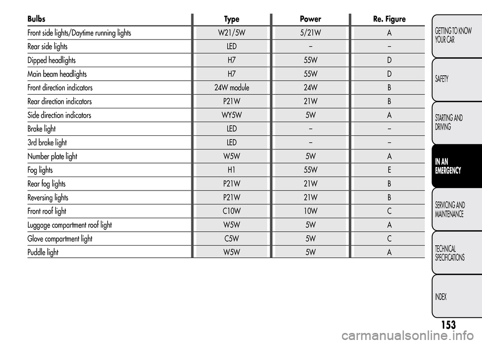
Bulbs Type Power Re. Figure
Front side lights/Daytime running lights W21/5W 5/21W A
Rear side lights LED – –
Dipped headlights H7 55W D
Main beam headlights H7 55W D
Front direction indicators 24W module 24W B
Rear direction indicators P21W 21W B
Side direction indicators WY5W 5W A
Brake light LED – –
3rd brake light LED – –
Number plate light W5W 5W A
Fog lights H1 55W E
Rear fog lights P21W 21W B
Reversing lights P21W 21W B
Front roof light C10W 10W C
Luggage compartment roof light W5W 5W A
Glove compartment light C5W 5W C
Puddle light W5W 5W A
153
GETTING TO KNOW
YOUR CAR
SAFETY
STARTING AND
DRIVING
IN AN
EMERGENCY
SERVICING AND
MAINTENANCE
TECHNICAL
SPECIFICATIONS
INDEX
Page 160 of 280
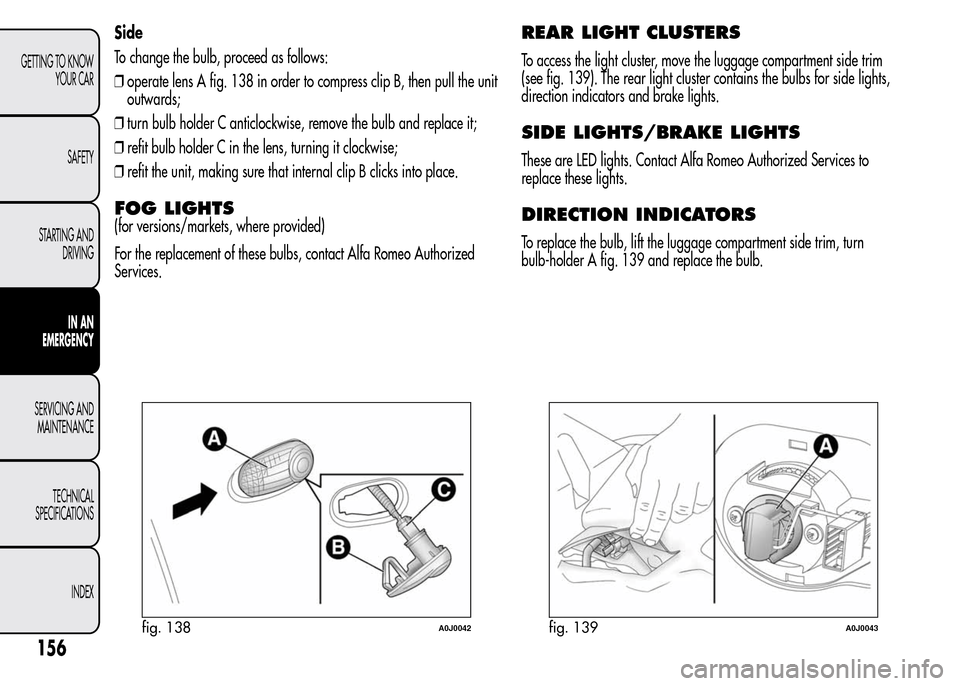
Side
To change the bulb, proceed as follows:
❒operate lens A fig. 138 in order to compress clip B, then pull the unit
outwards;
❒turn bulb holder C anticlockwise, remove the bulb and replace it;
❒refit bulb holder C in the lens, turning it clockwise;
❒refit the unit, making sure that internal clip B clicks into place.
FOG LIGHTS
(for versions/markets, where provided)
For the replacement of these bulbs, contact Alfa Romeo Authorized
Services.
REAR LIGHT CLUSTERS
To access the light cluster, move the luggage compartment side trim
(see fig. 139). The rear light cluster contains the bulbs for side lights,
direction indicators and brake lights.
SIDE LIGHTS/BRAKE LIGHTS
These are LED lights. Contact Alfa Romeo Authorized Services to
replace these lights.
DIRECTION INDICATORS
To replace the bulb, lift the luggage compartment side trim, turn
bulb-holder A fig. 139 and replace the bulb.
fig. 138A0J0042fig. 139A0J0043
156
GETTING TO KNOW
YOUR CAR
SAFETY
STARTING AND
DRIVING
IN AN
EMERGENCY
SERVICING AND
MAINTENANCE
TECHNICAL
SPECIFICATIONS
INDEX
Page 161 of 280
REAR FOG LIGHT/REVERSING LIGHT
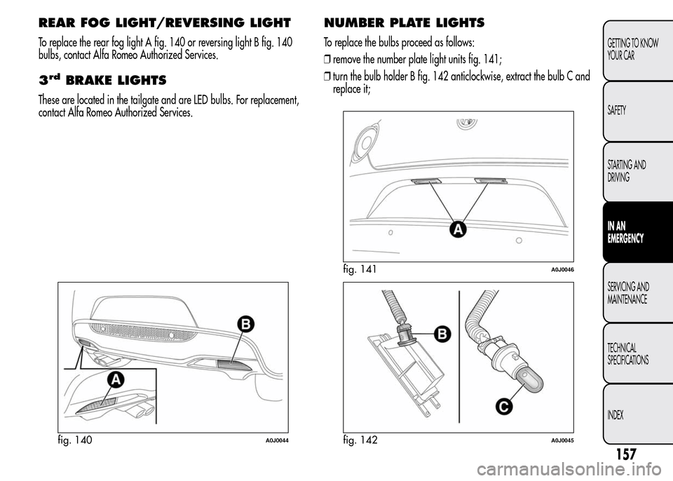
To replace the rear fog light A fig. 140 or reversing light B fig. 140
bulbs, contact Alfa Romeo Authorized Services.
3rdBRAKE LIGHTS
These are located in the tailgate and are LED bulbs. For replacement,
contact Alfa Romeo Authorized Services.
NUMBER PLATE LIGHTS
To replace the bulbs proceed as follows:
❒remove the number plate light units fig. 141;
❒turn the bulb holder B fig. 142 anticlockwise, extract the bulb C and
replace it;
fig. 140A0J0044
fig. 141A0J0046
fig. 142A0J0045
157
GETTING TO KNOW
YOUR CAR
SAFETY
STARTING AND
DRIVING
IN AN
EMERGENCY
SERVICING AND
MAINTENANCE
TECHNICAL
SPECIFICATIONS
INDEX
Page 169 of 280
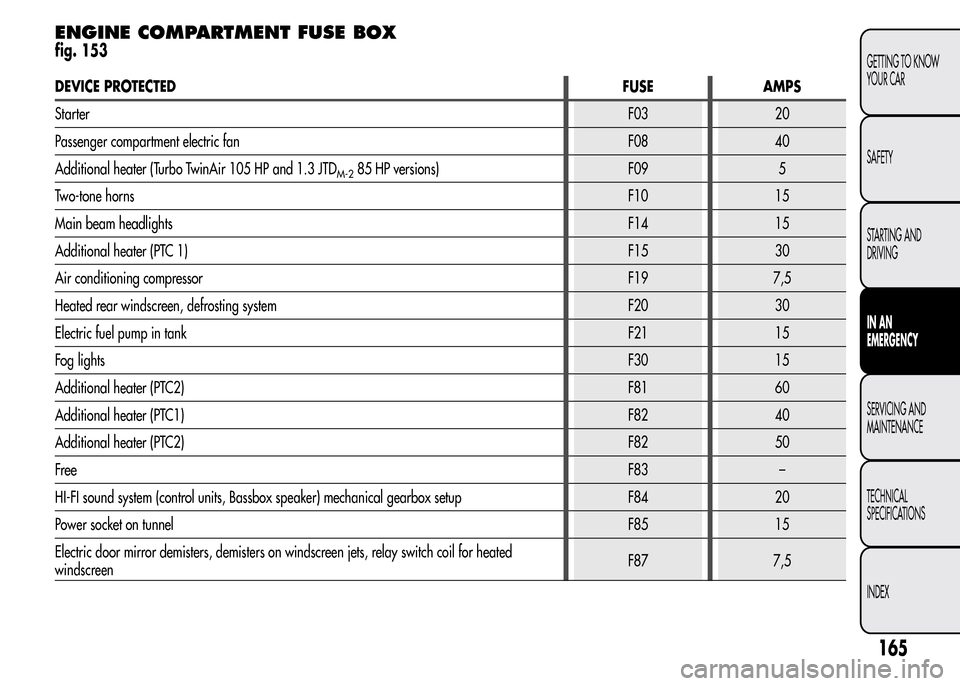
ENGINE COMPARTMENT FUSE BOX
fig. 153
DEVICE PROTECTEDFUSE AMPS
StarterF03 20
Passenger compartment electric fan F08 40
Additional heater (Turbo TwinAir 105 HP and 1.3 JTD
M-285 HP versions) F09 5
Two-tone hornsF10 15
Main beam headlightsF14 15
Additional heater (PTC 1)F15 30
Air conditioning compressorF19 7,5
Heated rear windscreen, defrosting system F20 30
Electric fuel pump in tankF21 15
Fog lightsF30 15
Additional heater (PTC2)F81 60
Additional heater (PTC1)F82 40
Additional heater (PTC2)F82 50
FreeF83 –
HI-FI sound system (control units, Bassbox speaker) mechanical gearbox setup F84 20
Power socket on tunnelF85 15
Electric door mirror demisters, demisters on windscreen jets, relay switch coil for heated
windscreenF87 7,5
165
GETTING TO KNOW
YOUR CAR
SAFETY
STARTING AND
DRIVING
IN AN
EMERGENCY
SERVICING AND
MAINTENANCE
TECHNICAL
SPECIFICATIONS
INDEX