stop start Alfa Romeo MiTo 2020 Owner handbook (in English)
[x] Cancel search | Manufacturer: ALFA ROMEO, Model Year: 2020, Model line: MiTo, Model: Alfa Romeo MiTo 2020Pages: 212, PDF Size: 5.18 MB
Page 102 of 212
INSTALLING A TOW HOOK
Contact an Alfa Romeo Dealership to
install a tow hook.
WARNING
105)The ABS with which the car is equipped
will not control the braking system of the
trailer. Particular caution is therefore
required on slippery roads.
106)Do not, under any circumstances,
modify the vehicle's braking system to
control the trailer breaking system. The
towing braking system must be completely
independent of the vehicle's hydraulic
system.
REFUELLING THE VEHICLE
During refuelling procedure, switch off
the engine, engage handbrake, rotate the
ignition key to STOP and do not smoke.
PETROL ENGINES
Only use unleaded petrol. The petrol
octane rating (RON) must not be lower
than 95. In order to prevent damage to
the catalytic converter never introduce
even the smallest amount of leaded
petrol, even in the event of an emergency.
DIESEL ENGINES
Only use diesel fuel compliant with
European specification EN590. The use
of other products or mixtures may
damage the engine beyond repair and
consequently invalidate the warranty,
due to the damage caused.
When using or parking the vehicle for a
long time in the mountains or cold areas,
it is advisable to refuel using locally
available Diesel. In this case, it is also
advisable to keep the tank over 50% full.
FUEL TANK CAP
107)
Opening
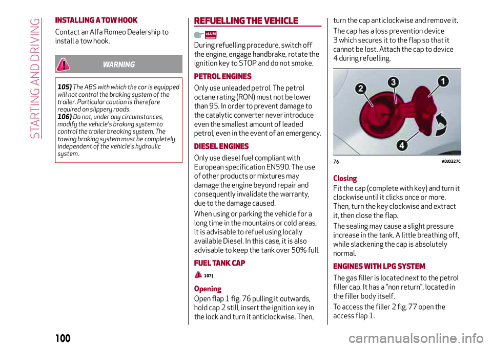
Open flap 1 fig. 76 pulling it outwards,
hold cap 2 still, insert the ignition key in
the lock and turn it anticlockwise. Then,turn the cap anticlockwise and remove it.
The cap has a loss prevention device
3 which secures it to the flap so that it
cannot be lost. Attach the cap to device
4 during refuelling.
Closing
Fit the cap (complete with key) and turn it
clockwise until it clicks once or more.
Then, turn the key clockwise and extract
it, then close the flap.
The sealing may cause a slight pressure
increase in the tank. A little breathing off,
while slackening the cap is absolutely
normal.
ENGINES WITH LPGSYSTEM
The gas filler is located next to the petrol
filler cap. It has a "non return", located in
the filler body itself.
To access the filler 2 fig. 77 open the
access flap 1.
76A0J0327C
100
STARTING AND DRIVING
Page 123 of 212
the kit from the specific compartment;
remove the adhesive label of speed 3
(see previous paragraph) and apply it in a
visible position. Wear the protective
gloves provided;
remove the cap from the valve of the
punctured tyre and connect and firmly
tighten the transparent tube of the
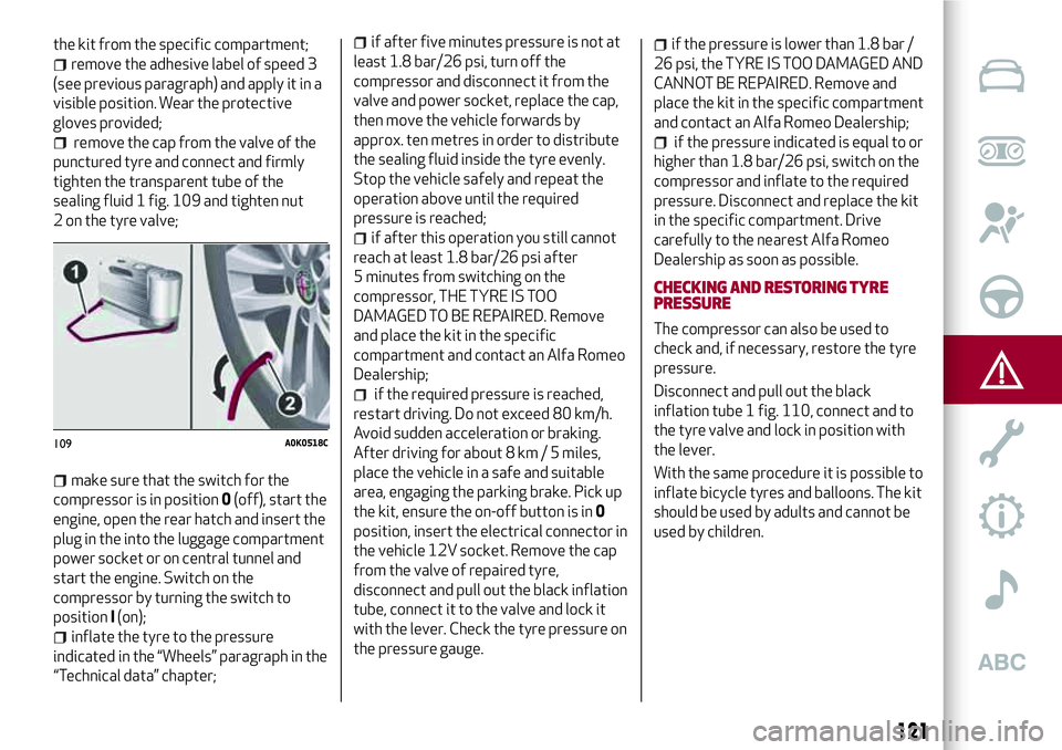
sealing fluid 1 fig. 109 and tighten nut
2 on the tyre valve;
make sure that the switch for the
compressor is in position0(off), start the
engine, open the rear hatch and insert the
plug in the into the luggage compartment
power socket or on central tunnel and
start the engine. Switch on the
compressor by turning the switch to
positionI(on);
inflate the tyre to the pressure
indicated in the “Wheels” paragraph in the
“Technical data” chapter;
if after five minutes pressure is not at
least 1.8 bar/26 psi, turn off the
compressor and disconnect it from the
valve and power socket, replace the cap,
then move the vehicle forwards by
approx. ten metres in order to distribute
the sealing fluid inside the tyre evenly.
Stop the vehicle safely and repeat the
operation above until the required
pressure is reached;
if after this operation you still cannot
reach at least 1.8 bar/26 psi after
5 minutes from switching on the
compressor, THE TYRE IS TOO
DAMAGED TO BE REPAIRED. Remove
and place the kit in the specific
compartment and contact an Alfa Romeo
Dealership;
if the required pressure is reached,
restart driving. Do not exceed 80 km/h.
Avoid sudden acceleration or braking.
After driving for about 8 km / 5 miles,
place the vehicle in a safe and suitable
area, engaging the parking brake. Pick up
the kit, ensure the on-off button is in0
position, insert the electrical connector in
the vehicle 12V socket. Remove the cap
from the valve of repaired tyre,
disconnect and pull out the black inflation
tube, connect it to the valve and lock it
with the lever. Check the tyre pressure on
the pressure gauge.
if the pressure is lower than 1.8 bar /
26 psi, the TYRE IS TOO DAMAGED AND
CANNOT BE REPAIRED. Remove and
place the kit in the specific compartment
and contact an Alfa Romeo Dealership;
if the pressure indicated is equal to or
higher than 1.8 bar/26 psi, switch on the
compressor and inflate to the required
pressure. Disconnect and replace the kit
in the specific compartment. Drive
carefully to the nearest Alfa Romeo
Dealership as soon as possible.
CHECKING AND RESTORING TYRE
PRESSURE
The compressor can also be used to
check and, if necessary, restore the tyre
pressure.
Disconnect and pull out the black
inflation tube 1 fig. 110, connect and to
the tyre valve and lock in position with
the lever.
With the same procedure it is possible to
inflate bicycle tyres and balloons. The kit
should be used by adults and cannot be
used by children.
109A0K0518C
121
Page 125 of 212
JUMP STARTING(versions with Start&Stop system)
125)
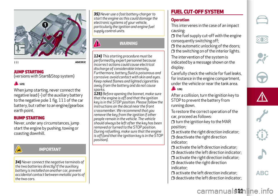
When jump starting, never connect the
negative lead (–) of the auxiliary battery
to the negative pole 1 fig. 111 of the car
battery, but rather to an engine/gearbox
earth point.
BUMP STARTING
Never, under any circumstances, jump
start the engine by pushing, towing or
coasting downhill.
IMPORTANT
34)Never connect the negative terminals of
the two batteries directly! If the auxiliary
battery is installed on another car, prevent
accidental contact between metallic parts of
the two cars.35)Never use a fast battery-charger to
start the engine as this could damage the
electronic systems of your vehicle,
particularly the ignition and engine fuel
supply control units.
WARNING
124)This starting procedure must be
performed by expert personnel because
incorrect actions could cause electrical
discharge of considerable intensity.
Furthermore, battery fluid is poisonous and
corrosive: avoid contact with skin and eyes.
Keep naked flames and lighted cigarettes
away from the battery and do not cause
sparks.
125)Before opening the bonnet, make sure
that the engine is off and that the ignition
key is in the STOP position. Please follow the
instructions on the decal near the front
crossmember. We recommend that you
remove the key from the ignition if other
people remain in the vehicle. The vehicle
should always be left after the key has been
removed or turned to the STOP position.
During refuelling, make sure that the engine
is off (and that the ignition key is in the STOP
position).
FUEL CUT-OFFSYSTEM
Operation
This intervenes in the case of an impact
causing:
the fuel supply cut-off with the engine
consequently switching off;
the automatic unlocking of the doors;
the switching on of the interior lights.
The intervention of the system is
indicated by a message shown on the
display.
Carefully check the vehicle for fuel leaks,
for instance in the engine compartment,
under the vehicle or near the tank area.
126)
After a collision, turn the ignition key to
STOP to prevent the battery from
running down.
To restore the correct operation of the
car, proceed as follows:
turn the ignition key to the MAR
position;
activate the right direction indicator;
deactivate the right direction
indicator;
activate the left direction indicator;
deactivate the left direction indicator;
activate the right direction indicator;
deactivate the right direction
indicator;
activate the left direction indicator;
deactivate the left direction indicator;
111A0J0392C
123
Page 128 of 212
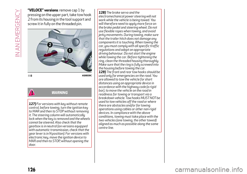
“VELOCE” versions: remove cap 1 by
pressing on the upper part, take tow hook
2 from its housing in the tool support and
screw it in fully on the threaded pin.
WARNING
127)For versions with key without remote
control, before towing, turn the ignition key
to MAR and then to STOP without removing
it. The steering column will automatically
lock when the key is removed and the wheels
cannot be steered. Also check that the
gearbox is in neutral (on versions equipped
with automatic transmission, check that the
gear lever is in N position). For versions with
electronic key, move the ignition device to
MAR and then to STOP, without opening the
door.128)The brake servo and the
electromechanical power steering will not
work while the vehicle is being towed. You
will therefore need to apply more force on
the brake pedal and steering wheel. Do not
use flexible ropes when towing, and avoid
jerky movements. During towing, make sure
that the trailer hitch does not damage any
components it is touching. When towing the
car, you must comply with all specific traffic
regulations and adopt an appropriate
driving behaviour. Do not start the engine
while towing the car. Before tightening the
ring, clean the threaded housing thoroughly.
Make sure that the ring is fully screwed into
the housing before towing the car.
129)The front and rear tow hooks should be
used only for emergencies on the road. You
are allowed to tow the vehicle for short
distances using an appropriate device in
accordance with the highway code (a rigid
bar), to move the vehicle on the road in
readiness for towing or transport via a
breakdown vehicle. Tow hooks MUST NOT be
used to tow vehicles off the road or where
there are obstacles and/or for towing
operations using cables or other non-rigid
devices. In compliance with the above
conditions, towing must take place with the
two vehicles (one towing, the other towed)
aligned as much as possible along the same
centre line.
118A0J0039C
126
IN AN EMERGENCY
Page 145 of 212
132)If the engine oil is being topped up, wait
for the engine to cool down before loosening
the filler cap, particularly for vehicles with
aluminium cap (where provided). WARNING:
risk of burns!
133)The cooling system is pressurised. If
necessary, only replace the plug with
another original or the operation of the
system may be adversely affected. Do not
remove the reservoir plug when the engine is
hot: you risk scalding yourself.
134)Do not travel with the windscreen
washer fluid reservoir empty: the
windscreen washer is essential for
improving visibility. Repeated operation of
the system without fluid could damage or
cause rapid deterioration of some system
components.
135)Some commercial additives for
windscreen washer fluid are flammable. The
engine compartment contains hot
components which may start a fire.
136)Brake fluid is poisonous and highly
corrosive. In the event of accidental contact,
immediately wash the affected parts with
water and mild soap. Then rinse thoroughly.
Call a doctor immediately if swallowed.
137)The symbol
, on the brake fluid
container indicates if a brake fluid is
synthetic or mineral-based. Use of mineral
type fluids will damage the special rubber
seals of the braking system beyond repair.
IMPORTANT
2)Used engine oil and oil filters contain
substances which are harmful to the
environment. To change the oil and filters, we
advise you to contact an Alfa Romeo
Dealership.
3)Used transmission fluid contains
substances that are harmful to the
environment. You are advised to contact an
Alfa Romeo Dealership for oil changes.
BATTERY RECHARGING
IMPORTANT The battery recharging
procedure is given as information only. To
carry out this operation contact an Alfa
Romeo Dealership.
IMPORTANT After turning the ignition
key to STOP and having closed the
driver's side door, wait at least one
minute before disconnecting and then
reconnecting the electrical supply to the
battery.
Charging should be slow at a low ampere
rating for approximately 24 hours.
Charging for a longer time may damage
the battery.
IMPORTANT The cables of the electrical
system must be correctly reconnected to
the battery, i.e. the positive cable (+) to
the positive terminal and the negative
cable (–) to the negative terminal. The
battery terminals are marked with the
positive (+) and negative (–) symbols, and
are shown on the battery cover. The
battery terminals must also be
corrosion-free and firmly secured to the
terminals. If a "quick-type" battery
charger is used with the battery fitted on
the vehicle, before connecting it
disconnect both cables of the battery
itself. Do not use a "quick-type" battery
charger to provide the starting voltage.
The cables of the electrical system must
143
Page 146 of 212
be correctly reconnected to the battery,
i.e. the positive cable (+) to the positive
terminal and the negative cable (–) to the
negative terminal. The battery terminals
are marked with the positive (+) and
negative (–) symbols, and are shown on
the battery cover. The battery terminals
must also be corrosion-free and firmly
secured to the terminals.
VERSIONS WITHOUT START&STOP
SYSTEM
(where provided)
To recharge, proceed as follows:
disconnect the terminal from the
negative battery pole;
connect the charger cables to the
battery terminals, observing the polarity;
turn on the charger;
when it is recharged, turn the charger
off before disconnecting it from the
battery;
reconnect the terminal to the negative
battery pole.
VERSIONS WITH START&STOP
SYSTEM
To recharge, proceed as follows:
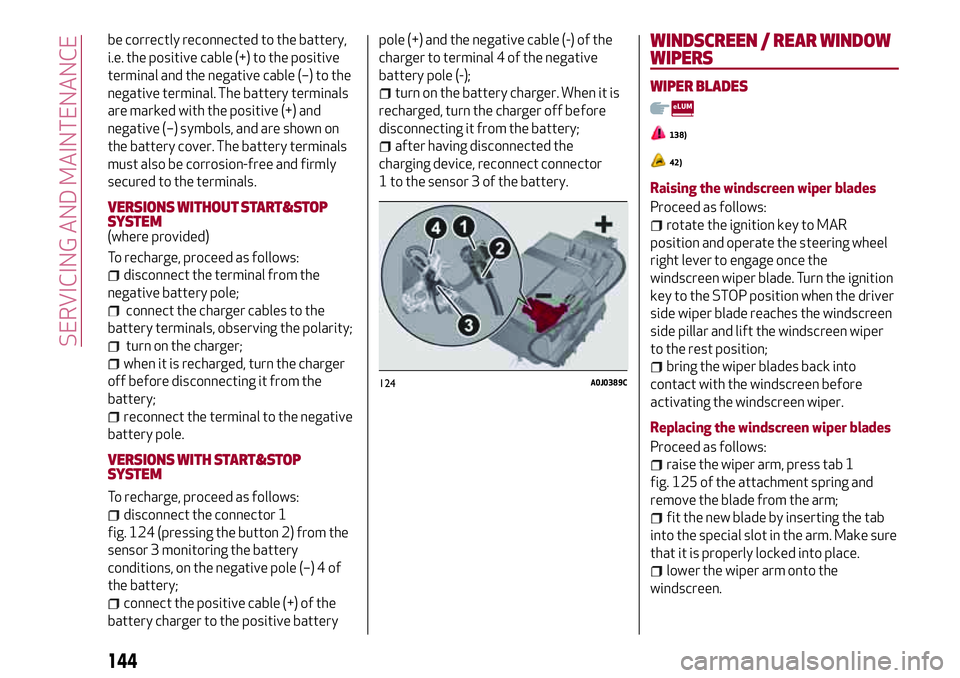
disconnect the connector 1
fig. 124 (pressing the button 2) from the
sensor 3 monitoring the battery
conditions, on the negative pole (–) 4 of
the battery;
connect the positive cable (+) of the
battery charger to the positive batterypole (+) and the negative cable (-) of the
charger to terminal 4 of the negative
battery pole (-);
turn on the battery charger. When it is
recharged, turn the charger off before
disconnecting it from the battery;
after having disconnected the
charging device, reconnect connector
1 to the sensor 3 of the battery.
WINDSCREEN / REAR WINDOW
WIPERS
WIPER BLADES
138)
42)
Raising the windscreen wiper blades
Proceed as follows:
rotate the ignition key to MAR
position and operate the steering wheel
right lever to engage once the
windscreen wiper blade. Turn the ignition
key to the STOP position when the driver
side wiper blade reaches the windscreen
side pillar and lift the windscreen wiper
to the rest position;
bring the wiper blades back into
contact with the windscreen before
activating the windscreen wiper.
Replacing the windscreen wiper blades
Proceed as follows:
raise the wiper arm, press tab 1
fig. 125 of the attachment spring and
remove the blade from the arm;
fit the new blade by inserting the tab
into the special slot in the arm. Make sure
that it is properly locked into place.
lower the wiper arm onto the
windscreen.
124A0J0389C
144
SERVICING AND MAINTENANCE
Page 189 of 212
SWITCHING THESYSTEM ON/OFF
The system is switched on/off by
pressing the
(ON/OFF) button/knob.
Turn the button/knob clockwise to
increase the radio volume or
anticlockwise to decrease it.
RADIO (TUNER) MODE
Press the RADIO button on the front
panel to activate radio mode.
Select the band by pressing the
corresponding button: “AM”, “FM” or
“DAB”.
Selecting a frequency band
Briefly press the "AM/FM" button to
switch from AM to FM and vice versa.
If the DAB tuner is available, briefly press
the "AM/FM", "AM/DAB", "FM/DAB"
buttons to select the desired band.
Indications on display
After the desired radio station is
selected, the following information is
shown on the display:
At the top: the list of radio stations
stored (presets) is displayed; the station
currently playing is highlighted.
In the middle: display of the name of the
current radio station and the buttons for
selecting the previous or next radio
station.
At the bottom:radio station selection,radio band, tuning, track information and
audio settings.
Searching for the previous/next radio
station
To search for the desired radio station,
rotate the BROWSE ENTER button/knob,
press the
orbuttons or use
the steering wheel controls
.
When searching forwards, if the system
reaches the end of the band, it will
automatically stop on the station where
the search has started from.
Previous/next radio station fast search
Hold down buttons
oron the
display: when the button is released, the
first tunable radio station will be
displayed.
Tuning the radio (AM/FM)
Press the "Tune" button on the display
and then enter the frequency of the radio
station using the keypad on the display.
In this mode, use buttons + and – to
fine-tune the frequency.
To delete an incorrect number (and enter
the correct station number) press the
(Delete) button.
After entering the last digit of the
station, the screen is deactivated and the
system tunes automatically to the
station selected (the number of the radio
station is displayed in the "Tune" text
box).The screen disappears automatically
after 5 seconds or manually by pressing
the "OK" or “X” buttons.
Exit the "Direct Tune" screen
Press the "Exit" or "Radio" button on the
display to return to the main system
screen.
DAB Radio
(where provided)
Once DAB radio mode is selected, the
information on the current station is
displayed and the following functions.
Selection of the previous/next radio
station by:
turning the BROWSE ENTER
button/knob;
briefly pressing theor
buttons on the display;
Steering wheel control press.
Hold down the
orbuttons to
fast scroll the station list.
The "Browse" button is used to display:
the list of all DAB stations;
the list of stations filtered by "Genres";
the list of stations filtered by
"Ensembles" (broadcast group).
Setting the presets
Presets are available in all system modes
and are activated by touching one of the
preset buttons located in the upper area
of the display.
If you are tuned to a radio station that
187
Page 197 of 212

IMPORTANT INFORMATION AND RECOMMENDATIONS
WARNING
INTERIOR FITTINGSDo not travel with the storage compartment open: it may injure the front seat occupants in the event of an accident.
The cigar lighter gets extremely hot. Handle it carefully and make sure that children don’t use it: risk of fire and/or burns.
Do not use the ashtray as a waste paper basket: it may catch fire in contact with cigarette stubs.
ROOF RACK/SKI RACKAfter travelling for a few kilometres, check to ensure that the fixing screws for the attachments are well tightened.
Never exceed the maximum permitted loads (see chapter "Technical specifications").
Distribute the load evenly and pay attention to side winds when driving.
ELECTRIC POWER STEERINGBefore starting any servicing operation, stop the engine and remove the key from the ignition switch to operate the steering lock,
particularly when the wheels do not touch the ground. If this is not possible (for example if the key needs to be turned to MAR or the
engine must be running), remove the main fuse that protects the electric power steering.
INTERIORNever use flammable products, such as petrol ether or rectified petrol to clean the inside of the car. The electrostatic charges
which are generated by rubbing during the cleaning operation may cause a fire.
Do not keep aerosol cans in the car: they might explode. Aerosol cans must not be exposed to a temperature exceeding 50°C.
When the vehicle is exposed to sunlight, the internal temperature can greatly exceed this value.
Page 208 of 212
Light beam direction..........34
Hill Holder system.............67
Identification data
chassis marking............153
engine marking............153
identification data plate.......152
Ignition device...............11
Installing a Universal Isofix child
restraint system............79
Instrument panel...............8
Interior lights................21
Interiors (cleaning)............149
Isofix child restraint system setup . . .79
Jack.....................116
Jump starting...............122
Keys.....................10
Key with remote control........10
Lifting the vehicle............147
Light bulbs
types of bulbs.............105
Luggage compartment
Extending the luggage
compartment..............34
Luggage compartment
initialisation...............34
Main beam headlights..........19
Main beam headlights (bulb
replacement)..............108
Mechanical key...............10
Menu items.................43MSR system................66
Multimedia
Power on/off.............187
Number plate lights (bulb
replacement)..............110
Parking lights................19
Parking sensors..............98
Parking the vehicle.............91
Passenger side front airbag.......82
Performance...............175
Pre-tensioners...............73
Load limiters..............73
Rain sensor.................22
Rear direction indicators (bulb
replacement)..............110
Rear fog light................20
Rear fog light/reversing light (bulb
replacement)..............110
Rear light clusters (bulb
replacement)..............109
Rear seat..................15
Rear view mirrors.............18
Rear window wiper/washer.......23
Reconfigurable multifunction
display................40,42
Refuelling.................169
Refuelling the vehicle..........100
Replacing a bulb.............104
exterior lights.............108
General instructions.........104Rims and tyres provided . . ......159
Safe Lock (device).............11
SBR system (Seat Belt Reminder). . . .72
Scheduled servicing . . . . . ......128
Scheduled Servicing Plan . . ......129
Screen wiper/washer . . . . . ......22
Seat belts . . . . ..............70
Seat belts (using) ..............70
Seats . . . . . . . ..............14
Servicing and maintenance
Demanding use of the car ......136
periodic checks . . . .........136
Setup menu .................43
Side airbags (Side bag - Window
bag) ....................86
Side bags (front side airbags) . . . . . .86
Side lights/brake lights (bulb
replacement). . . ...........110
Side lights/daytime running lights
(DRL) (bulb replacement) ......108
Side lights/dipped beam
headlights . . ..............19
Snow chains................164
Sport front seats ..............15
Start&Stop (system) . . . . . ......95
Starting the engine . . . . . . . . .90 ,122
Bump starting . ............123
Steering lock . . ..............11
Steering wheel . . . . ...........17
Technical data..............152
INDEX