sensor Alfa Romeo Stelvio 2018 User Guide
[x] Cancel search | Manufacturer: ALFA ROMEO, Model Year: 2018, Model line: Stelvio, Model: Alfa Romeo Stelvio 2018Pages: 276, PDF Size: 5.79 MB
Page 95 of 276
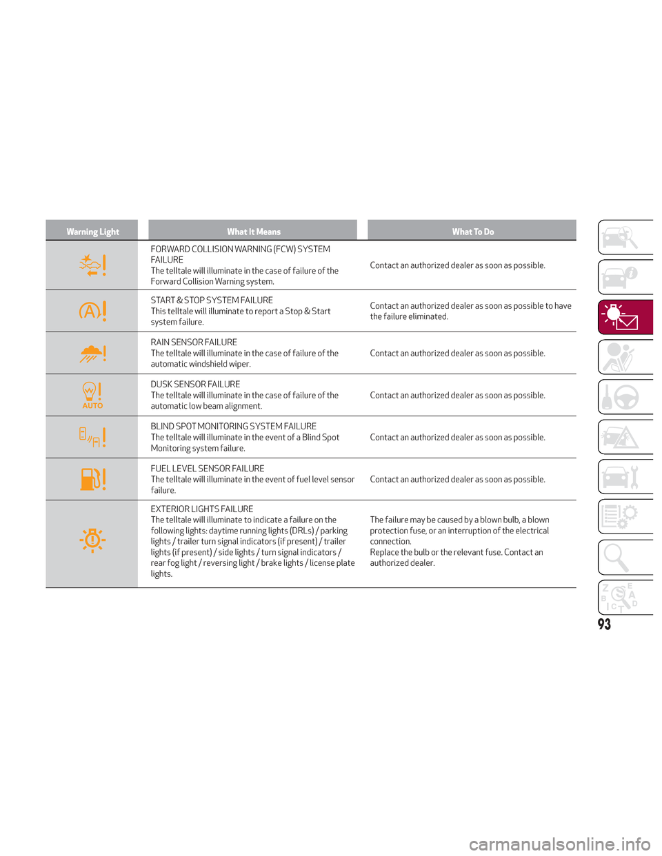
Warning LightWhat It Means What To Do
FORWARD COLLISION WARNING (FCW) SYSTEM
FAILURE
The telltale will illuminate in the case of failure of the
Forward Collision Warning system.Contact an authorized dealer as soon as possible.
START & STOP SYSTEM FAILURE
This telltale will illuminate to report a Stop & Start
system failure.Contact an authorized dealer as soon as possible to have
the failure eliminated.
RAIN SENSOR FAILURE
The telltale will illuminate in the case of failure of the
automatic windshield wiper.
Contact an authorized dealer as soon as possible.
DUSK SENSOR FAILURE
The telltale will illuminate in the case of failure of the
automatic low beam alignment.Contact an authorized dealer as soon as possible.
BLIND SPOT MONITORING SYSTEM FAILURE
The telltale will illuminate in the event of a Blind Spot
Monitoring system failure.Contact an authorized dealer as soon as possible.
FUEL LEVEL SENSOR FAILURE
The telltale will illuminate in the event of fuel level sensor
failure.Contact an authorized dealer as soon as possible.
EXTERIOR LIGHTS FAILURE
The telltale will illuminate to indicate a failure on the
following lights: daytime running lights (DRLs) / parking
lights / trailer turn signal indicators (if present) / trailer
lights (if present) / side lights / turn signal indicators /
rear fog light / reversing light / brake lights / license plate
lights.The failure may be caused by a blown bulb, a blown
protection fuse, or an interruption of the electrical
connection.
Replace the bulb or the relevant fuse. Contact an
authorized dealer.
93
Page 107 of 276
Note:
There may be a brief delay in shifting
to AWD mode after a tire slipping event
occurs.
If the system failure symbol switches
on, after starting the engine or while
driving, it means that the AWD system is
not working properly. If the warning
message activates frequently, it is
recommended to carry out the
maintenance operations.
Electronic Stability Control (ESC)
System
The ESC system improves the directional
control and stability of the vehicle in
various driving conditions.
The ESC system corrects the vehicle’s
understeer and oversteer, distributing
the brake force on the appropriate
wheels. The torque supplied by the
engine can also be reduced in order to
maintain control of the vehicle.
The ESC system uses sensors installed
on the vehicle to determine the path that
the driver intends to follow and
compares it with the vehicle’s effective
path. When the real path deviates from
the desired path, the ESC system
intervenes to counter the vehicle’s
understeer or oversteer.
Oversteer occurs when the vehicle is
turning more than it should according to
the angle of the steering wheel.
Understeer occurs when the vehicle is turning less than it should according to
the angle of the steering wheel.
System Intervention
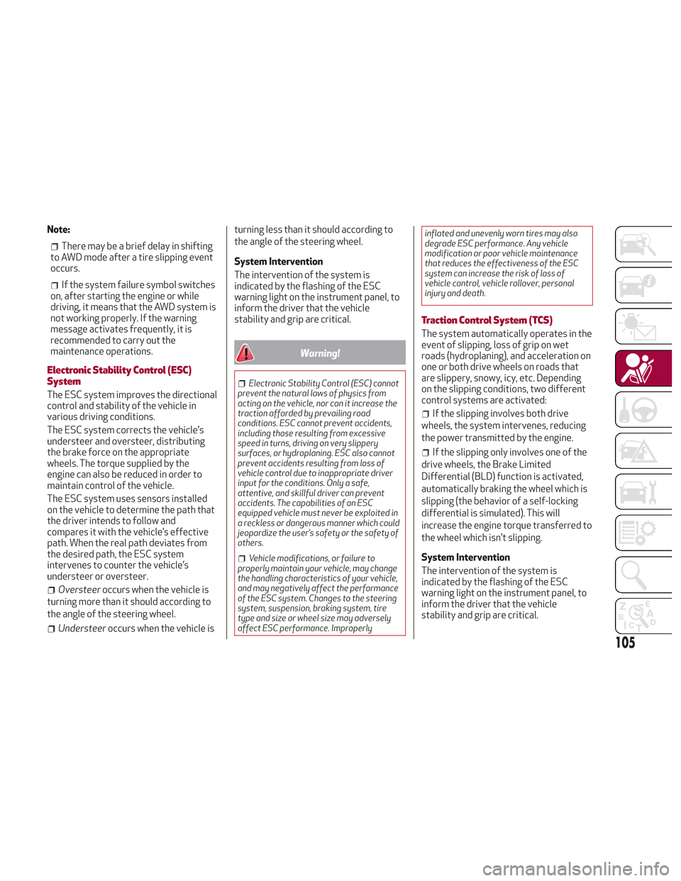
The intervention of the system is
indicated by the flashing of the ESC
warning light on the instrument panel, to
inform the driver that the vehicle
stability and grip are critical.
Warning!
Electronic Stability Control (ESC) cannot
prevent the natural laws of physics from
acting on the vehicle, nor can it increase the
traction afforded by prevailing road
conditions. ESC cannot prevent accidents,
including those resulting from excessive
speed in turns, driving on very slippery
surfaces, or hydroplaning. ESC also cannot
prevent accidents resulting from loss of
vehicle control due to inappropriate driver
input for the conditions. Only a safe,
attentive, and skillful driver can prevent
accidents. The capabilities of an ESC
equipped vehicle must never be exploited in
a reckless or dangerous manner which could
jeopardize the user’s safety or the safety of
others.
Vehicle modifications, or failure to
properly maintain your vehicle, may change
the handling characteristics of your vehicle,
and may negatively affect the performance
of the ESC system. Changes to the steering
system, suspension, braking system, tire
type and size or wheel size may adversely
affect ESC performance. Improperly inflated and unevenly worn tires may also
degrade ESC performance. Any vehicle
modification or poor vehicle maintenance
that reduces the effectiveness of the ESC
system can increase the risk of loss of
vehicle control, vehicle rollover, personal
injury and death.
Traction Control System (TCS)
The system automatically operates in the
event of slipping, loss of grip on wet
roads (hydroplaning), and acceleration on
one or both drive wheels on roads that
are slippery, snowy, icy, etc. Depending
on the slipping conditions, two different
control systems are activated:
If the slipping involves both drive
wheels, the system intervenes, reducing
the power transmitted by the engine.
If the slipping only involves one of the
drive wheels, the Brake Limited
Differential (BLD) function is activated,
automatically braking the wheel which is
slipping (the behavior of a self-locking
differential is simulated). This will
increase the engine torque transferred to
the wheel which isn't slipping.
System Intervention
The intervention of the system is
indicated by the flashing of the ESC
warning light on the instrument panel, to
inform the driver that the vehicle
stability and grip are critical.
105
Page 109 of 276
Dynamic Steering Torque (DST) System
The DST function uses the integration of
the ESC system with the electric power
steering to increase the safety level of
the whole vehicle.
In critical situations for example (braking
on surfaces with different grip
conditions), the ESC system influences
the steering through the DST function to
implement an additional torque
contribution on the steering wheel in
order to suggest the most correct
maneuver to the driver.
The coordinated action of the brakes and
steering increases the safety and control
of the vehicle.
Note:The DST feature is only meant to
help the driver realize the correct course
of action through small torques on the
steering wheel, which means the
effectiveness of the DST feature is highly
dependent on the driver’s sensitivity and
overall reaction to the applied torque. It
is very important to realize that this
feature will not steer the vehicle,
meaning the driver is still responsible for
steering the vehicle.
Active Torque Vectoring (ATV) System
The dynamic drive control is used to
optimize and balance the drive torque
between the wheels of the same axles.
The ATV system improves the grip in
turns, sending more drive torque to the
external wheel.
Given that, in a turn, the external wheels
of the car travel more than the internal
ones and therefore turn faster, sending a
higher thrust to the external rear wheel
allows for the car to be more stable and
to not suffer an "understeer" condition.
Understeer occurs when the vehicle is
turning less than appropriate for the
steering wheel position.
AUXILIARY DRIVING SYSTEMS
The following auxiliary driving systems
are available in this vehicle:
Blind Spot Monitoring (BSM)
Forward Collision Warning Plus
(FCW+)
Tire Pressure Monitoring System
(TPMS)
Blind Spot Monitoring (BSM) System
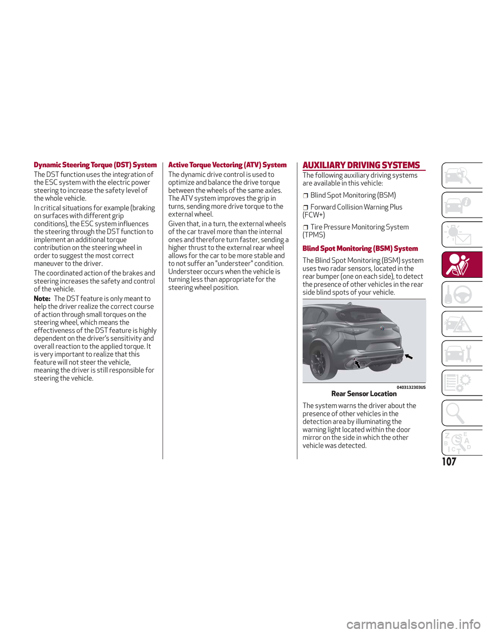
The Blind Spot Monitoring (BSM) system
uses two radar sensors, located in the
rear bumper (one on each side), to detect
the presence of other vehicles in the rear
side blind spots of your vehicle.
The system warns the driver about the
presence of other vehicles in the
detection area by illuminating the
warning light located within the door
mirror on the side in which the other
vehicle was detected.
0403132303USRear Sensor Location
107
Page 110 of 276
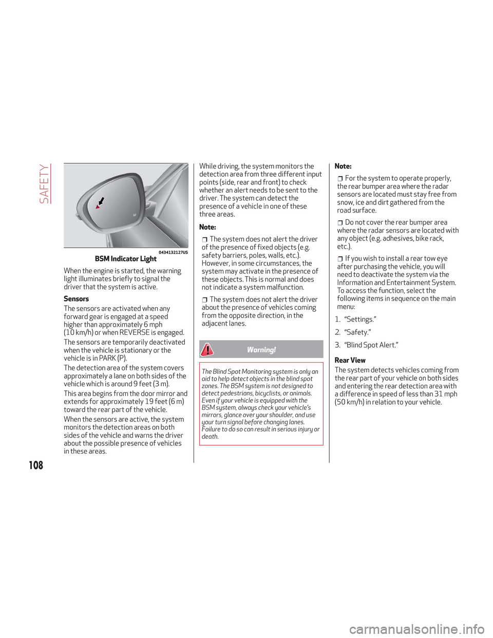
When the engine is started, the warning
light illuminates briefly to signal the
driver that the system is active.
Sensors
The sensors are activated when any
forward gear is engaged at a speed
higher than approximately 6 mph
(10 km/h) or when REVERSE is engaged.
The sensors are temporarily deactivated
when the vehicle is stationary or the
vehicle is in PARK (P).
The detection area of the system covers
approximately a lane on both sides of the
vehicle which is around 9 feet (3 m).
This area begins from the door mirror and
extends for approximately 19 feet (6 m)
toward the rear part of the vehicle.
When the sensors are active, the system
monitors the detection areas on both
sides of the vehicle and warns the driver
about the possible presence of vehicles
in these areas.While driving, the system monitors the
detection area from three different input
points (side, rear and front) to check
whether an alert needs to be sent to the
driver. The system can detect the
presence of a vehicle in one of these
three areas.
Note:
The system does not alert the driver
of the presence of fixed objects (e.g.
safety barriers, poles, walls, etc.).
However, in some circumstances, the
system may activate in the presence of
these objects. This is normal and does
not indicate a system malfunction.
The system does not alert the driver
about the presence of vehicles coming
from the opposite direction, in the
adjacent lanes.
Warning!
The Blind Spot Monitoring system is only an
aid to help detect objects in the blind spot
zones. The BSM system is not designed to
detect pedestrians, bicyclists, or animals.
Even if your vehicle is equipped with the
BSM system, always check your vehicle’s
mirrors, glance over your shoulder, and use
your turn signal before changing lanes.
Failure to do so can result in serious injury or
death.
Note:
For the system to operate properly,
the rear bumper area where the radar
sensors are located must stay free from
snow, ice and dirt gathered from the
road surface.
Do not cover the rear bumper area
where the radar sensors are located with
any object (e.g. adhesives, bike rack,
etc.).
If you wish to install a rear tow eye
after purchasing the vehicle, you will
need to deactivate the system via the
Information and Entertainment System.
To access the function, select the
following items in sequence on the main
menu:
1. “Settings.”
2. “Safety.”
3. “Blind Spot Alert.”
Rear View
The system detects vehicles coming from
the rear part of your vehicle on both sides
and entering the rear detection area with
a difference in speed of less than 31 mph
(50 km/h) in relation to your vehicle.0434132127USBSM Indicator Light
108
SAFETY
Page 111 of 276
Overtaking Vehicles
If another vehicle is overtaken slowly,
with a difference in speed of less than
approximately 15 mph (25 km/h) and the
vehicle stays in the blind spot for
approximately 1.5 seconds, the warning
light on the door mirror of the
corresponding side illuminates.
If the difference in speed between the
two vehicles is greater than
approximately 15 mph (25 km/h), the
warning light does not illuminate.
Rear Cross Path Detection (RCP)
System
This system assists the driver during
reverse maneuvers in the case of reduced
visibility.
The RCP system monitors the rear
detection areas on both sides of the
vehicle to detect objects moving toward
the sides of the vehicle, with a minimum
speed between approximately 1 mph
(1 km/h) and 2 mph (3 km/h) and objects
moving at a maximum speed of 21 mph
(35 km/h), in areas such as parking lots.
The system activation is signaled to the
driver by an audible warning.
Note:If the sensors are covered by
objects or vehicles, the system may not
work as intended.
Warning!
Rear Cross Path Detection (RCP) is not a
back up aid system. It is intended to be used
to help a driver detect an oncoming vehicle in
a parking lot situation. Drivers must be
careful when backing up, even when using
RCP. Always check carefully behind your
vehicle, look behind you, and be sure to check
for pedestrians, animals, other vehicles,
obstructions, and blind spots before backing
up. Failure to do so can result in serious
injury or death.
Operating Mode
The system may be activated/
deactivated via the Information and
Entertainment System. To access the
function, select the following items on
the main menu in sequence:
1. “Settings.”
2. “Safety.”
3. “Blind Spot Alert.”
"Blind Spot Alert", "Visual" Mode
When the system is enabled, the warning
light within the door mirror on the side of
the detected object illuminates.
The visual warning on the mirror will blink
if the driver activates the turn signals,
thus indicating the intention to change
lane. The warning light will be constant if the
driver stays in the same lane.
"Blind Spot Alert" Function
Deactivation
When the system is deactivated ("Blind
Spot Alert" mode off), the BSM or RCP
systems will not emit neither an acoustic
nor visual warning.
The BSM system will store the operating
mode that was active when the engine
was stopped. Each time the engine is
started, the operating mode last set will
be recalled and used.
General Information
This vehicle has systems that operate on
radio frequency that comply with Part
15 of the Federal Communications
Commission (FCC) rules and with
Industry Canada Standards RSS-
GEN/210/220/310.
Operation is subject to the following two
conditions:
1. The device may not cause harmful
interference.
2. The device must accept any
interference received, including
interference that may cause undesired
operation of the device.
Changes or modifications to any of these
systems by other than an authorized
service facility could void authorization
to use this equipment.
109
Page 114 of 276
Radar Indication Not Available
If conditions are such that the radar
cannot detect obstacles correctly, the
system is deactivated and a dedicated
message appears on the display. This
generally occurs in the event of poor
visibility, such as when it is snowing or
raining heavily.
The function of this system can also be
temporarily reduced due to obstructions
such as mud, dirt or ice on the bumper. In
such cases, a dedicated message will be
shown on the display and the system will
be deactivated. This message can
sometimes appear in conditions of high
reflectivity (e.g. tunnels with reflective
tiles or ice or snow). When the conditions
limiting the system functions end, it will
go back to normal and complete
operation.
In certain cases, this dedicated message
could be displayed when the radar is not
detecting any vehicles or objects within
its view range.
If atmospheric conditions are not the
reason behind this message, check if the
sensor is dirty. It could be necessary to
clean or remove any obstructions in the
area.If the message appears frequently, even
in the absence of atmospheric conditions
such as snow, rain, mud or other
obstructions, contact your authorized
dealer for a sensor alignment check.
In the absence of visible obstructions,
manually removing the decorative cover
trim and cleaning the radar surface could
be required. Have this operation
performed at your authorized dealer.
Note:
It is recommended that you do not
install devices, accessories or
aerodynamic attachments in front of the
sensor or darken it in any way, as this can
compromise the correct functioning of
the system.
Frontal Collision Alarm With Active
Braking
If this function is selected, the brakes are
operated to reduce the speed of the
vehicle in the event of potential frontal
impact.
This function applies an additional
braking pressure if the braking pressure
applied by the driver does not suffice to
prevent potential frontal impact.
The function is active with speed above
4 mph (7 km/h).
Driving In Special Conditions
In certain driving conditions, system
intervention might be unexpected or
delayed. The driver must therefore be
very careful, keeping control of the
vehicle to drive in complete safety.Driving close to a bend.
The vehicle ahead is leaving a
roundabout.
Vehicles with small dimensions and/or
not aligned in the driving lane.
Lane change by other vehicles.
Vehicles traveling at right angles to the
vehicle.
Note: In particularly complex traffic
conditions, the driver can deactivate the
system manually through the Information
and Entertainment System.
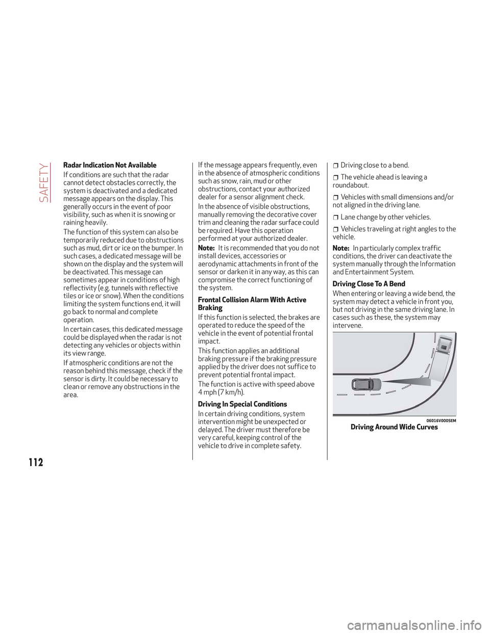
Driving Close To A Bend
When entering or leaving a wide bend, the
system may detect a vehicle in front you,
but not driving in the same driving lane. In
cases such as these, the system may
intervene.
06016V0005EMDriving Around Wide Curves
112
SAFETY
Page 115 of 276
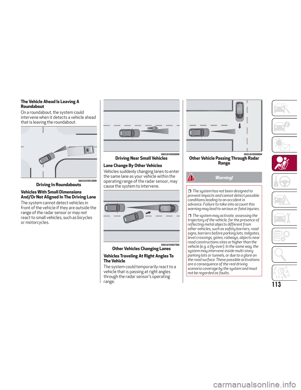
The Vehicle Ahead Is Leaving A
Roundabout
On a roundabout, the system could
intervene when it detects a vehicle ahead
that is leaving the roundabout.
Vehicles With Small Dimensions
And/Or Not Aligned In The Driving Lane
The system cannot detect vehicles in
front of the vehicle if they are outside the
range of the radar sensor or may not
react to small vehicles, such as bicycles
or motorcycles.Lane Change By Other Vehicles
Vehicles suddenly changing lanes to enter
the same lane as your vehicle within the
operating range of the radar sensor, may
cause the system to intervene.
Vehicles Traveling At Right Angles To
The Vehicle
The system could temporarily react to a
vehicle that is passing at right angles
through the radar sensor’s operating
range.
Warning!
The system has not been designed to
prevent impacts and cannot detect possible
conditions leading to an accident in
advance. Failure to take into account this
warning may lead to serious or fatal injuries.
The system may activate, assessing the
trajectory of the vehicle, for the presence of
reflecting metal objects different from
other vehicles, such as safety barriers, road
signs, barriers before parking lots, tollgates,
level crossings, gates, railways, objects near
road constructions sites or higher than the
vehicle (e.g. a fly-over). In the same way, the
system may intervene inside multi-story
parking lots or tunnels, or due to a glare on
the road surface. These possible activations
are a consequence of the real driving
scenario coverage by the system and must
not be regarded as faults.
06016V0010EMDriving In Roundabouts
06016V0006EMDriving Near Small Vehicles
06016V0007EMOther Vehicles Changing Lanes
06016V0008EMOther Vehicle Passing Through Radar Range
113
Page 117 of 276
Caution!
The TPMS has been optimized for the
original equipment tires and wheels. TPMS
pressures and warning have been
established for the tire size equipped on
your vehicle. Undesirable system operation
or sensor damage may result when using
replacement equipment that is not of the
same size, type, and/or style. The TPM
sensor is not designed for use on
aftermarket wheels and may contribute to a
poor overall system performance or sensor
damage. Customers are encouraged to use
OEM wheels to assure proper TPM feature
operation.
Using aftermarket tire sealants may
cause the Tire Pressure Monitoring System
(TPMS) sensor to become inoperable. After
using an aftermarket tire sealant it is
recommended that you take your vehicle to
your authorized dealer to have your sensor
function checked.
After inspecting or adjusting the tire
pressure always reinstall the valve stem
cap. This will prevent moisture and dirt from
entering the valve stem, which could
damage the TPMS sensor.
Insufficient Tire Pressure Indication
If an insufficient pressure value is
detected on one or more tires, the
warning light in the instrument cluster
will display alongside the dedicated
messages, the system will highlight the
tire or tires with insufficient pressure
graphically, and an acoustic signal will be
emitted.
In this case, stop the vehicle, check the
inflation pressure of each tire, and inflate
the necessary tire or tires to the correct
cold inflation pressure value, shown on
the display or in the dedicated TPMS
menu.
TPMS Temporarily Disabled:
TPMS Check Message
When a system fault is detected, the “Tire
Pressure Monitoring Warning Light” will
flash on and off for 75 seconds, and then
remain on solid. The system fault will also
sound a chime. If the ignition is cycled,
this sequence will repeat, provided that
the system fault still exists. The “Tire
Pressure Monitoring Warning Light” will
turn off when the fault condition no
longer exists. A system fault can occur
due to any of the following:
Jamming due to electronic devices or
driving next to facilities emitting the
same radio frequencies as the TPMS
sensors.
Installing some form of aftermarket
window tinting that affects radio wave
signals.
Packed snow or ice around the wheels
or wheel housings.
Using tire chains on the vehicle.
Using wheels/tires not equipped with
TPMS sensors.
After the punctured tire has been
repaired with the original tire sealant
contained in the TireKit, the previous
condition must be restored so that the
warning light is off during normal
driving.
TPMS Deactivation
The TPMS can be deactivated by
replacing all four wheel and tire
assemblies (road tires) with wheel and
tire assemblies that do not have TPMS
Sensors, such as when installing winter
wheel and tire assemblies on your
vehicle.
To deactivate the TPMS, first replace all
four wheel and tire assemblies (road
tires) with tires not equipped with Tire
Pressure Monitoring (TPM) Sensors.
Then, drive the vehicle for 20 minutes
above 15 mph (24 km/h). The TPMS will
chime, the "TPMS Warning Light" will
flash on and off for 75 seconds and then
remain on. The instrument cluster will
display the “SERVICE TPM SYSTEM”
message and then display dashes (--) in
place of the pressure values.
115
Page 118 of 276
Beginning with the next ignition switch
cycle, the TPMS will no longer chime or
display the “SERVICE TPM SYSTEM”
message in the instrument cluster.
Instead, dashes (--) will remain in place of
the pressure values.
To reactivate the TPMS, replace all four
wheel and tire assemblies (road tires)
with tires equipped with TPM sensors.
Then, drive the vehicle for up to
20 minutes above 15 mph (24 km/h). The
TPMS will chime, the "TPM Warning
Light" will flash on and off for 75 seconds
and then turn off. The instrument cluster
will display the “SERVICE TPM SYSTEM”
message and then display pressure
values in place of the dashes. On the next
ignition switch cycle the "SERVICE TPM
SYSTEM" message will no longer be
displayed, as long as no system fault
exists.Note:
The TPMS is not intended to replace
normal tire care and maintenance, or to
provide warning of a tire failure or
condition.
The TPMS should not be used as a
tire pressure gauge while adjusting your
tire pressure.
Driving on a significantly
underinflated tire will cause the tire to
overheat, and can lead to tire failure.
Underinflation also reduces fuel
efficiency and tire tread life, and may
affect the vehicle’s handling and
stopping ability.
The TPMS is not a substitute for
proper tire maintenance, and it is the
driver’s responsibility to maintain
correct tire pressure using an accurate
tire pressure gauge, even if
underinflation has not reached the level
to trigger illumination of the “Tire
Pressure Monitoring Warning Light”.
Seasonal temperature changes will
affect tire pressure, and the TPMS will
monitor the actual tire pressure in the
tire.
General Information
The following regulatory statement
applies to all radio frequency (RF)
devices equipped in this vehicle:
This device complies with Part 15 of the
FCC rules and RSS-210 of Industry
Canada. Operation is subject to the
following two conditions:
(1) This device may not cause harmful
interference.
(2) This device must accept any
interference received, including
interference that may cause undesired
operation.
Note: Changes or modifications not
expressly approved by the party
responsible for compliance could void the
user’s authority to operate the
equipment.
116
SAFETY
Page 124 of 276
webbing to retract completely in this
case and then carefully pull out only the
amount of webbing necessary to
comfortably wrap around the occupant’s
mid-section. Slide the latch plate into the
buckle until you hear a "click."
In Automatic Locking Mode, the shoulder
belt is automatically pre-locked. The seat
belt will still retract to remove any slack
in the shoulder belt. Use the Automatic
Locking Mode anytime a child restraint is
installed in a seating position that has a
seat belt with this feature. Children
12 years old and under should always be
properly restrained in the rear seat of a
vehicle with a rear seat.
Warning!
Never place a rear-facing child restraint in
front of an air bag. A deploying passenger
front air bag can cause death or serious
injury to a child 12 years or younger,
including a child in a rear-facing child
restraint.
Only use a rear-facing child restraint in
the rear seat of a vehicle with a rear seat.
How To Engage The Automatic Locking
Mode
1. Buckle the combination lap and
shoulder belt. 2. Grasp the shoulder portion and pull
downward until the entire seat belt is
extracted.
3. Allow the seat belt to retract. As the
seat belt retracts, you will hear a clicking
sound. This indicates the seat belt is now
in the Automatic Locking Mode.
How To Disengage The Automatic
Locking Mode
Unbuckle the combination lap/shoulder
belt and allow it to retract completely to
disengage the Automatic Locking Mode
and activate the vehicle sensitive
(emergency) locking mode.
Warning!
The seat belt assembly must be replaced
if the switchable Automatic Locking
Retractor (ALR) feature or any other seat
belt function is not working properly when
checked according to the procedures in the
Service Manual.
Failure to replace the seat belt assembly
could increase the risk of injury in collisions.
Do not use the Automatic Locking Mode
to restrain occupants who are wearing the
seat belt or children who are using booster
seats. The locked mode is only used to
install rear-facing or forward-facing child
restraints that have a harness for
restraining the child.
Supplemental Restraint Systems
(SRS)
Some of the safety features described in
this section may be standard equipment
on some models, or may be optional
equipment on others. If you are not sure,
ask your authorized dealer.
The air bag system must be ready to
protect you in a collision. The Occupant
Restraint Controller (ORC) monitors the
internal circuits and interconnecting
wiring associated with the electrical Air
Bag System Components. Your vehicle
may be equipped with the following Air
Bag System Components:
Air Bag System Components
Occupant Restraint Controller (ORC)
Air Bag Warning Light
Steering Wheel and Column
Instrument Panel
Knee Impact Bolsters
Driver and Front Passenger Air Bags
Seat Belt Buckle Switch
Supplemental Side Air Bags
Supplemental Knee Air Bags
Front and Side Impact Sensors
Seat Belt Pretensioners
Seat Track Position Sensors
122
SAFETY