Alfa Romeo Stelvio 2018 Owner's Manual
Manufacturer: ALFA ROMEO, Model Year: 2018, Model line: Stelvio, Model: Alfa Romeo Stelvio 2018Pages: 276, PDF Size: 5.79 MB
Page 191 of 276
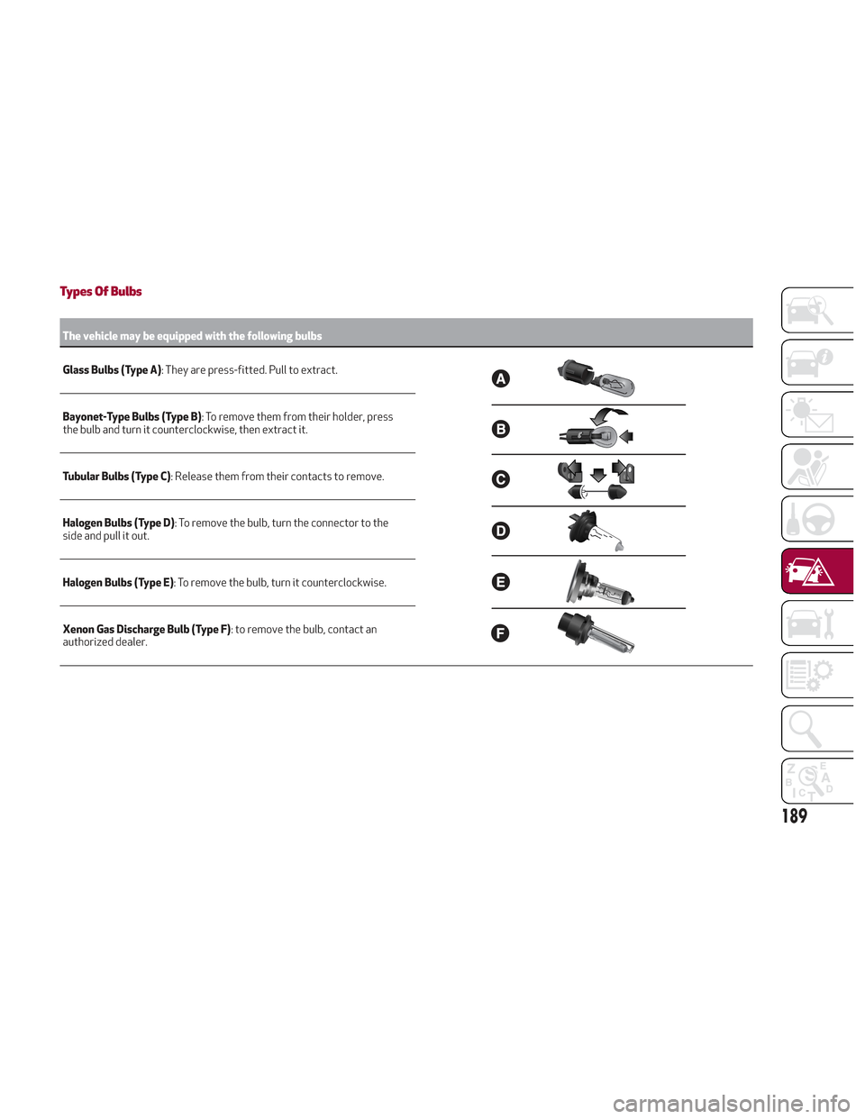
Types Of Bulbs
The vehicle may be equipped with the following bulbs
Glass Bulbs (Type A):
They are press-fitted. Pull to extract.
Bayonet-Type Bulbs (Type B) : To remove them from their holder, press
the bulb and turn it counterclockwise, then extract it.
Tubular Bulbs (Type C) : Release them from their contacts to remove.
Halogen Bulbs (Type D) : To remove the bulb, turn the connector to the
side and pull it out.
Halogen Bulbs (Type E) : To remove the bulb, turn it counterclockwise.
Xenon Gas Discharge Bulb (Type F) : to remove the bulb, contact an
authorized dealer.
189
Page 192 of 276
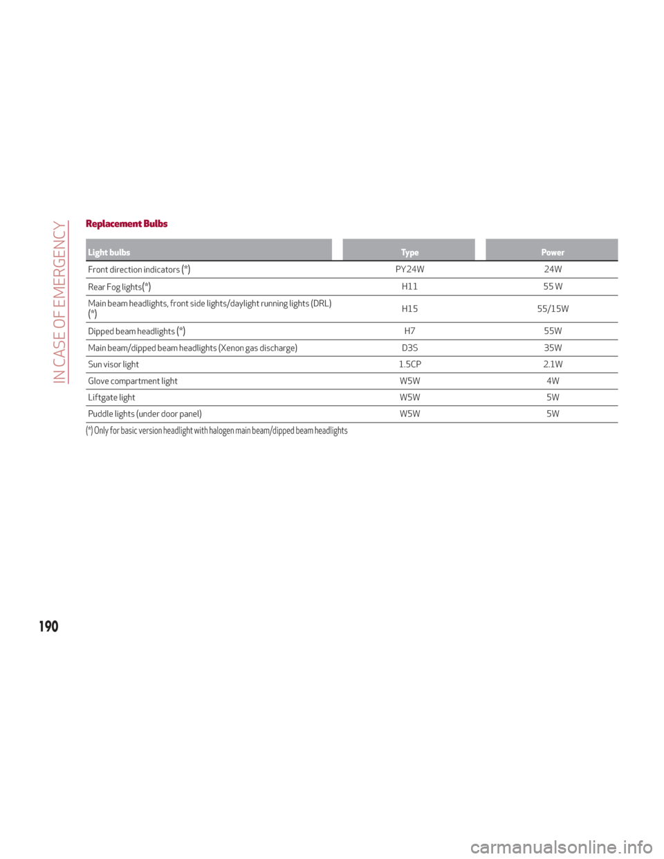
Replacement Bulbs
Light bulbsTypePower
Front direction indicators
(*)PY24W 24W
Rear Fog lights
(*)H11 55 W
Main beam headlights, front side lights/daylight running lights (DRL)
(*)H15 55/15W
Dipped beam headlights
(*)H7 55W
Main beam/dipped beam headlights (Xenon gas discharge) D3S35W
Sun visor light 1.5CP2.1W
Glove compartment light W5W4W
Liftgate light W5W5W
Puddle lights (under door panel) W5W5W
(*) Only for basic version headlight with halogen main beam/dipped beam headlights
190
IN CASE OF EMERGENCY
Page 193 of 276
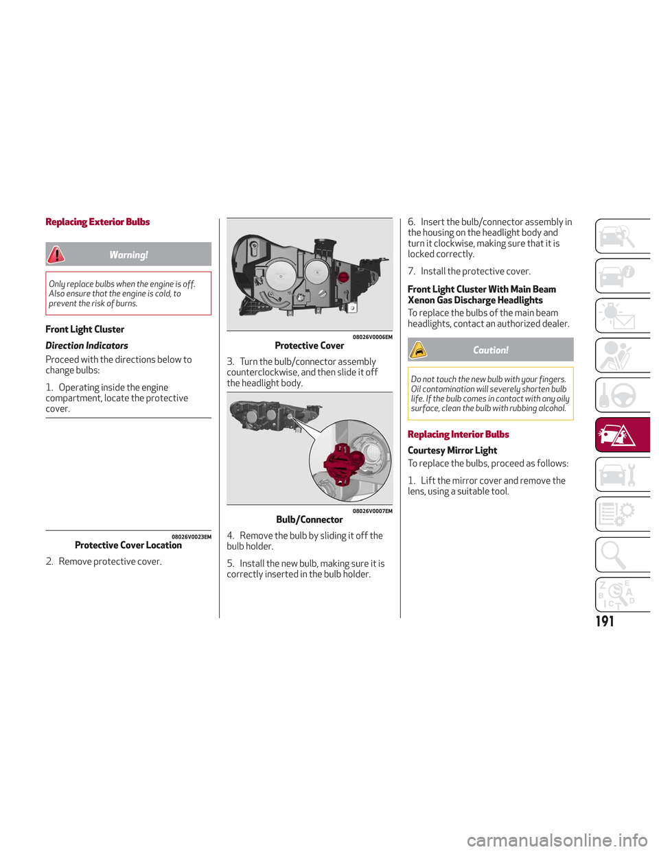
Replacing Exterior Bulbs
Warning!
Only replace bulbs when the engine is off.
Also ensure that the engine is cold, to
prevent the risk of burns.
Front Light Cluster
Direction Indicators
Proceed with the directions below to
change bulbs:
1. Operating inside the engine
compartment, locate the protective
cover.
2. Remove protective cover.3. Turn the bulb/connector assembly
counterclockwise, and then slide it off
the headlight body.
4. Remove the bulb by sliding it off the
bulb holder.
5. Install the new bulb, making sure it is
correctly inserted in the bulb holder.6. Insert the bulb/connector assembly in
the housing on the headlight body and
turn it clockwise, making sure that it is
locked correctly.
7. Install the protective cover.
Front Light Cluster With Main Beam
Xenon Gas Discharge Headlights
To replace the bulbs of the main beam
headlights, contact an authorized dealer.
Caution!
Do not touch the new bulb with your fingers.
Oil contamination will severely shorten bulb
life. If the bulb comes in contact with any oily
surface, clean the bulb with rubbing alcohol.
Replacing Interior Bulbs
Courtesy Mirror Light
To replace the bulbs, proceed as follows:
1. Lift the mirror cover and remove the
lens, using a suitable tool.
08026V0023EMProtective Cover Location
08026V0006EMProtective Cover
08026V0007EMBulb/Connector
191
Page 194 of 276
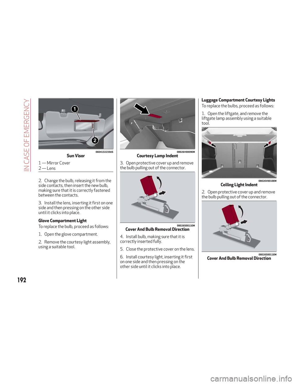
2. Change the bulb, releasing it from the
side contacts, then insert the new bulb,
making sure that it is correctly fastened
between the contacts.
3. Install the lens, inserting it first on one
side and then pressing on the other side
until it clicks into place.
Glove Compartment Light
To replace the bulb, proceed as follows:
1. Open the glove compartment.
2. Remove the courtesy light assembly,
using a suitable tool.3. Open protective cover up and remove
the bulb pulling out of the connector.
4. Install bulb, making sure that it is
correctly inserted fully.
5. Close the protective cover on the lens.
6. Install courtesy light, inserting it first
on one side and then pressing on the
other side until it clicks into place.Luggage Compartment Courtesy Lights
To replace the bulbs, proceed as follows:
1. Open the liftgate, and remove the
liftgate lamp assembly using a suitable
tool.
2. Open protective cover up and remove
the bulb pulling out of the connector.
0604132233USSun Visor
1 — Mirror Cover
2 — Lens
08026V0009EMCourtesy Lamp Indent
08026S0011EMCover And Bulb Removal Direction
08026V0010EMCeiling Light Indent
08026S0011EMCover And Bulb Removal Direction
192
IN CASE OF EMERGENCY
Page 195 of 276
3. Install bulb, making sure that it is
correctly inserted fully.
4. Close the protective cover on the lens.
5. Install liftgate lamp in the correct
position, inserting it first on one side, and
then pressing on the other side until it
clicks into place.
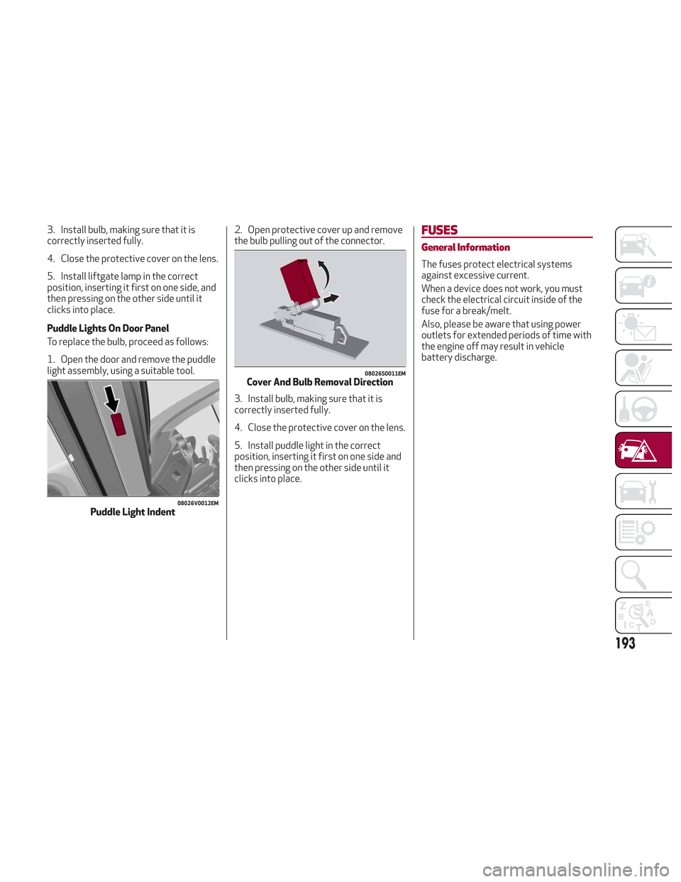
Puddle Lights On Door Panel
To replace the bulb, proceed as follows:
1. Open the door and remove the puddle
light assembly, using a suitable tool.2. Open protective cover up and remove
the bulb pulling out of the connector.
3. Install bulb, making sure that it is
correctly inserted fully.
4. Close the protective cover on the lens.
5. Install puddle light in the correct
position, inserting it first on one side and
then pressing on the other side until it
clicks into place.FUSES
General Information
The fuses protect electrical systems
against excessive current.
When a device does not work, you must
check the electrical circuit inside of the
fuse for a break/melt.
Also, please be aware that using power
outlets for extended periods of time with
the engine off may result in vehicle
battery discharge.
08026V0012EMPuddle Light Indent
08026S0011EMCover And Bulb Removal Direction
193
Page 196 of 276
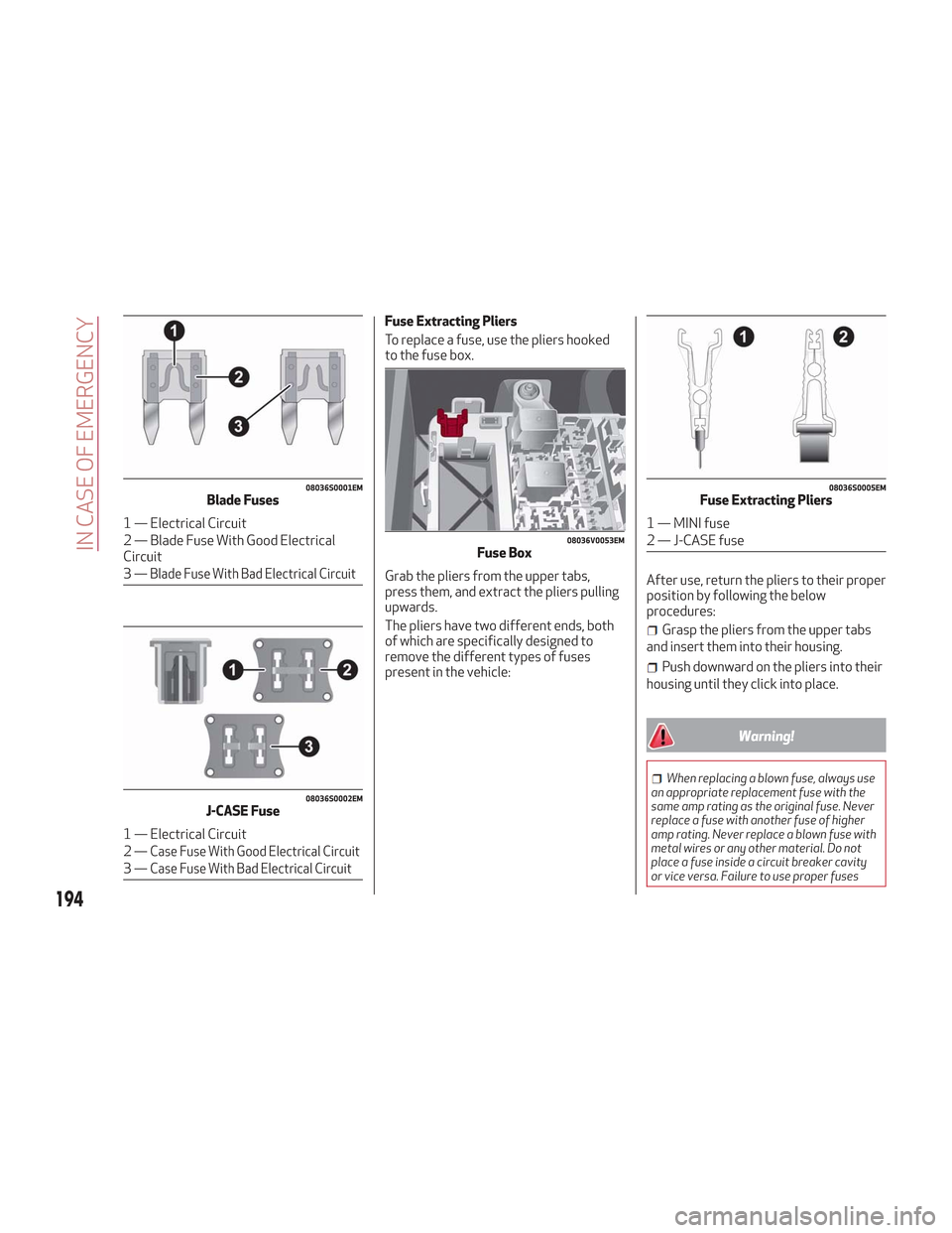
Fuse Extracting Pliers
To replace a fuse, use the pliers hooked
to the fuse box.
Grab the pliers from the upper tabs,
press them, and extract the pliers pulling
upwards.
The pliers have two different ends, both
of which are specifically designed to
remove the different types of fuses
present in the vehicle:After use, return the pliers to their proper
position by following the below
procedures:
Grasp the pliers from the upper tabs
and insert them into their housing.
Push downward on the pliers into their
housing until they click into place.
Warning!
When replacing a blown fuse, always use
an appropriate replacement fuse with the
same amp rating as the original fuse. Never
replace a fuse with another fuse of higher
amp rating. Never replace a blown fuse with
metal wires or any other material. Do not
place a fuse inside a circuit breaker cavity
or vice versa. Failure to use proper fuses
08036S0001EMBlade Fuses
1 — Electrical Circuit
2 — Blade Fuse With Good Electrical
Circuit
3—
Blade Fuse With Bad Electrical Circuit
08036S0002EMJ-CASE Fuse
1 — Electrical Circuit
2—
Case Fuse With Good Electrical Circuit
3—Case Fuse With Bad Electrical Circuit
08036V0053EMFuse Box
08036S0005EMFuse Extracting Pliers
1 — MINI fuse
2 — J-CASE fuse
194
IN CASE OF EMERGENCY
Page 197 of 276
may result in serious personal injury, fire
and/or property damage.
Before replacing a fuse, make sure that
the ignition is off and that all the other
services are switched off and/or
disengaged.
If the replaced fuse blows again, contact
an authorized dealer.
If a general protection fuse for safety
systems (air bag system, braking system),
power unit systems (engine system,
transmission system) or steering system
blows, contact an authorized dealer.
Fuse Location
The fuses, which can be replaced by the
user, are grouped in two boxes below the
passenger side foot board and inside the
luggage compartment.
Control Unit Under Passenger Side
Footboard
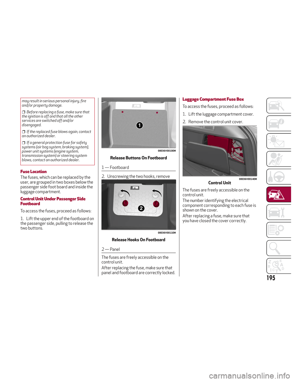
To access the fuses, proceed as follows:
1. Lift the upper end of the footboard on
the passenger side, pulling to release the
two buttons. Release Buttons On Footboard
1 — Footboard
2. Unscrewing the two hooks, remove
the panel pulling downward.
Release Hooks On Footboard
2 — Panel
The fuses are freely accessible on the
control unit.
After replacing the fuse, make sure that
panel and footboard are correctly locked.
Luggage Compartment Fuse Box
To access the fuses, proceed as follows:
1. Lift the luggage compartment cover.
2. Remove the control unit cover.
The fuses are freely accessible on the
control unit.
The number identifying the electrical
component corresponding to each fuse is
shown on the cover.
After replacing a fuse, make sure that
you have closed the cover correctly.
08036V0010EM
08036V0011EM
08036V0014EMControl Unit
195
Page 198 of 276
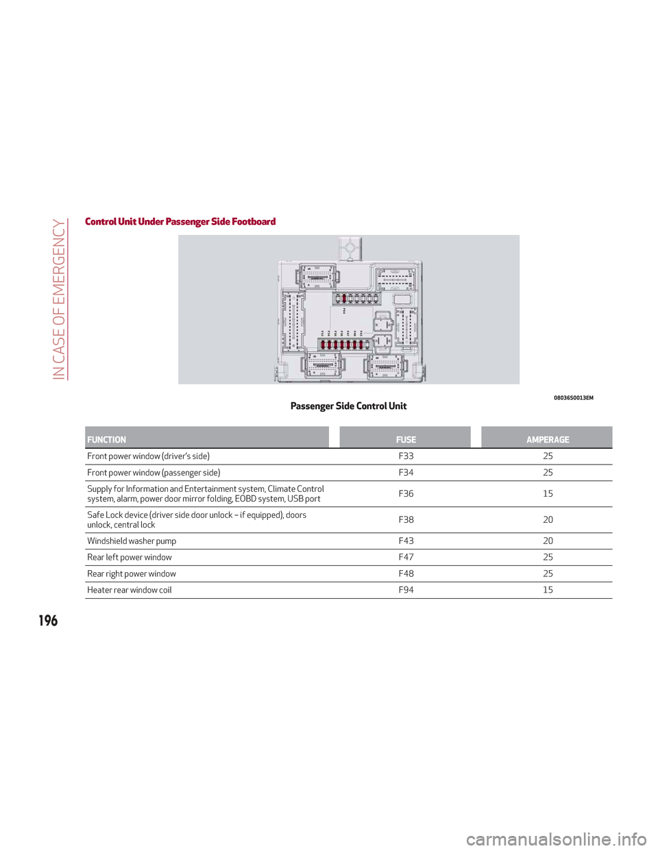
Control Unit Under Passenger Side Footboard
FUNCTIONFUSEAMPERAGE
Front power window (driver’s side) F3325
Front
power window (passenger side) F3425
Supply for Information and Entertainment system, Climate Control
system, alarm, power door mirror folding, EOBD system, USB port F36
15
Safe Lock device (driver side door unlock – if equipped), doors
unlock, central lock F38
20
Windshield washer pump F4320
Rear left power window F4725
Rear right power window F4825
Heater rear window coil F9415
08036S0013EMPassenger Side Control Unit
196
IN CASE OF EMERGENCY
Page 199 of 276
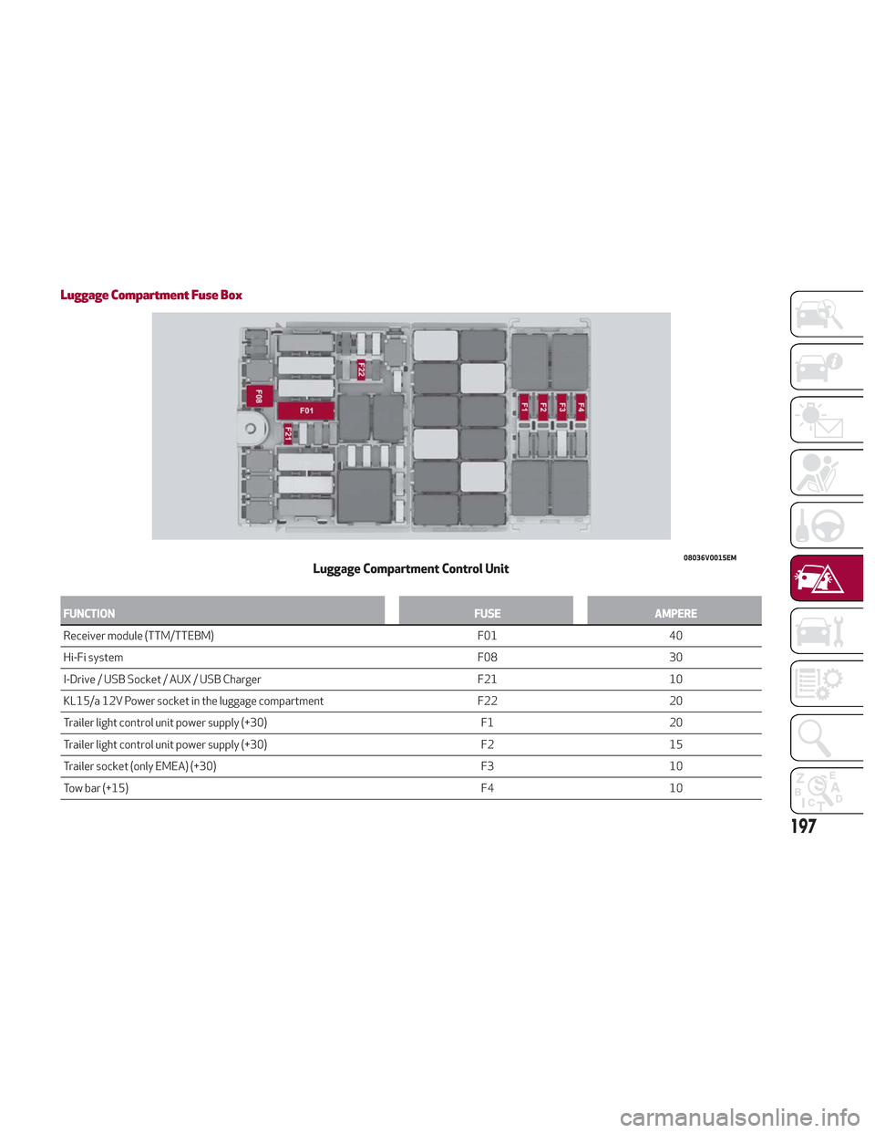
Luggage Compartment Fuse Box
FUNCTIONFUSEAMPERE
Receiver module (TTM/TTEBM) F0140
Hi-Fi
system F0830
I-Drive / USB Socket / AUX / USB Charger F2110
KL15/a 12V Power socket in the luggage compartment F2220
Trailer light control unit power supply (+30) F120
Trailer light control unit power supply (+30) F215
Trailer socket (only EMEA) (+30) F310
Tow bar (+15) F410
08036V0015EMLuggage Compartment Control Unit
197
Page 200 of 276
TIRE SERVICE KIT
Description
If a tire is punctured, you can make a first
emergency repair using the Tire Service
Kit located in the rear storage area under
the load platform.
1. Stop the vehicle in a position where
you can repair the tire safely. You should
be as far as possible from the side of the
road, and in a position that is not
dangerous for oncoming traffic. Turn on
the hazard warning flashers, remove the
safety triangle from the luggage
compartment, and place it at a suitable
distance from the vehicle to make other
drivers aware of your presence.
2. Verify that the valve stem (on the
wheel with the deflated tire) is in a
position that is near to the ground. This
will allow the tire repair kit hoses to reach
the valve stem and keep the tire service
kit flat on the ground.
3. Place the gear selector in PARK (P).
4. Apply the electric park brake and turn
the engine OFF.
To access the Tire Service Kit, open the
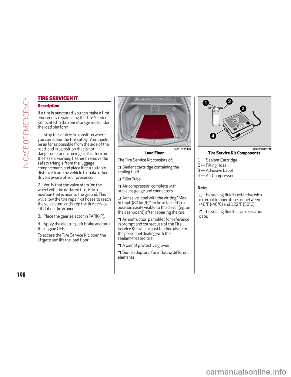
liftgate and lift the load floor.The Tire Service Kit consists of:
Sealant cartridge containing the
sealing fluid
Filler Tube
Air compressor, complete with
pressure gauge and connectors
Adhesive label with the writing "Max.
50 mph (80 km/h)”, to be attached in a
position easily visible to the driver (eg. on
the dashboard) after repairing the tire
An instruction pamphlet for reference
in prompt and correct use of the Tire
Service Kit, which must be then given to
the personnel dealing with the
sealant-treated tire
A pair of protective gloves
Some adaptors, for inflating different
elements Note:
The sealing fluid is effective with
external temperatures of between
-40°F (-40°C) and 122°F (50°C).
The sealing fluid has an expiration
date.
0403132214USLoad Floor08066V0002EMTire Service Kit Components
1 — Sealant Cartridge
2 — Filling Hose
3 — Adhesive Label
4 — Air Compressor
198
IN CASE OF EMERGENCY