gas type Alfa Romeo Stelvio 2018 Owner's Manual
[x] Cancel search | Manufacturer: ALFA ROMEO, Model Year: 2018, Model line: Stelvio, Model: Alfa Romeo Stelvio 2018Pages: 276, PDF Size: 5.79 MB
Page 127 of 276
Driver And Passenger Front Air Bag
Features
The Advanced Front Air Bag system has
multistage driver and front passenger air
bags. This system provides output
appropriate to the severity and type of
collision as determined by the Occupant
Restraint Controller (ORC), which may
receive information from the front
impact sensors (if equipped) or other
system components.
The first stage inflator is triggered
immediately during an impact that
requires air bag deployment. A low
energy output is used in less severe
collisions. A higher energy output is used
for more severe collisions.
This vehicle may be equipped with a
driver and/or front passenger seat belt
buckle switch that detects whether the
driver or front passenger seat belt is
buckled. The seat belt buckle switch may
adjust the inflation rate of the Advanced
Front Air Bags.
This vehicle may be equipped with driver
and/or front passenger seat track
position sensors that may adjust the
inflation rate of the Advanced Front Air
Bags based upon seat position.
Warning!
No objects should be placed over or near
the air bag on the instrument panel or
steering wheel because any such objects
could cause harm if the vehicle is in a
collision severe enough to cause the air bag
to inflate.
Do not put anything on or around the air
bag covers or attempt to open them
manually. You may damage the air bags and
you could be injured because the air bags
may no longer be functional. The protective
covers for the air bag cushions are designed
to open only when the air bags are inflating.
Relying on the air bags alone could lead to
more severe injuries in a collision. The air
bags work with your seat belt to restrain
you properly. In some collisions, air bags
won’t deploy at all. Always wear your seat
belts even though you have air bags.
Front Air Bag Operation
Front Air Bags are designed to provide
additional protection by supplementing
the seat belts. Front air bags are not
expected to reduce the risk of injury in
rear, side, or rollover collisions. The front
air bags will not deploy in all frontal
collisions, including some that may
produce substantial vehicle damage —
for example, some pole collisions, truck
underrides, and angle offset collisions.
On the other hand, depending on the type and location of impact, front air bags may
deploy in crashes with little vehicle
front-end damage but that produce a
severe initial deceleration.
Because air bag sensors measure vehicle
deceleration over time, vehicle speed and
damage by themselves are not good
indicators of whether or not an air bag
should have deployed.
Seat belts are necessary for your
protection in all collisions, and also are
needed to help keep you in position, away
from an inflating air bag.
When the ORC detects a collision
requiring the front air bags, it signals the
inflator units. A large quantity of
non-toxic gas is generated to inflate the
front air bags.
The steering wheel hub trim cover and
the upper passenger side of the
instrument panel separate and fold out of
the way as the air bags inflate to their full
size. The front air bags fully inflate in less
time than it takes to blink your eyes. The
front air bags then quickly deflate while
helping to restrain the driver and front
passenger.
Knee Impact Bolsters
The Knee Impact Bolsters help protect
the knees of the driver and front
passenger, and position the front
occupants for improved interaction with
the front air bags.
125
Page 130 of 276
Relying on the Side Air Bags alone could
lead to more severe injuries in a collision.
The Side Air Bags work with your seat belt
to restrain you properly. In some collisions,
Side Air Bags won’t deploy at all. Always
wear your seat belt even though you have
Side Air Bags.
Note: Air bag covers may not be obvious
in the interior trim, but they will open
during air bag deployment.
Rollover Events
Side Air Bags are designed to activate in
certain rollover events. The ORC
determines whether the deployment of
the Side Air Bags in a particular rollover
event is appropriate, based on the
severity and type of collision. Vehicle
damage by itself is not a good indicator
of whether or not Side Air Bags should
have deployed.
The Side Air Bags will not deploy in all
rollover events. The rollover sensing
system determines if a rollover event
may be in progress and whether
deployment is appropriate. In the event
the vehicle experiences a rollover or near
rollover event, and deployment of the
Side Air Bags is appropriate, the rollover
sensing system will also deploy the seat
belt pretensioners on both sides of the
vehicle.
The SABICs may help reduce the risk of
partial or complete ejection of vehicle
occupants through side windows in
certain rollover or side impact events.
Air Bag System Components
Note: The Occupant Restraint Controller
(ORC) monitors the internal circuits and
interconnecting wiring associated with
electrical Air Bag System Components
listed below:
Occupant Restraint Controller (ORC)
Air Bag Warning Light
Steering Wheel and Column
Instrument Panel
Knee Impact Bolsters
Driver and Front Passenger Air Bags
Seat Belt Buckle Switch
Supplemental Side Air Bags
Supplemental Knee Air Bags
Front and Side Impact Sensors
Seat Belt Pretensioners
Seat Track Position Sensors
If A Deployment Occurs
The front air bags are designed to deflate
immediately after deployment.
Note: Front and/or side air bags will not
deploy in all collisions. This does not
mean something is wrong with the air bag
system. If you do have a collision which deploys
the air bags, any or all of the following
may occur:
The air bag material may sometimes
cause abrasions and/or skin reddening to
the occupants as the air bags deploy and
unfold. The abrasions are similar to
friction rope burns or those you might get
sliding along a carpet or gymnasium floor.
They are not caused by contact with
chemicals. They are not permanent and
normally heal quickly. However, if you
haven’t healed significantly within a few
days, or if you have any blistering, see
your doctor immediately.
As the air bags deflate, you may see
some smoke-like particles. The particles
are a normal by-product of the process
that generates the non-toxic gas used for
air bag inflation. These airborne particles
may irritate the skin, eyes, nose, or
throat. If you have skin or eye irritation,
rinse the area with cool water. For nose
or throat irritation, move to fresh air. If
the irritation continues, see your doctor.
If these particles settle on your clothing,
follow the garment manufacturer’s
instructions for cleaning.
Do not drive your vehicle after the air
bags have deployed. If you are involved in
another collision, the air bags will not be
in place to protect you.
128
SAFETY
Page 163 of 276
ALFA ACTIVE SUSPENSION
(AAS)
The vehicle's electronic suspension
management system is aimed at
optimizing the vehicle's performance.
The system continuously monitors the
damping of the suspensions through the
actuator installed on each shock
absorber. This way, the calibration of the
shock absorbers can be adjusted to the
conditions of the road surface and to the
dynamic conditions of the vehicle,
improving its comfort and road holding.
The driver can choose, even while driving,
(only in "Dynamic” mode), between two
types of suspension calibration: a more
sporty or a more comfortable one.
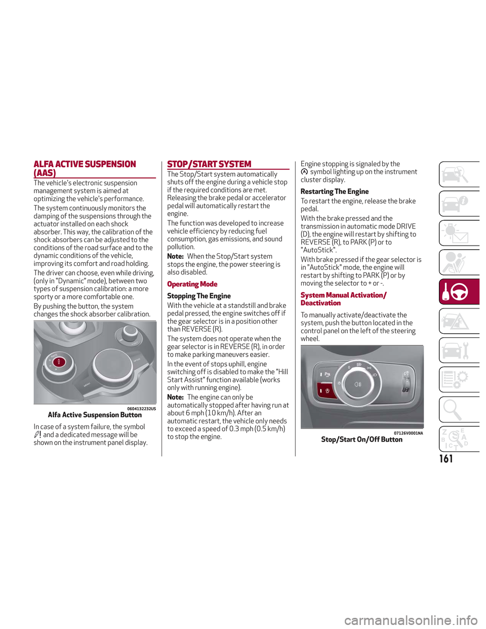
By pushing the button, the system
changes the shock absorber calibration.
In case of a system failure, the symbol
and a dedicated message will be
shown on the instrument panel display.
STOP/START SYSTEM
The Stop/Start system automatically
shuts off the engine during a vehicle stop
if the required conditions are met.
Releasing the brake pedal or accelerator
pedal will automatically restart the
engine.
The function was developed to increase
vehicle efficiency by reducing fuel
consumption, gas emissions, and sound
pollution.
Note:When the Stop/Start system
stops the engine, the power steering is
also disabled.
Operating Mode
Stopping The Engine
With the vehicle at a standstill and brake
pedal pressed, the engine switches off if
the gear selector is in a position other
than REVERSE (R).
The system does not operate when the
gear selector is in REVERSE (R), in order
to make parking maneuvers easier.
In the event of stops uphill, engine
switching off is disabled to make the "Hill
Start Assist" function available (works
only with running engine).
Note: The engine can only be
automatically stopped after having run at
about 6 mph (10 km/h). After an
automatic restart, the vehicle only needs
to exceed a speed of 0.3 mph (0.5 km/h)
to stop the engine. Engine stopping is signaled by the
symbol lighting up on the instrument
cluster display.
Restarting The Engine
To restart the engine, release the brake
pedal.
With the brake pressed and the
transmission in automatic mode DRIVE
(D), the engine will restart by shifting to
REVERSE (R), to PARK (P) or to
"AutoStick".
With brake pressed if the gear selector is
in "AutoStick" mode, the engine will
restart by shifting to PARK (P) or by
moving the selector to + or -.
System Manual Activation/
Deactivation
To manually activate/deactivate the
system, push the button located in the
control panel on the left of the steering
wheel.
0604132232USAlfa Active Suspension Button
07126V0001NAStop/Start On/Off Button
161
Page 182 of 276
The table below shows the approximate
distances for each area:
AreaDistance From The
Rear Of The Vehicle
Red 0–11.8
inches
(0–30 cm)
Yellow 11.8 inches to 3.3 feet
(30cm–1m)
Green 3.3feetormore(1m
or more)
Messages On The Display
If the liftgate is opened, the camera will
not detect any obstacle behind the
vehicle. The display will show a dedicated
warning message.
Make sure the liftgate is closed by
pushing next to the lock until it clicks.
Important Notes
Ice, snow or mud on the surface of the
camera may reduce its sensitivity. It is
important to keep the camera surface
clean, and free from debris.
When parking, be aware of obstacles
that may be above or below the camera
range.
REFUELING THE VEHICLE
Refueling The Vehicle
Before refueling, make sure that the fuel
type is correct.
Also, stop the engine before refueling.
Note: An inefficient catalytic converter
leads to harmful exhaust emissions, thus
contributing to air pollution.
Caution!
Never introduce leaded fuel to the tank,
even in small amounts in an emergency, as
this would damage the catalytic converter
beyond repair.
Refueling Capacity
To ensure that you fill the tank
completely, top off twice after the first
click of the fuel nozzle.
Further top-off could cause faults in the
fuel feeding system.
Refueling Procedure
The fuel filler door is unlocked when the
central door locking system is unlocked.
It is automatically locked when the
central locking system is applied. Opening The Fuel Filler Door
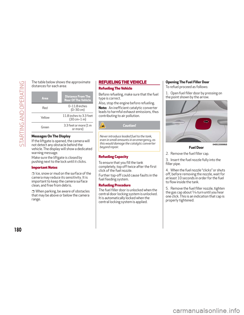
To refuel proceed as follows:
1. Open fuel filler door by pressing on
the point shown by the arrow.
2. Remove the fuel filler cap.
3. Insert the fuel nozzle fully into the
filler pipe.
4. When the fuel nozzle “clicks” or shuts
off, before removing the nozzle, wait for
at least 10 seconds in order for the fuel
to flow inside the tank.
5. Remove the fuel filler nozzle, tighten
the gas cap about ¼ turn until you hear
one click. This is an indication that cap is
properly tightened.
0405133008USFuel Door
180
STARTING AND OPERATING
Page 183 of 276
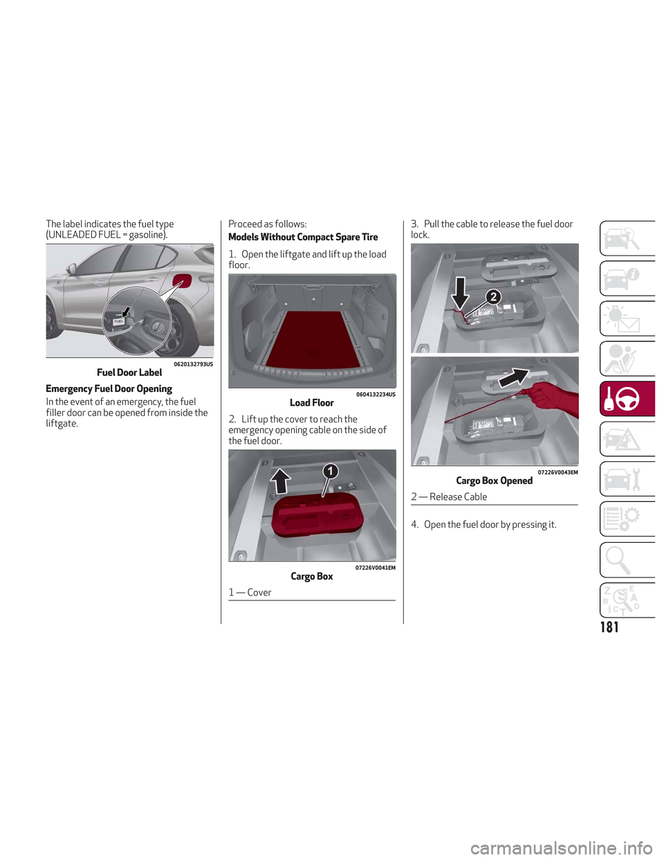
The label indicates the fuel type
(UNLEADED FUEL = gasoline).
Emergency Fuel Door Opening
In the event of an emergency, the fuel
filler door can be opened from inside the
liftgate.Proceed as follows:
Models Without Compact Spare Tire
1. Open the liftgate and lift up the load
floor.
2. Lift up the cover to reach the
emergency opening cable on the side of
the fuel door.3. Pull the cable to release the fuel door
lock.
4. Open the fuel door by pressing it.
0620132793USFuel Door Label
0604132234USLoad Floor
07226V0041EMCargo Box
1 — Cover
07226V0043EMCargo Box Opened
2 — Release Cable
181
Page 191 of 276
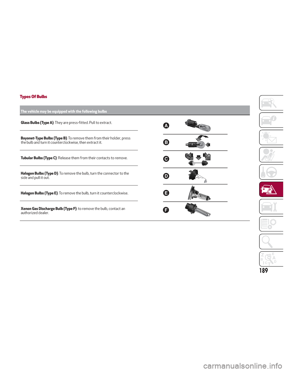
Types Of Bulbs
The vehicle may be equipped with the following bulbs
Glass Bulbs (Type A):
They are press-fitted. Pull to extract.
Bayonet-Type Bulbs (Type B) : To remove them from their holder, press
the bulb and turn it counterclockwise, then extract it.
Tubular Bulbs (Type C) : Release them from their contacts to remove.
Halogen Bulbs (Type D) : To remove the bulb, turn the connector to the
side and pull it out.
Halogen Bulbs (Type E) : To remove the bulb, turn it counterclockwise.
Xenon Gas Discharge Bulb (Type F) : to remove the bulb, contact an
authorized dealer.
189
Page 192 of 276
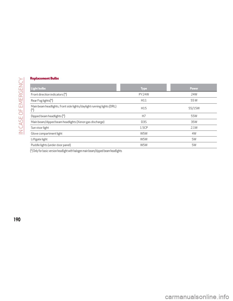
Replacement Bulbs
Light bulbsTypePower
Front direction indicators
(*)PY24W 24W
Rear Fog lights
(*)H11 55 W
Main beam headlights, front side lights/daylight running lights (DRL)
(*)H15 55/15W
Dipped beam headlights
(*)H7 55W
Main beam/dipped beam headlights (Xenon gas discharge) D3S35W
Sun visor light 1.5CP2.1W
Glove compartment light W5W4W
Liftgate light W5W5W
Puddle lights (under door panel) W5W5W
(*) Only for basic version headlight with halogen main beam/dipped beam headlights
190
IN CASE OF EMERGENCY
Page 271 of 276
Fuse Boxes............... .195
Fuses (Replacement) ..........193
Garage Door Opener (HomeLink) ....63
Gasoline, Clean Air ............255
Gasoline, Reformulated .........255
General Information ........109,114
Glove Compartment ............63
Glove Compartment Light ........42
Glove Compartment Light (Bulb Replacement) .............192
GVWR .................. .182
Hazard Warning Flasher .........188
Head Restraints ..............34
Head Rests .................34
Headlights Switch ............... .38,40
Headlights (Cleaning) ..........243
Heated Mirrors ...............38
Heater, Engine Block ...........149
High Beam Headlights ...........40
Automatic High Beam Headlights .......................41
Hill Start Assist (HSA) System .....106
Hood .....................57
Hood Release ................57
Identification Data ............246
Ignition ....................19 Installing Electrical/Electronic
Devices ...................4
Instrument Cluster .............70
Instrument Cluster Display Instrument Cluster Display ......71
Reconfigurable Instrument
Cluster Display .............72
Instrument Panel Features Instrument Panel Features ......70
Interior Ambient Lighting .........43
Interior Lights ................41
Interiors (Cleaning) ............244
Internal Equipment ............63
Jack Operation ............. .225
Jump Starting ............201,202
Key Fob Remote Keyless Entry .........16
Key Fob Battery Service (Remote Keyless Entry) ..............17
Key, Replacement .............18
Keyless Enter-N-Go Passive Entry ..............24
K
eyless Entry System/Immobilizer System ..................20
Lane Change ................41
Lane Change And Turn Signals ......41
Lane Departure Warning System . . .176
LaneSense ................ .176Lap/Shoulder Belts
...........118
Latches .................. .143
Leaks, Fluid ............... .143
Life Of Tires ............... .236
Liftgate ...................58
Lifting The Vehicle ............225
Light Bulbs ................ .143
Types Of Bulbs ............189
Light Switch .................38
Lights ................... .143
AirBag ..............123,142
Automatic Headlights .........39
Courtesy/Reading .........41,43
Daytime Running ............39
Exterior ............... .143
Hazard Warning Flasher .......188
Headlight Switch ..........38,40
Headlights .............38,40
High Beam ................40
Instrument Cluster ........38,40
Intensity Control ............44
Interior ..................43
Map Reading ..............41
Park ...................39
Reading .................41
Turn Signal ............41,143
Loading Vehicle ..............182
Tires .................. .230