radio Alfa Romeo Stelvio 2018 Owner's Manual
[x] Cancel search | Manufacturer: ALFA ROMEO, Model Year: 2018, Model line: Stelvio, Model: Alfa Romeo Stelvio 2018Pages: 276, PDF Size: 5.79 MB
Page 6 of 276
VEHICLE CHANGES / ALTERATIONS
Accessories Purchased By The Owner
Warning!
Any change or alteration of the vehicle might seriously affect its safety and road handling, thus causing accidents, in which the occupants could
even be fatally injured.
If you decide to install electrical accessories that require a permanent electrical supply (e.g. radio, satellite anti-theft system, etc.) or
accessories that in any case drain the electrical supply after purchasing the vehicle, contact your authorized dealer. Dealer personnel
will check whether the vehicles's electrical system is able to withstand the load required or whether it needs to be integrated with a
more powerful battery.
Note:Use caution when adding additional spoilers, alloy wheel rims, or non-standard wheel hubs: they could reduce the ventilation
of the brakes and affect efficiency under sharp and repeated braking, or on long descents. Make sure that nothing obstructs the
pedal (mats, etc.).
FCA US LLC shall not be liable for damage caused by the installation of accessories either not supplied or recommended by FCA US
LLC and/or not installed in compliance with the provided instructions.
Installing Electrical/Electronic Devices
FCA US LLC authorizes the installation of transceivers provided that installation is carried out at a specialized center, in compliance
with manufacturer's specifications.
Note: Local authorities may not allow the vehicle on the road if devices that modify the features of the vehicle have been installed.
This also may void the warranty in relation to faults caused by the change either directly or indirectly related to it.
FCA US LLC shall not be liable for damage caused by the installation of accessories either not supplied or recommended by FCA US
LLC and/or not installed in compliance with the provided instructions.
Page 7 of 276
Radio Transmitters And Mobile Phones
Radio transmitter equipment (vehicle mobile phones, CB radios, amateur radio etc.) cannot be used inside the vehicle unless a
separate antenna is mounted externally.
Transmission and reception of these devices may be affected by the shielding effect of the vehicle body. As far as the use of
approved mobile phones is concerned, follow the usage instructions provided by the mobile phone Manufacturer.
Caution!
The use of these devices inside the passenger compartment (without an external antenna) may cause the electrical systems to malfunction.
This could compromise the safety of the vehicle in addition to constituting a potential hazard for passengers' health.
If mobile phones/laptops/smartphones/tablets are inside the vehicle and/or close to the electronic key, a reduced performance of the Passive
Entry/Keyless Start system may occur may occur.
Page 20 of 276
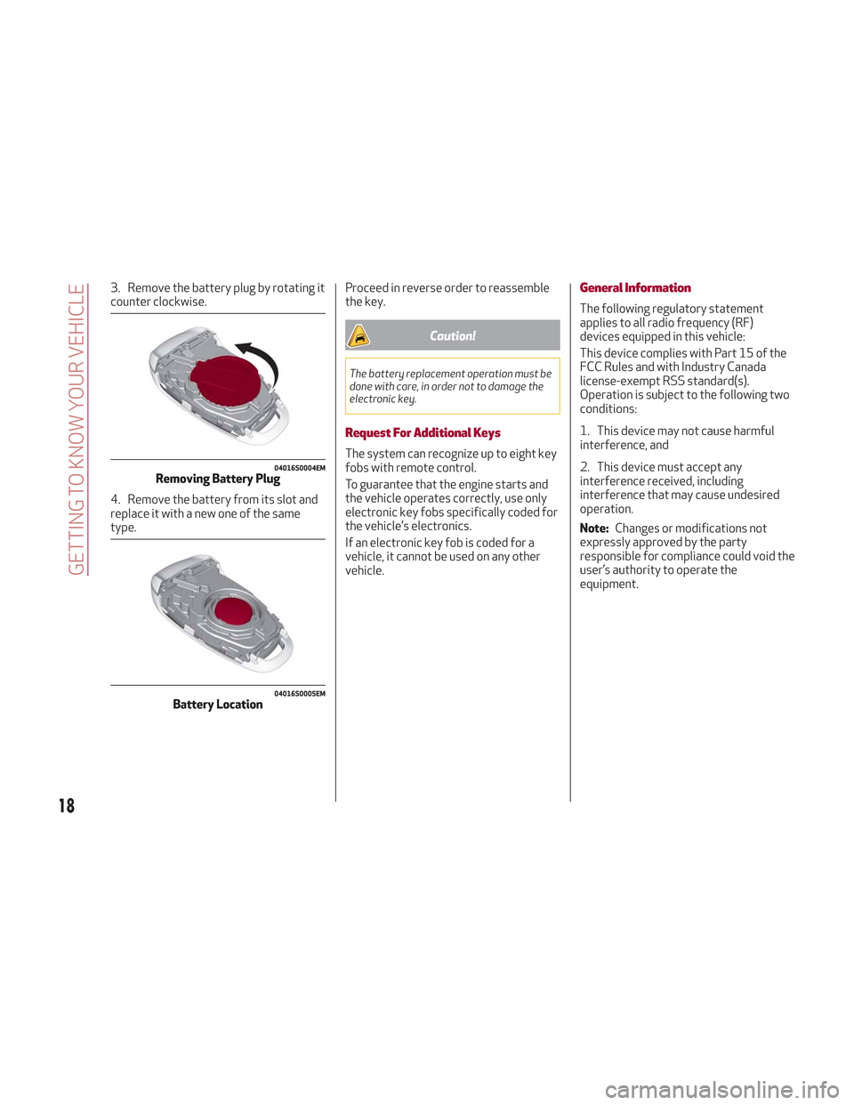
3. Remove the battery plug by rotating it
counter clockwise.
4. Remove the battery from its slot and
replace it with a new one of the same
type.Proceed in reverse order to reassemble
the key.
Caution!
The battery replacement operation must be
done with care, in order not to damage the
electronic key.
Request For Additional Keys
The system can recognize up to eight key
fobs with remote control.
To guarantee that the engine starts and
the vehicle operates correctly, use only
electronic key fobs specifically coded for
the vehicle’s electronics.
If an electronic key fob is coded for a
vehicle, it cannot be used on any other
vehicle.
General Information
The following regulatory statement
applies to all radio frequency (RF)
devices equipped in this vehicle:
This device complies with Part 15 of the
FCC Rules and with Industry Canada
license-exempt RSS standard(s).
Operation is subject to the following two
conditions:
1. This device may not cause harmful
interference, and
2. This device must accept any
interference received, including
interference that may cause undesired
operation.
Note:
Changes or modifications not
expressly approved by the party
responsible for compliance could void the
user’s authority to operate the
equipment.
04016S0004EMRemoving Battery Plug
04016S0005EMBattery Location
18
GETTING TO KNOW YOUR VEHICLE
Page 22 of 276
Starting With A Discharged Key Fob
Battery
If the key fob battery is discharged,
proceed as follows to start the vehicle:
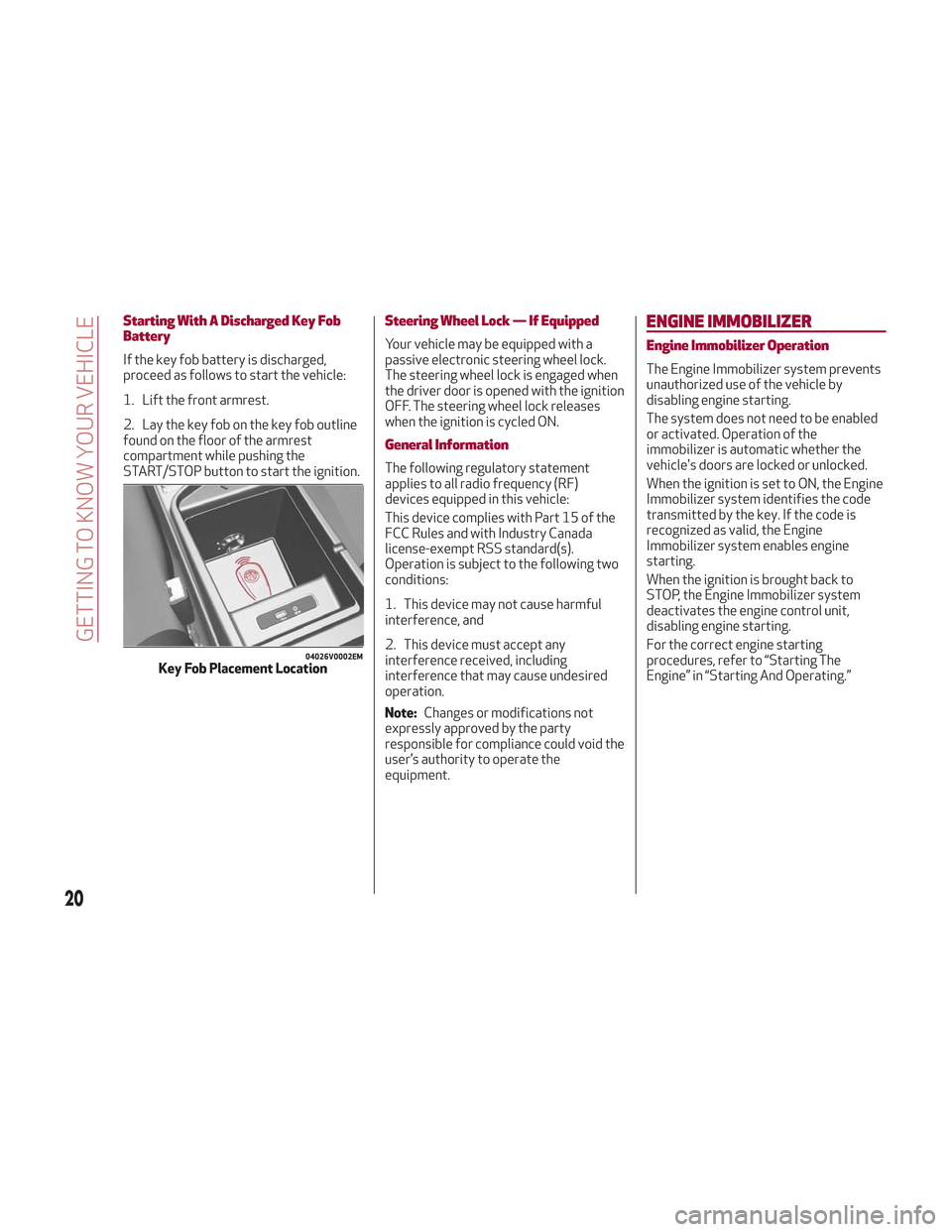
1. Lift the front armrest.
2. Lay the key fob on the key fob outline
found on the floor of the armrest
compartment while pushing the
START/STOP button to start the ignition.
Steering Wheel Lock — If Equipped
Your vehicle may be equipped with a
passive electronic steering wheel lock.
The steering wheel lock is engaged when
the driver door is opened with the ignition
OFF. The steering wheel lock releases
when the ignition is cycled ON.
General Information
The following regulatory statement
applies to all radio frequency (RF)
devices equipped in this vehicle:
This device complies with Part 15 of the
FCC Rules and with Industry Canada
license-exempt RSS standard(s).
Operation is subject to the following two
conditions:
1. This device may not cause harmful
interference, and
2. This device must accept any
interference received, including
interference that may cause undesired
operation.
Note:Changes or modifications not
expressly approved by the party
responsible for compliance could void the
user’s authority to operate the
equipment.
ENGINE IMMOBILIZER
Engine Immobilizer Operation
The Engine Immobilizer system prevents
unauthorized use of the vehicle by
disabling engine starting.
The system does not need to be enabled
or activated. Operation of the
immobilizer is automatic whether the
vehicle's doors are locked or unlocked.
When the ignition is set to ON, the Engine
Immobilizer system identifies the code
transmitted by the key. If the code is
recognized as valid, the Engine
Immobilizer system enables engine
starting.
When the ignition is brought back to
STOP, the Engine Immobilizer system
deactivates the engine control unit,
disabling engine starting.
For the correct engine starting
procedures, refer to “Starting The
Engine” in “Starting And Operating.”
04026V0002EMKey Fob Placement Location
20
GETTING TO KNOW YOUR VEHICLE
Page 29 of 276
System Activation/Deactivation
The Passive Entry system can be
activated or deactivated using the
Information and Entertainment System.
General Information
The following regulatory statement
applies to all radio frequency (RF)
devices equipped in this vehicle:
This device complies with Part 15 of the
FCC Rules and with Industry Canada
license-exempt RSS standard(s).
Operation is subject to the following two
conditions:
1. This device may not cause harmful
interference, and
2. This device must accept any
interference received, including
interference that may cause undesired
operation.
Note:Changes or modifications not
expressly approved by the party
responsible for compliance could void the
user’s authority to operate the
equipment.
Power Lock
The power lock is a safety device that
prevents the operation of the interior
door handles and the door lock and
unlock buttons. The power lock also
prevent opening of the doors from inside
the passenger compartment.
It is recommended to lock the vehicle
doors each time the vehicle is parked.
Activating The Power Lock
The power lock is enabled on all the doors
by quickly pushing the lock button on the
key fob twice.
The turn signals will flash to let you know
that the power lock is active.
If one or more of the doors are not closed
correctly, the power lock will not activate,
preventing a person from getting stuck
inside the passenger compartment by
entering the vehicle, and then closing, the
open door.
Deactivating The Power Lock
The power lock disengages
automatically:
When the doors are unlocked, pushing
the unlock button on the key fob.
When the keyless ignition is placed in
the ON position.
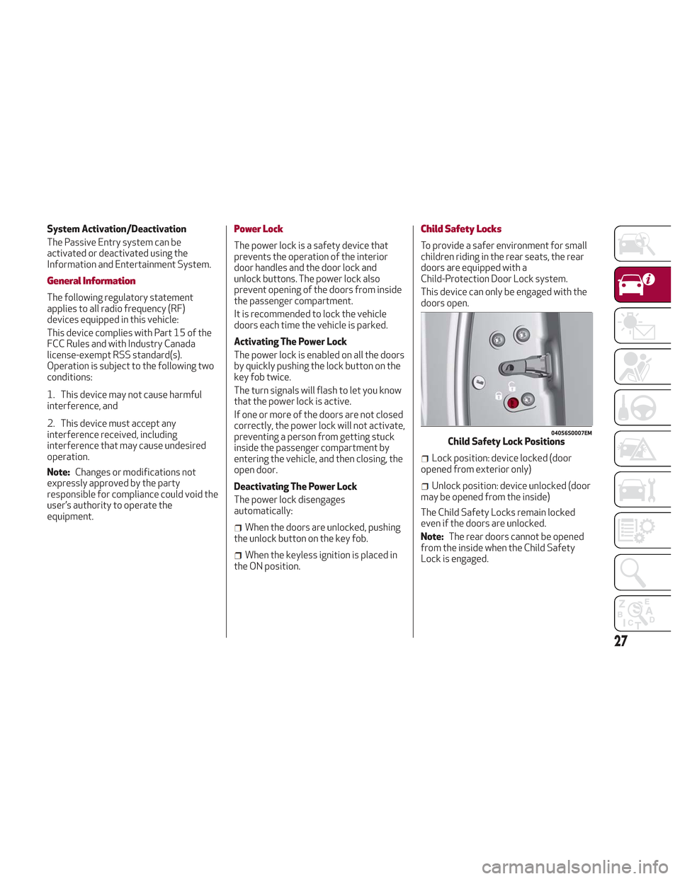
Child Safety Locks
To provide a safer environment for small
children riding in the rear seats, the rear
doors are equipped with a
Child-Protection Door Lock system.
This device can only be engaged with the
doors open.
Lock position: device locked (door
opened from exterior only)
Unlock position: device unlocked (door
may be opened from the inside)
The Child Safety Locks remain locked
even if the doors are unlocked.
Note: The rear doors cannot be opened
from the inside when the Child Safety
Lock is engaged.
04056S0007EMChild Safety Lock Positions
27
Page 52 of 276
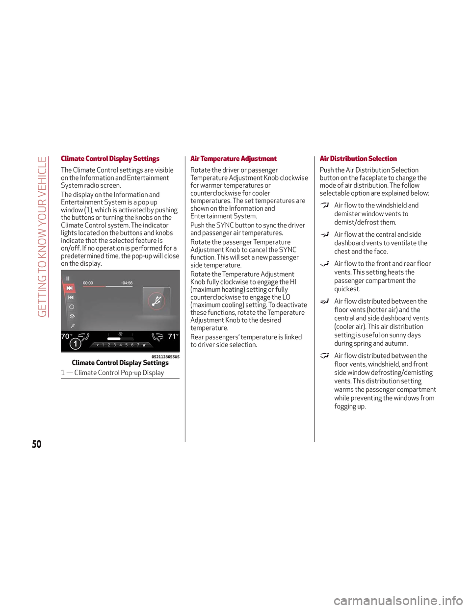
Climate Control Display Settings
The Climate Control settings are visible
on the Information and Entertainment
System radio screen.
The display on the Information and
Entertainment System is a pop up
window (1), which is activated by pushing
the buttons or turning the knobs on the
Climate Control system. The indicator
lights located on the buttons and knobs
indicate that the selected feature is
on/off. If no operation is performed for a
predetermined time, the pop-up will close
on the display.
Air Temperature Adjustment
Rotate the driver or passenger
Temperature Adjustment Knob clockwise
for warmer temperatures or
counterclockwise for cooler
temperatures. The set temperatures are
shown on the Information and
Entertainment System.
Push the SYNC button to sync the driver
and passenger air temperatures.
Rotate the passenger Temperature
Adjustment Knob to cancel the SYNC
function. This will set a new passenger
side temperature.
Rotate the Temperature Adjustment
Knob fully clockwise to engage the HI
(maximum heating) setting or fully
counterclockwise to engage the LO
(maximum cooling) setting. To deactivate
these functions, rotate the Temperature
Adjustment Knob to the desired
temperature.
Rear passengers’ temperature is linked
to driver side selection.
Air Distribution Selection
Push the Air Distribution Selection
button on the faceplate to change the
mode of air distribution. The follow
selectable option are explained below:
Air flow to the windshield and
demister window vents to
demist/defrost them.
Air flow at the central and side
dashboard vents to ventilate the
chest and the face.
Air flow to the front and rear floor
vents. This setting heats the
passenger compartment the
quickest.
Air flow distributed between the
floor vents (hotter air) and the
central and side dashboard vents
(cooler air). This air distribution
setting is useful on sunny days
during spring and autumn.
Air flow distributed between the
floor vents, windshield, and front
side window defrosting/demisting
vents. This distribution setting
warms the passenger compartment
while preventing the windows from
fogging up.0521128655USClimate Control Display Settings
1 — Climate Control Pop-up Display
50
GETTING TO KNOW YOUR VEHICLE
Page 68 of 276
2. When the HomeLink indicator begins
to flash slowly, move the portable remote
control 1 to 3 inches from the system
(keeping the programmable button
pressed down).
If the indicator does not begin to flash
quickly, change the distance between the
HomeLink and the portable remote
control and try the procedure again.
The HomeLink indicator flashes, first
slowly and then quickly. When the
indicator starts to flash quickly, release
both buttons on the remote control.
The system previously programmed to
HomeLink has now been deleted and the
new system is ready to use. This does not
affect the other two HomeLink buttons in
any way.
Deleting Programmed Keys
It is recommended to delete HomeLink
programming before selling the vehicle.
All three keys are deleted
simultaneously.
Proceed as follows:
1. Push and hold the outer buttons
(1 and 3). After about ten seconds, the
indicator will start to flash.
2. Release both keys. Technical Information For After Sales
Service
If you are unable to set up HomeLink
successfully after following the above
instructions, contact After Sales Service
(HomeLink free hotline number
1-800-355-3515 ) with the following
information:
Vehicle make and model, including
manufacturing year and country of
purchase;
Make, model, age and frequency of use
of the original portable remote control (if
known).
General Information
The following regulatory statement
applies to all Radio Frequency (RF)
devices equipped in this vehicle:
This device complies with Part 15 of the
FCC Rules and with Industry Canada
license-exempt RSS standard(s).
Operation is subject to the following two
conditions:
1. This device may not cause harmful
interference, and
2. This device must accept any
interference received, including
interference that may cause undesired
operation.
Note: Changes or modifications not
expressly approved by the party
responsible for compliance could void the
user’s authority to operate the
equipment.
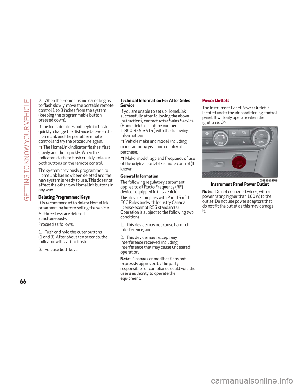
Power Outlets
The Instrument Panel Power Outlet is
located under the air conditioning control
panel. It will only operate when the
ignition is ON.
Note: Do not connect devices, with a
power rating higher than 180 W, to the
outlet. Do not use power adaptors that
do not fit the outlet as this may damage
it.
0313132162USInstrument Panel Power Outlet
66
GETTING TO KNOW YOUR VEHICLE
Page 106 of 276
ACTIVE SAFETY SYSTEMS
The vehicle may be equipped with the
following active safety devices:
Anti-Lock Braking (ABS) System
Drive Train Control (DTC) System
Electronic Stability Control (ESC)
System
Traction Control System (TCS)
Panic Brake Assist (PBA) System
Hill Start Assist (HSA) System
Dynamic Steering Torque (DST)
System
Active Torque Vectoring (ATV) System
For system operation, see the following
pages.
Anti-Lock Braking (ABS) System
An integral part of the braking system,
the ABS prevents one or more wheels
from locking and slipping in all road
surface conditions, regardless of the
intensity of the braking action. The
system ensures that the vehicle can be
controlled even during emergency
braking, allowing the driver to optimize
stopping distances.
The system intervenes during braking
when the wheels are about to lock,
typically in emergency braking or
low-grip conditions where locking may be
more frequent. The system also improves control and
stability of the vehicle when braking on a
surface where the grip of the left and
right wheels varies, such as in a corner.
The Electronic Braking Force Distribution
(EBD) system works with the ABS,
allowing the brake force to be distributed
between the front and rear wheels.
System Intervention
The ABS equipped on this vehicle is
provided with the "Brake-By-Wire"
(Integrated Brake System - IBS) function.
With this system, the command given by
pressing the brake pedal is not
transmitted hydraulically, but electrically.
Therefore, the light pulsation that is felt
on the pedal with the traditional system
is no longer noticeable.Warning!
The ABS contains sophisticated
electronic equipment that may be
susceptible to interference caused by
improperly installed or high output radio
transmitting equipment. This interference
can cause possible loss of anti-lock braking
capability. Installation of such equipment
should be performed by qualified
professionals.
Pumping of the Anti-Lock Brakes will
diminish their effectiveness and may lead to a
collision. Pumping makes the stopping distance
longer. Just press firmly on your brake pedal
when you need to slow down or stop.
The ABS cannot prevent the natural laws
of physics from acting on the vehicle, nor
can it increase braking or steering efficiency
beyond that afforded by the condition of the
vehicle brakes and tires or the traction
afforded.
The ABS cannot prevent collisions,
including those resulting from excessive
speed in turns, following another vehicle too
closely, or hydroplaning.
The capabilities of an ABS equipped
vehicle must never be exploited in a reckless
or dangerous manner that could jeopardize
the user’s safety or the safety of others.
Drive Train Control (DTC) System
Some models of this vehicle are equipped
with an All-Wheel Drive system (AWD),
which offers an optimal drive for
countless driving conditions and road
surfaces. The system reduces tire
slipping to a minimum, automatically
redistributing the torque to the front and
rear wheels as needed.
To maximize fuel savings, the vehicle with
AWD automatically passes to rear-wheel
drive (RWD) when the road and
environmental conditions are such that
they wouldn't cause the tires to slip.
When the road and environmental
conditions require better traction, the
vehicle automatically switches to AWD
mode.
104
SAFETY
Page 111 of 276
Overtaking Vehicles
If another vehicle is overtaken slowly,
with a difference in speed of less than
approximately 15 mph (25 km/h) and the
vehicle stays in the blind spot for
approximately 1.5 seconds, the warning
light on the door mirror of the
corresponding side illuminates.
If the difference in speed between the
two vehicles is greater than
approximately 15 mph (25 km/h), the
warning light does not illuminate.
Rear Cross Path Detection (RCP)
System
This system assists the driver during
reverse maneuvers in the case of reduced
visibility.
The RCP system monitors the rear
detection areas on both sides of the
vehicle to detect objects moving toward
the sides of the vehicle, with a minimum
speed between approximately 1 mph
(1 km/h) and 2 mph (3 km/h) and objects
moving at a maximum speed of 21 mph
(35 km/h), in areas such as parking lots.
The system activation is signaled to the
driver by an audible warning.
Note:If the sensors are covered by
objects or vehicles, the system may not
work as intended.
Warning!
Rear Cross Path Detection (RCP) is not a
back up aid system. It is intended to be used
to help a driver detect an oncoming vehicle in
a parking lot situation. Drivers must be
careful when backing up, even when using
RCP. Always check carefully behind your
vehicle, look behind you, and be sure to check
for pedestrians, animals, other vehicles,
obstructions, and blind spots before backing
up. Failure to do so can result in serious
injury or death.
Operating Mode
The system may be activated/
deactivated via the Information and
Entertainment System. To access the
function, select the following items on
the main menu in sequence:
1. “Settings.”
2. “Safety.”
3. “Blind Spot Alert.”
"Blind Spot Alert", "Visual" Mode
When the system is enabled, the warning
light within the door mirror on the side of
the detected object illuminates.
The visual warning on the mirror will blink
if the driver activates the turn signals,
thus indicating the intention to change
lane. The warning light will be constant if the
driver stays in the same lane.
"Blind Spot Alert" Function
Deactivation
When the system is deactivated ("Blind
Spot Alert" mode off), the BSM or RCP
systems will not emit neither an acoustic
nor visual warning.
The BSM system will store the operating
mode that was active when the engine
was stopped. Each time the engine is
started, the operating mode last set will
be recalled and used.
General Information
This vehicle has systems that operate on
radio frequency that comply with Part
15 of the Federal Communications
Commission (FCC) rules and with
Industry Canada Standards RSS-
GEN/210/220/310.
Operation is subject to the following two
conditions:
1. The device may not cause harmful
interference.
2. The device must accept any
interference received, including
interference that may cause undesired
operation of the device.
Changes or modifications to any of these
systems by other than an authorized
service facility could void authorization
to use this equipment.
109
Page 116 of 276
The system has been designed for road
use only. If the vehicle is driven on a track,
the system must be deactivated to avoid
unnecessary warnings. Automatic
deactivation is signaled by the dedicated
warning light/symbol switching on in the
instrument panel (refer to the instructions in
the "Warning Lights And Messages On The
Instrument Panel" in "Getting To Know Your
Instrument Panel" for further information).
General Information
This vehicle has systems that operate on
radio frequency that comply with Part
15 of the Federal Communications
Commission (FCC) rules and with
Industry Canada Standards RSS-
GEN/210/220/310.
Operation is subject to the following two
conditions:
1. The device may not cause harmful
interference.
2. The device must accept any
interference received, including
interference that may cause undesired
operation of the device.
Changes or modifications to any of these
systems by other than an authorized
service facility could void authorization
to use this equipment.
Tire Pressure Monitoring System
(TPMS)
The vehicle is equipped with a Tire
Pressure Monitoring System (TPMS) that
sends the inflation pressure information
of each tire to the control unit, and will
signal the driver in the event of
insufficient tire pressure.
Tire pressure will vary with temperature
by approximately 1 psi (7 kPa) for every
12°F (6.5°C). This means that when the
outside temperature decreases, the tire
pressure will also decrease. Tire pressure
should always be set based on cold
inflation tire pressure. This is defined as
the tire pressure after the vehicle has not
been driven for at least three hours, or
driven less than 1 mile (1.6 km) after a
three hour period. The cold tire inflation
pressure must not exceed the maximum
inflation pressure molded into the tire
sidewall. Refer to “Tires” in “Servicing
And Maintenance” for information on
how to properly inflate the vehicle’s tires.
The tire pressure will also increase as the
vehicle is driven. This is normal, and there
should be no adjustment for this
increased pressure.
The TPMS will signal the driver if
pressure falls below the warning limit for
any reason, including the effects of low
temperature and normal loss of pressure
from the tire.
The TPMS will stop indicating insufficient
tire pressure when pressure is equal to or
greater than the prescribed cold inflation level. Therefore, if insufficient tire
pressure is indicated by the (
) warning
light displaying in the instrument cluster,
increase the inflation pressure up to the
prescribed cold inflation value.
The system will automatically update,
and the “Tire Pressure Monitoring
Warning Light” will turn off once the
system receives the updated tire
pressures. The vehicle may need to be
driven for up to 20 minutes above
15 mph (24 km/h) in order for the TPMS
to receive this information.
Operating Example
For example, your vehicle may have a
recommended cold (parked for more than
three hours) placard pressure of 33 psi
(227 kPa). If the ambient temperature is
68°F (20°C), and the measured tire
pressure is 28 psi (193 kPa), a
temperature drop to 20°F (-7°C) will
decrease the tire pressure to
approximately 24 psi (165 kPa). This tire
pressure is low enough to turn on the
“Tire Pressure Monitoring Warning Light.”
Driving the vehicle may cause the tire
pressure to rise to approximately 28 psi
(193 kPa), but the “Tire Pressure
Monitoring Warning Light” will still be on.
In this situation, the “Tire Pressure
Monitoring Warning Light” will turn off
only after the tires are inflated to the
vehicle’s recommended cold placard
pressure value.
114
SAFETY