display ALFA ROMEO STELVIO 2021 Repair Manual
[x] Cancel search | Manufacturer: ALFA ROMEO, Model Year: 2021, Model line: STELVIO, Model: ALFA ROMEO STELVIO 2021Pages: 280, PDF Size: 10.02 MB
Page 133 of 280
131
(Continued)
Changing The System Strength
The system’s strength can be set through the
radio system in the “Driver Assistance” menu.
Select “Lane Keep Assist - Settings” and then
“Strength”. Strength “Low” or “High” can be
selected.
Limited Operation Warning
If a message appears on the display, a condi-
tion limiting the LKA system operation may
have occurred. This could be an obstruction of
the camera view, or a fault in the system.
If an obstruction is detected, clean the area of
the windshield by the interior rearview mirror.
Although the vehicle can still be driven in
normal conditions, the system may not func -
tion properly.
When the conditions limiting the system are
corrected, it will go back to normal operation.
Should a fault persist, contact an authorized
dealer.
System Failure Signaling
If the system turns off and appears on the
display, it means that there is a system fault.
In this case, it is still possible to drive the
vehicle, but you are advised to contact an
authorized dealer as soon as possible. CAUTION!
Projecting loads on the roof of the vehicle
may interfere with the correct operation of
the camera. Before starting, make sure
the load is correctly positioned, in order
not to cover the camera operating range.
If the windshield must be replaced due to
scratches, chips or breakage, contact an
authorized dealer. Do not replace the
windshield on your own; there is risk of
malfunction. It is advisable to replace the
windshield if it is damaged in the area of
the camera.
Do not tamper with or operate on the
camera. Do not close the openings in the
aesthetic cover located under the interior
rearview mirror. In the event of a failure of
the camera, contact an authorized dealer
immediately.
Do not cover the operating range of the
camera with stickers or other objects. Also
pay attention to other objects on the hood
(e.g. a layer of snow) and make sure they
do not interfere with the camera.
The camera may have limited or absent
operation due to weather conditions such
as: heavy rain, hail, thick fog, heavy snow,
formation of ice layers on the windshield.
Camera operation may also be compro -
mised by the presence of dust, condensa -
tion, dirt or ice on the windshield, traffic
conditions (e.g. vehicles that are driving
not aligned with yours, vehicle driving in a
transverse or opposite way on the same
lane, bend with a small radius of curva -
ture), or road surface conditions and
driving conditions (e.g. off-road driving).
Make sure the windshield is always clean.
Use specific detergents and clean cloths
to avoid scratching the windshield. The
camera operation may also be limited or
absent in some driving, traffic and road
surface conditions.
CAUTION! (Continued)
21_GU_OM_EN_USC_t.book Page 131
Page 134 of 280
STARTING AND OPERATING
132
REAR BACK UP CAMERA /
DYNAMIC GRIDLINES
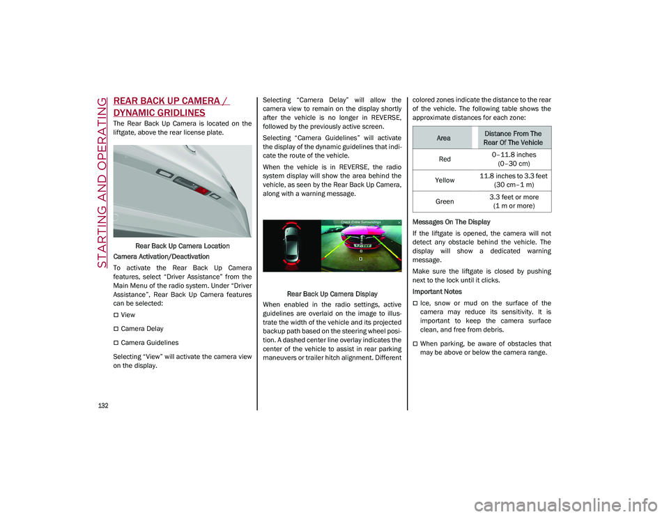
The Rear Back Up Camera is located on the
liftgate, above the rear license plate.Rear Back Up Camera Location
Camera Activation/Deactivation
To activate the Rear Back Up Camera
features, select “Driver Assistance” from the
Main Menu of the radio system. Under “Driver
Assistance”, Rear Back Up Camera features
can be selected:
View
Camera Delay
Camera Guidelines
Selecting “View” will activate the camera view
on the display. Selecting “Camera Delay” will allow the
camera view to remain on the display shortly
after the vehicle is no longer in REVERSE,
followed by the previously active screen.
Selecting “Camera Guidelines” will activate
the display of the dynamic guidelines that indi
-
cate the route of the vehicle.
When the vehicle is in REVERSE, the radio
system display will show the area behind the
vehicle, as seen by the Rear Back Up Camera,
along with a warning message.
Rear Back Up Camera Display
When enabled in the radio settings, active
guidelines are overlaid on the image to illus -
trate the width of the vehicle and its projected
backup path based on the steering wheel posi -
tion. A dashed center line overlay indicates the
center of the vehicle to assist in rear parking
maneuvers or trailer hitch alignment. Different colored zones indicate the distance to the rear
of the vehicle. The following table shows the
approximate distances for each zone:
Messages On The Display
If the liftgate is opened, the camera will not
detect any obstacle behind the vehicle. The
display will show a dedicated warning
message.
Make sure the liftgate is closed by pushing
next to the lock until it clicks.
Important Notes
Ice, snow or mud on the surface of the
camera may reduce its sensitivity. It is
important to keep the camera surface
clean, and free from debris.
When parking, be aware of obstacles that
may be above or below the camera range.
AreaDistance From The
Rear Of The Vehicle
Red 0–11.8 inches
(0–30 cm)
Yellow 11.8 inches to 3.3 feet
(30 cm–1 m)
Green 3.3 feet or more
(1 m or more)
21_GU_OM_EN_USC_t.book Page 132
Page 146 of 280

STARTING AND OPERATING
144
Preheating the carbon ceramic material brake
discs
The brake discs must be warmed up to make
them fully efficient. You are advised to perform
the following procedure to achieve optimal
efficiency:
Brake nine times from 80 mph to 18 mph
(130 km/h to 30 km/h) with deceleration
equal to 0.7g (the longitudinal acceleration
value is shown on the instrument cluster
display by setting RACE mode and selecting
the “Performance” page) with 20 second
intervals between brake applications; keep
the car at a speed comprised between
37 mph and 62 mph (60 km/h and
100 km/h) and do not brake for 4 minutes to allow the brakes to cool down.
Then brake three times from 124 mph to
18 mph (200 km/h to 30 km/h) with decel -
eration equal to 1.1g (ABS operation) with
30 second intervals between brake applica -
tions; keep the car at a speed comprised
between 37 mph and 62 mph (60 km/h
and 100 km/h) and do not brake for
5 minutes to allow the brakes to cool down.
21_GU_OM_EN_USC_t.book Page 144
Page 149 of 280
147
Hill Descent Control (HDC) System — If
Equipped
The HDC function is an integral part of the
Electronic Stability Control (ESC) system,
keeping the vehicle at a constant speed while
descending a hill by actively controlling the
brakes.
HDC aims to create vehicle stability and safer
driving in various situations, including poor
grip conditions and steep descents.
The system has three different modes:
Off: the system is deactivated
Enabled: the system is enabled and ready to
intervene when the activation conditions
are met
Active: the system actively controls the
vehicle speed
Enabling The System
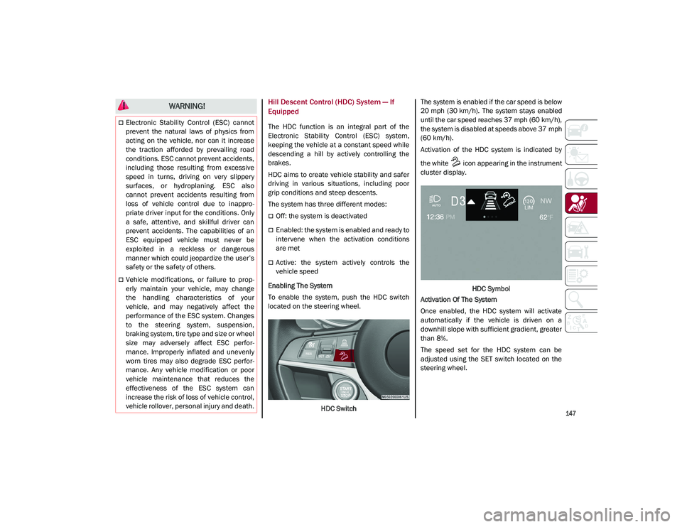
To enable the system, push the HDC switch
located on the steering wheel.
HDC Switch The system is enabled if the car speed is below
20 mph (30 km/h). The system stays enabled
until the car speed reaches 37 mph (60 km/h),
the system is disabled at speeds above 37 mph
(60 km/h).
Activation of the HDC system is indicated by
the white icon appearing in the instrument
cluster display.
HDC Symbol
Activation Of The System
Once enabled, the HDC system will activate
automatically if the vehicle is driven on a
downhill slope with sufficient gradient, greater
than 8%.
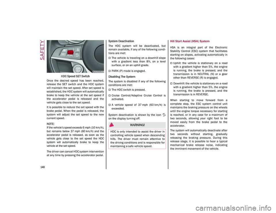
The speed set for the HDC system can be
adjusted using the SET switch located on the
steering wheel.
WARNING!
Electronic Stability Control (ESC) cannot
prevent the natural laws of physics from
acting on the vehicle, nor can it increase
the traction afforded by prevailing road
conditions. ESC cannot prevent accidents,
including those resulting from excessive
speed in turns, driving on very slippery
surfaces, or hydroplaning. ESC also
cannot prevent accidents resulting from
loss of vehicle control due to inappro -
priate driver input for the conditions. Only
a safe, attentive, and skillful driver can
prevent accidents. The capabilities of an
ESC equipped vehicle must never be
exploited in a reckless or dangerous
manner which could jeopardize the user’s
safety or the safety of others.
Vehicle modifications, or failure to prop -
erly maintain your vehicle, may change
the handling characteristics of your
vehicle, and may negatively affect the
performance of the ESC system. Changes
to the steering system, suspension,
braking system, tire type and size or wheel
size may adversely affect ESC perfor-
mance. Improperly inflated and unevenly
worn tires may also degrade ESC perfor -
mance. Any vehicle modification or poor
vehicle maintenance that reduces the
effectiveness of the ESC system can
increase the risk of loss of vehicle control,
vehicle rollover, personal injury and death.
21_GU_OM_EN_USC_t.book Page 147
Page 150 of 280
SAFETY
148
HDC Speed SET Switch
Once the desired speed has been reached,
release the SET switch and the HDC system
will maintain the set speed. After set speed is
established, the HDC system will automatically
brake to keep the vehicle at the set speed if
the accelerator pedal is released and the
vehicle gets close to the set speed.
It is possible to reduce the set speed with the
brake pedal. When the pedal is released, the
system will adjust the set speed to the new
current speed.
NOTE:
If the vehicle’s speed exceeds 6 mph (10 km/h),
but remains below 37 mph (60 km/h) and the
accelerator pedal is released, as soon as the
vehicle gets close to the set speed the HDC
system will automatically brake to keep the
vehicle at the set speed.
The driver can cancel HDC system intervention
at any time by pressing the accelerator pedal. System Deactivation
The HDC system will be deactivated, but
remain available, if any of the following condi
-
tions are met:
The vehicle is traveling on a downhill slope
with a gradient less than 8%, on a level
surface, or on an uphill grade.
PARK (P) mode is engaged.
Disabling The System
The system is disabled if any of the following
conditions are met:
The HDC switch is pressed.
Cruise Control/Adaptive Cruise Control is
activated.
A vehicle speed of 37 mph (60 km/h) is
exceeded.
System deactivation is shown by the icon
on the display turning off.
Hill Start Assist (HSA) System
HSA is an integral part of the Electronic
Stability Control (ESC) system that facilitates
starting on slopes, activating automatically in
the following cases:
Uphill: the vehicle is stationary on a road
with a gradient higher than 5%, the engine
is running, the brake is pressed, and the
transmission is in NEUTRAL (N) or a gear
other than REVERSE (R) is engaged.
Downhill: the vehicle is stationary on a road
with a gradient higher than 5%, the engine
is running, the brake is pressed, and the
transmission is in REVERSE.
When starting to move forward from a
complete stop, the ESC system control unit
maintains the braking pressure on the wheels
until the engine torque necessary for starting
is reached, or in any case for a maximum of
two seconds, allowing your right foot to be
moved easily from the brake pedal to the
accelerator.
The system will automatically deactivate after
two seconds without starting, gradually
releasing the braking pressure. During this
release stage, it is possible to hear a typical
mechanical brake release noise, indicating
the imminent movement of the vehicle.
WARNING!
HDC is only intended to assist the driver in
controlling vehicle speed when descending
hills. The driver must remain attentive to
the driving conditions and is responsible for
maintaining a safe vehicle speed.
21_GU_OM_EN_USC_t.book Page 148
Page 155 of 280
153
The sensors are activated when any forward
gear is engaged at a speed higher than about
6 mph (10 km/h), or when REVERSE (R) is
engaged.
The sensors are temporarily deactivated when
the car is stationary and in PARK (P).
The detection area of the system covers about
a lane on both sides of the car around 10 ft
(3 meters).
This area begins from the door mirror and
extends for about 20 ft (6 meters) towards the
rear part of the car.
When the sensors are active the system moni-
tors the detection areas on both sides of the
car and warns the driver about the possible
presence of cars in these areas.
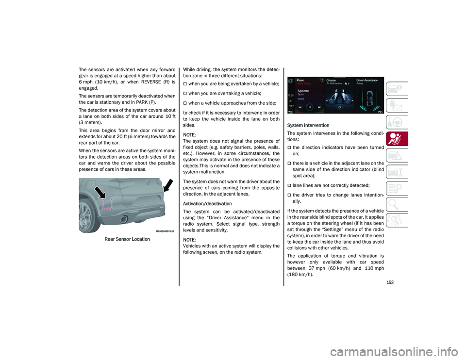
Rear Sensor Location While driving, the system monitors the detec
-
tion zone in three different situations:
when you are being overtaken by a vehicle;
when you are overtaking a vehicle;
when a vehicle approaches from the side;
to check if it is necessary to intervene in order
to keep the vehicle inside the lane on both
sides.
NOTE:
The system does not signal the presence of
fixed object (e.g. safety barriers, poles, walls,
etc.). However, in some circumstances, the
system may activate in the presence of these
objects.This is normal and does not indicate a
system malfunction.
The system does not warn the driver about the
presence of cars coming from the opposite
direction, in the adjacent lanes.
Activation/deactivation
The system can be activated/deactivated
using the “Driver Assistance” menu in the
radio system. Select signal type, strength
levels and sensitivity.
NOTE:
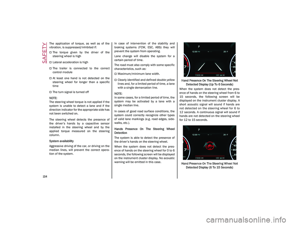
Vehicles with an active system will display the
following screen, on the radio system. System intervention
The system intervenes in the following condi
-
tions:
the direction indicators have been turned
on;
there is a vehicle in the adjacent lane on the
same side of the direction indicator (blind
spot area);
lane lines are not correctly detected;
the driver tries to change lanes intention -
ally.
If the system detects the presence of a vehicle
in the rear side blind spots of the car, it applies
a torque on the steering wheel (if it has been
set through the “Settings” menu of the radio
system), in order to warn the driver of the need
to keep the car inside the lane and thus avoid
collisions with other vehicles.
The application of torque and vibration is
however only available with car speed
between 37 mph (60 km/h) and 110 mph
(180 km/h).
21_GU_OM_EN_USC_t.book Page 153
Page 156 of 280
SAFETY
154
The application of torque, as well as of the
vibration, is suppressed/inhibited if:
The torque given by the driver of the
steering wheel is high
Lateral acceleration is high
The trailer is connected to the correct
control module
At least one hand is not detected on the
steering wheel for longer than a specific
time
The turn signal is turned off
NOTE:
The steering wheel torque is not applied if the
system is unable to detect a lane and if the
direction indicator for the appropriate side has
not been switched on.
The steering wheel detects the presence of
the driver’s hands by a capacitive sensor
installed in the steering wheel and by the
applied torque measured on the steering
column.
System availability
Aggressive driving of the car, or driving on the
median lines, will prevent the correct opera -
tion of the system. In case of intervention of the stability and
braking systems (FCW, ESC, ABS) they will
prevent the system from operating.
Lane change will disable the system for a
certain period of time.
The road must also comply with some specific
characteristics, such as:
Maximum/minimum lane width.
Clearly identified and defined double yellow
lines and, for a limited period of time, a lane
with a single demarcation line.
NOTE:
In some cases, for a limited period of time, the
system may be activated by a lane with a
single median line.
In cases of good road surface conditions, the
system could correctly recognize other types
of valid lane markings (e.g. road edges, side -
walks, etc.).
Hands Presence On The Steering Wheel
Detection
The system is able to detect the presence of
the driver’s hands on the steering wheel.
When the system does not detect the pres -
ence of hands on the steering wheel for 0 to 6
seconds, the following screen will be displayed
on the instrument cluster display. No acoustic
warning will be emitted in this case. Hand Presence On The Steering Wheel Not
Detected Display (Up To 6 Seconds)
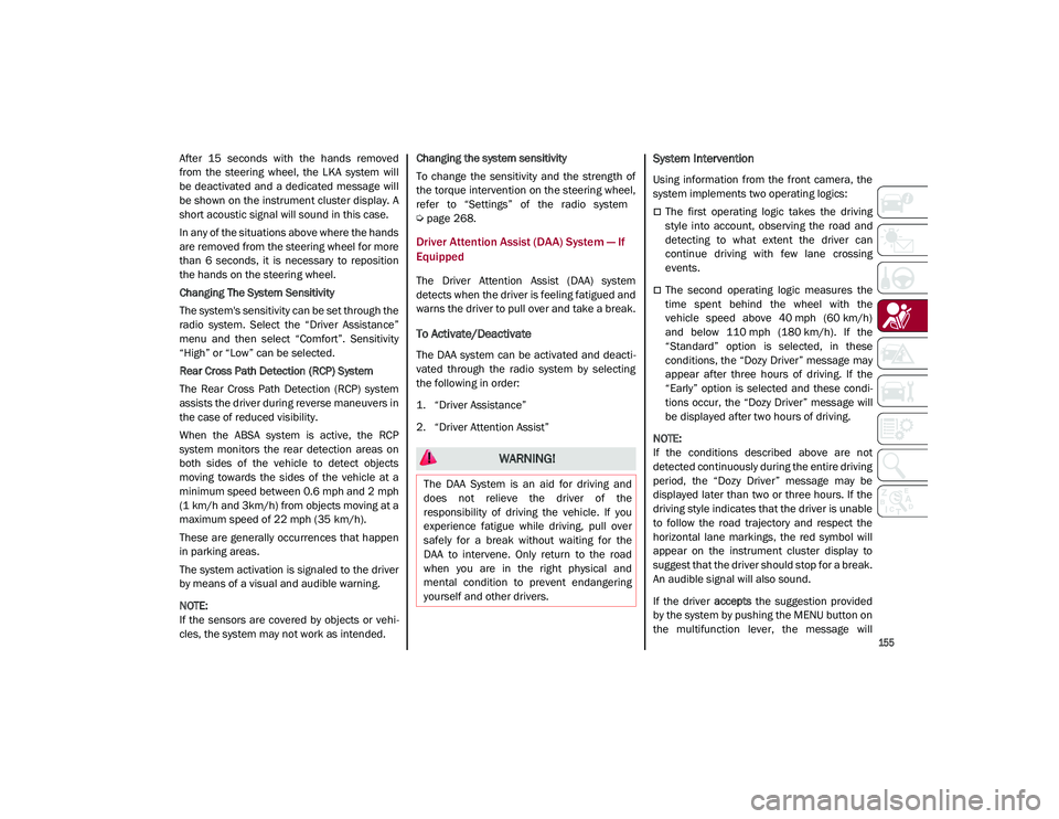
When the system does not detect the pres -
ence of hands on the steering wheel from 6 to
15 seconds, the following screen will be
displayed on the instrument cluster display. A
short acoustic signal will sound if hands are
not detected on the steering wheel for 6 to
12 seconds. A continuous signal will sound if
hands are not detected on the steering wheel
for 12 to 15 seconds.
Hand Presence On The Steering Wheel Not Detected Display (6 To 15 Seconds)
21_GU_OM_EN_USC_t.book Page 154
Page 157 of 280
155
After 15 seconds with the hands removed
from the steering wheel, the LKA system will
be deactivated and a dedicated message will
be shown on the instrument cluster display. A
short acoustic signal will sound in this case.
In any of the situations above where the hands
are removed from the steering wheel for more
than 6 seconds, it is necessary to reposition
the hands on the steering wheel.
Changing The System Sensitivity
The system's sensitivity can be set through the
radio system. Select the “Driver Assistance”
menu and then select “Comfort”. Sensitivity
“High” or “Low” can be selected.
Rear Cross Path Detection (RCP) System
The Rear Cross Path Detection (RCP) system
assists the driver during reverse maneuvers in
the case of reduced visibility.
When the ABSA system is active, the RCP
system monitors the rear detection areas on
both sides of the vehicle to detect objects
moving towards the sides of the vehicle at a
minimum speed between 0.6 mph and 2 mph
(1 km/h and 3km/h) from objects moving at a
maximum speed of 22 mph (35 km/h).
These are generally occurrences that happen
in parking areas.
The system activation is signaled to the driver
by means of a visual and audible warning.
NOTE:
If the sensors are covered by objects or vehi-
cles, the system may not work as intended. Changing the system sensitivity
To change the sensitivity and the strength of
the torque intervention on the steering wheel,
refer to “Settings” of the radio system
Ú
page 268.
Driver Attention Assist (DAA) System — If
Equipped
The Driver Attention Assist (DAA) system
detects when the driver is feeling fatigued and
warns the driver to pull over and take a break.
To Activate/Deactivate
The DAA system can be activated and deacti -
vated through the radio system by selecting
the following in order:
1. “Driver Assistance”
2. “Driver Attention Assist”
System Intervention
Using information from the front camera, the
system implements two operating logics:
The first operating logic takes the driving
style into account, observing the road and
detecting to what extent the driver can
continue driving with few lane crossing
events.
The second operating logic measures the
time spent behind the wheel with the
vehicle speed above 40 mph (60 km/h) and below 110 mph (180 km/h). If the“Standard” option is selected, in these
conditions, the “Dozy Driver” message may
appear after three hours of driving. If the
“Early” option is selected and these condi -
tions occur, the “Dozy Driver” message will
be displayed after two hours of driving.
NOTE:
If the conditions described above are not
detected continuously during the entire driving
period, the “Dozy Driver” message may be
displayed later than two or three hours. If the
driving style indicates that the driver is unable
to follow the road trajectory and respect the
horizontal lane markings, the red symbol will
appear on the instrument cluster display to
suggest that the driver should stop for a break.
An audible signal will also sound.
If the driver accepts the suggestion provided
by the system by pushing the MENU button on
the multifunction lever, the message will
WARNING!
The DAA System is an aid for driving and
does not relieve the driver of the
responsibility of driving the vehicle. If you
experience fatigue while driving, pull over
safely for a break without waiting for the
DAA to intervene. Only return to the road
when you are in the right physical and
mental condition to prevent endangering
yourself and other drivers.
21_GU_OM_EN_USC_t.book Page 155
Page 158 of 280
SAFETY
156
disappear from the display and the symbol will
be displayed in the dedicated area of the
instrument cluster display until the next
engine shutdown.
If the driver ignores the warning provided by
the system and does not stop, the message
will continue to remain on the display, along
with the symbol.
NOTE:
In the event of a DAA system failure, an
amber symbol will appear in the instrument
cluster display along with a dedicated
message.
If the ABS system activates, “ABS ACTIVE”
will display in place of the DAA symbol and
will remain active until the ABS system
deactivates.
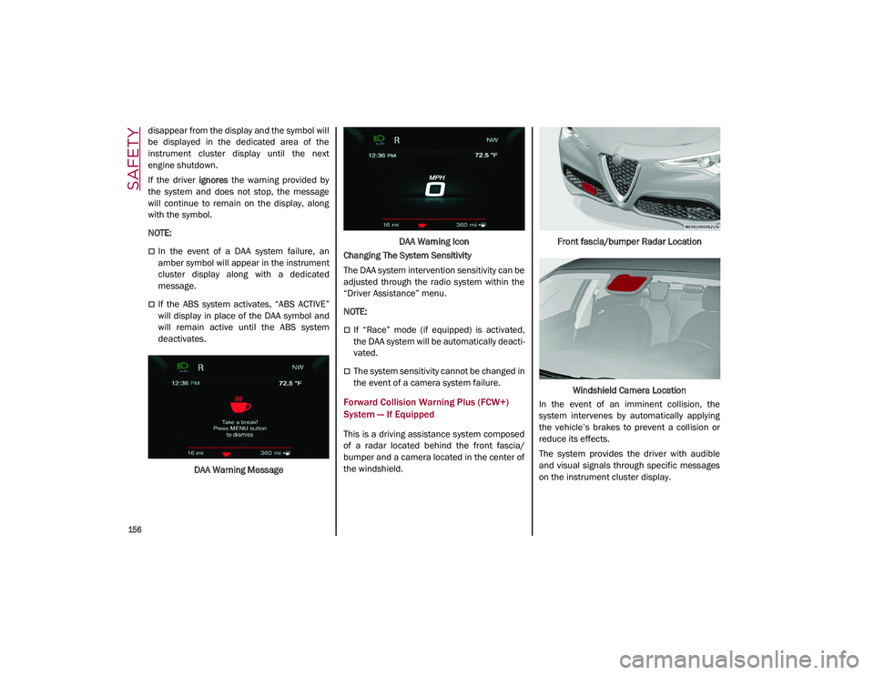
DAA Warning Message DAA Warning Icon
Changing The System Sensitivity
The DAA system intervention sensitivity can be
adjusted through the radio system within the
“Driver Assistance” menu.
NOTE:
If “Race” mode (if equipped) is activated,
the DAA system will be automatically deacti -
vated.
The system sensitivity cannot be changed in
the event of a camera system failure.
Forward Collision Warning Plus (FCW+)
System — If Equipped
This is a driving assistance system composed
of a radar located behind the front fascia/
bumper and a camera located in the center of
the windshield. Front fascia/bumper Radar Location
Windshield Camera Location
In the event of an imminent collision, the
system intervenes by automatically applying
the vehicle’s brakes to prevent a collision or
reduce its effects.
The system provides the driver with audible
and visual signals through specific messages
on the instrument cluster display.
21_GU_OM_EN_USC_t.book Page 156
Page 160 of 280
SAFETY
158
Activation/Deactivation
The Forward Collision Warning system is acti-
vated whenever the engine is started regard -
less of what is shown on the radio system.
Following a deactivation, the system will not
warn the driver about the possible collision
with a preceding vehicle, regardless of the
setting selected in the radio system.
NOTE:
Each time the engine is started, the system is
activated regardless of what setting was
selected when the engine was turned off.
This function is not active at a speed lower
than 4 mph (7 km/h) or higher than 124 mph
(200 km/h).
The system is active:
Each time the engine is started
When feature is selected within the radio
system
When the ignition is in the ON position
When the vehicle speed is between 2 mph
(4 km/h) and 124 mph (200 km/h)
When the front seat belts are fastened
The "Alfa DNA Pro" selector is not in RACE
position (if equipped)
NOTE:
If the seat belts of the front seats are not
correctly fastened, the system will not inter -vene on the braking system (only audible and
visual signals will be provided).
Changing The System Sensitivity
The sensitivity of the system can be changed
through the Information and Entertainment
system menu, choosing from one of the
following three options: "Near", "Medium" or
"Far". Refer to the description in the Informa
-
tion and Entertainment system Supplement
for how to change the settings.
The default setting is "Medium". With this
setting, the system warns the driver of a
possible collision with the vehicle in front
when that vehicle is at a standard distance,
between that of the other two settings.
With the system sensitivity set to "Far", the
system will warn the driver of a possible colli -
sion with the vehicle in front when that vehicle
is at a greater distance, thus providing the
possibility of acting on the brakes more lightly
and gradually. This setting provides the driver
with the maximum possible reaction time to
prevent a potential collision.
With the option set to "Near", the system will
alert the driver of a possible collision with the
vehicle in front when that vehicle is close. This
setting offers the driver a lower reaction time
compared to the "Medium" and "Far" settings,
in the event of a potential collision, but
permits more dynamic driving of the vehicle.
The system sensitivity setting is kept in the
memory when the engine is turned off. System Limited Operation Warning
If a dedicated message is displayed, a condi
-
tion limiting the system operation may have
occurred. The possible reasons of this limita -
tion are something is blocking the camera
view or a fault.
If an obstruction is signaled, clean the area of
the radar on the front fascia/bumper, and the
camera area on the windshield.
If a fault in the system is occurring, it will still
be possible to drive the vehicle normally, but
automatic braking will not be available in the
event of an impending collision.
When the conditions limiting the system func -
tions end, this will go back to normal and
complete operation. Should the fault persist,
contact an authorized dealer.
System Failure Signaling
If the system turns off and a dedicated
message is shown on the display, it means
that there is a fault with the system.
In this case, it is still possible to drive the
vehicle, but you are advised to contact an
authorized dealer as soon as possible.
Radar Indication Not Available
If conditions are such that the radar cannot
detect obstacles correctly, the system is deac -
tivated and a dedicated message appears on
the display. This generally occurs in the event
of poor visibility, such as when it is snowing or
raining heavily.
21_GU_OM_EN_USC_t.book Page 158