climate control ALFA ROMEO STELVIO 2021 Owners Manual
[x] Cancel search | Manufacturer: ALFA ROMEO, Model Year: 2021, Model line: STELVIO, Model: ALFA ROMEO STELVIO 2021Pages: 280, PDF Size: 10.02 MB
Page 11 of 280
9
Automatic High Beam Headlights —
If Equipped ............................................. 43 Parking Lights ....................................... 44
Headlight Off Delay ................................ 44
Rear Fog Lights ...................................... 44
Adaptive Headlight System (AFS) —
If Equipped ............................................. 44 Turn Signals ........................................ 44
Lane Change Assist ............................... 44
INTERIOR LIGHTS .....................................44
Front Map Reading Lights ..................... 45
Interior Ambient Lighting ...................... 45
Rear Overhead Light ............................. 46
Instrument Panel Dimmer Control ....... 46
WINDSHIELD WIPERS AND WASHERS....46
Windshield Wiper Operation ............... 46
Rain Sensing Wipers.............................. 47
Rear Window Wiper/Washer................. 48
Headlamp Washers — If Equipped ....... 48
CLIMATE CONTROLS ................................48
Automatic Dual-Zone Climate Control
System ................................................. 49
INTERIOR STORAGE AND EQUIPMENT....55
Glove Compartment............................... 55
Center Console ...................................... 56
Rear Armrest .......................................... 56
Power Outlets ...................................... 56
Cigar Lighter And Ash Tray —
If Equipped ............................................. 57 Wireless Charging Pad — If Equipped... 57
POWER WINDOWS ................................... 58
Power Window Controls ........................ 58
Auto-Up Feature With Anti-Pinch
Protection............................................... 59 Power Window System Initialization .... 59
Wind Buffeting ...................................... 59
POWER SUNROOF — IF EQUIPPED.......... 59
Power Sunroof ....................................... 59
Opening And Closing The Sunroof ........ 60
Venting Sunroof ..................................... 60
Sunshade Operation ............................. 60
Pinch Protect Feature ........................... 60
Re-Initialization Procedure.................... 60
Sunroof Maintenance ........................... 61
HOOD ........................................................ 61
Opening The Hood ................................. 61
Closing The Hood................................... 62
POWER LIFTGATE..................................... 62
Opening .................................................. 62
Closing.................................................... 63
Liftgate Initialization .............................. 64
Cargo Area Features ............................. 64
GETTING TO KNOW YOUR INSTRUMENT
PANEL
INSTRUMENT PANEL FEATURES............. 67
Instrument Cluster ............................... 67
Instrument Cluster Descriptions .......... 68
INSTRUMENT CLUSTER DISPLAY ............69
Instrument Cluster Display
Description .............................................69 Reconfigurable Instrument Cluster
Display ....................................................69 Reconfigurable Display Items ............... 69
Customer Programmable Settings........ 72
WARNING LIGHTS AND MESSAGES
ON THE INSTRUMENT PANEL ..................74
Red Warning Lights ................................74
Amber Warning Lights............................ 75
Green Indicator Lights ...........................78
Blue Indicator Lights ..............................78
Red Symbols...........................................78
Amber Symbols ......................................80
Green Symbols .......................................84
Blue Symbols .......................................... 84
ONBOARD DIAGNOSTIC SYSTEM ............84
Onboard Diagnostic System (OBD II)
Cybersecurity .......................................... 84
EMISSIONS INSPECTION AND
MAINTENANCE PROGRAM .......................85
21_GU_OM_EN_USC_t.book Page 9
Page 23 of 280
21
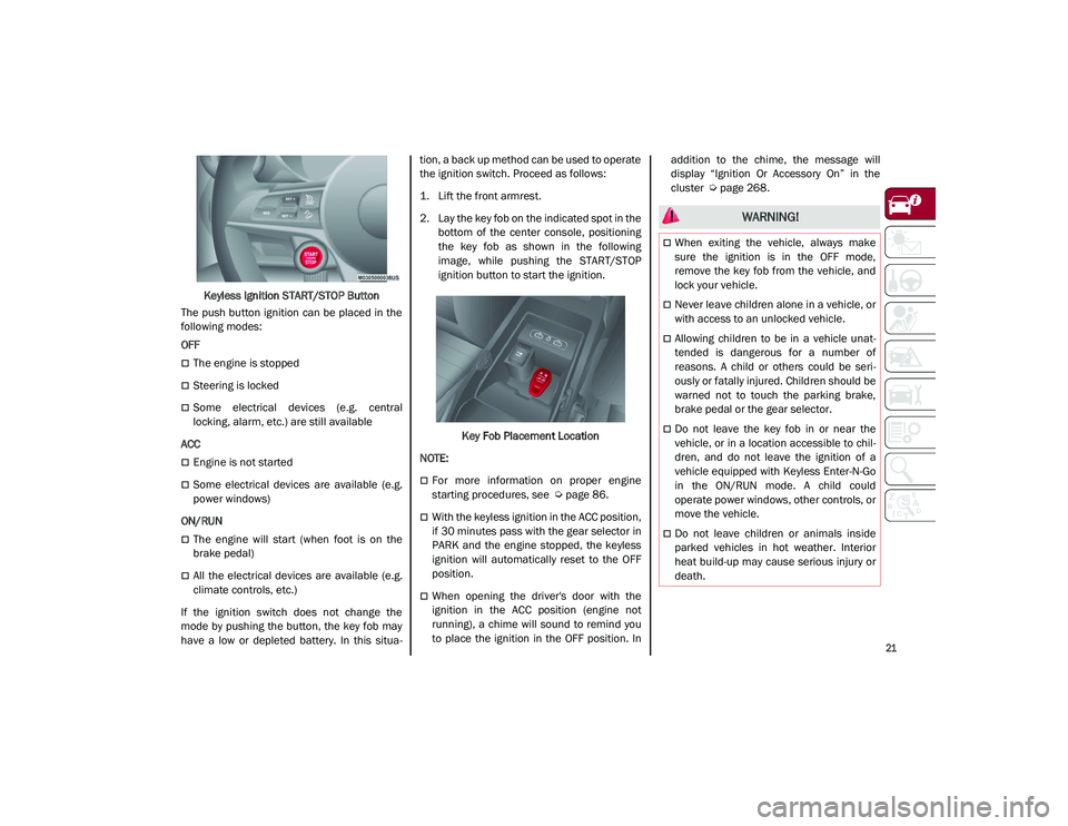
Keyless Ignition START/STOP Button
The push button ignition can be placed in the
following modes:
OFF
The engine is stopped
Steering is locked
Some electrical devices (e.g. central
locking, alarm, etc.) are still available
ACC
Engine is not started
Some electrical devices are available (e.g.
power windows)
ON/RUN
The engine will start (when foot is on the
brake pedal)
All the electrical devices are available (e.g.
climate controls, etc.)
If the ignition switch does not change the
mode by pushing the button, the key fob may
have a low or depleted battery. In this situa -tion, a back up method can be used to operate
the ignition switch. Proceed as follows:
1. Lift the front armrest.
2. Lay the key fob on the indicated spot in the
bottom of the center console, positioning
the key fob as shown in the following
image, while pushing the START/STOP
ignition button to start the ignition.
Key Fob Placement Location
NOTE:
For more information on proper engine
starting procedures, see
Ú
page 86.
With the keyless ignition in the ACC position,
if 30 minutes pass with the gear selector in
PARK and the engine stopped, the keyless
ignition will automatically reset to the OFF
position.
When opening the driver's door with the
ignition in the ACC position (engine not
running), a chime will sound to remind you
to place the ignition in the OFF position. In addition to the chime, the message will
display “Ignition Or Accessory On” in the
cluster
Ú
page 268.
WARNING!
When exiting the vehicle, always make
sure the ignition is in the OFF mode,
remove the key fob from the vehicle, and
lock your vehicle.
Never leave children alone in a vehicle, or
with access to an unlocked vehicle.
Allowing children to be in a vehicle unat -
tended is dangerous for a number of
reasons. A child or others could be seri -
ously or fatally injured. Children should be
warned not to touch the parking brake,
brake pedal or the gear selector.
Do not leave the key fob in or near the
vehicle, or in a location accessible to chil -
dren, and do not leave the ignition of a
vehicle equipped with Keyless Enter-N-Go
in the ON/RUN mode. A child could
operate power windows, other controls, or
move the vehicle.
Do not leave children or animals inside
parked vehicles in hot weather. Interior
heat build-up may cause serious injury or
death.
21_GU_OM_EN_USC_t.book Page 21
Page 36 of 280

GETTING TO KNOW YOUR VEHICLE
34
Seat Cushion Extension — If Equipped
Lift the adjustment lever and push the front of
the cushion forward or rearward to extend the
cushion by a few inches (centimeters).Seat Cushion Extension
Power Bolster Adjustment — If Equipped
Push the power bolster adjustment buttons to
regulate the width of the backrest through the
lateral padding.
Easy Entry Function
The Easy Entry function is designed to move
the driver side seat forward automatically by
2.36 inches (60 mm) to make it easier for the
driver to get in and out of the car.
The movement is activated only if the seat is
set to a driving position which is in front of the
B-pillar of the vehicle. The function is associated with power driver
seats for each of the three stored positions.
The Easy Entry function can be activated/
deactivated through the radio system. Refer to
the Information and Entertainment System
Owner’s Manual Supplement for further infor
-
mation.
Heated Seats — If Equipped
For information on use with the Remote Start
system, see
Ú
page 23.
Front Heated Seats — If Equipped
NOTE:
Quadrifoglio vehicles equipped with Sparco
Racing Seats will not be equipped with the
heated seat feature.
A push of the heated seat buttons located on
the instrument panel, near the climate
controls, will select the heat levels in order of
highest to lowest. A fourth push of the button
will turn the heated seat off.
NOTE:
The heated seat function can also be activated
through the radio system. Refer to the Infor -
mation and Entertainment System Owner’s
Manual Supplement for further information.
You can select three heating levels:
Maximum — three LED indicators illumi -
nated on the buttons
Average — two LED indicators illuminated
on the buttons
Minimum — one LED indicator illuminated
on the buttons
Heated Seat Buttons
6 — Adjustment Lever
WARNING!
Persons who are unable to feel pain to the
skin because of advanced age, chronic
illness, diabetes, spinal cord injury, medi
-
cation, alcohol use, exhaustion or other
physical condition must exercise care
when using the seat heater. It may cause
burns even at low temperatures, espe -
cially if used for long periods of time.
Do not place anything on the seat or seat -
back that insulates against heat, such as
a blanket or cushion. This may cause the
seat heater to overheat. Sitting in a seat
that has been overheated could cause
serious burns due to the increased
surface temperature of the seat.
21_GU_OM_EN_USC_t.book Page 34
Page 41 of 280
39
If the door mirrors were folded using the power
mirror control knob, they can only be returned
to the driving position by moving the knob to
the power folding position again.
NOTE:
The power folding operation can be enabled
only when the vehicle speed is lower than
31 mph (50 km/h).
Outside Automatic Dimming Mirrors — If
Equipped
The outside mirrors will automatically dim for
glare from vehicles behind you. This feature is
controlled by the inside automatic dimming
mirror. The mirrors will automatically adjust for
headlight glare when the inside mirror adjusts.
Heated Mirrors
Push the rear defrost button, located within
the climate controls, to activate the heated
mirrors.
UNIVERSAL GARAGE DOOR
OPENER (HOMELINK®)
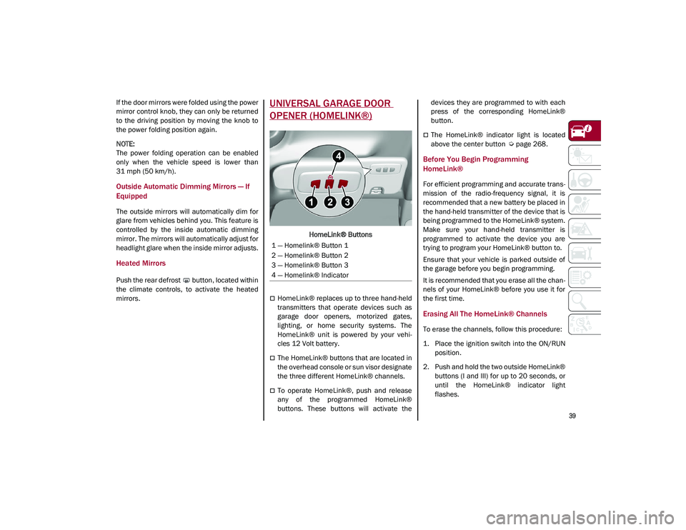
HomeLink® Buttons
HomeLink® replaces up to three hand-held
transmitters that operate devices such as
garage door openers, motorized gates,
lighting, or home security systems. The
HomeLink® unit is powered by your vehi-
cles 12 Volt battery.
The HomeLink® buttons that are located in
the overhead console or sun visor designate
the three different HomeLink® channels.
To operate HomeLink®, push and release
any of the programmed HomeLink®
buttons. These buttons will activate the devices they are programmed to with each
press of the corresponding HomeLink®
button.
The HomeLink® indicator light is located
above the center button
Ú
page 268.
Before You Begin Programming
HomeLink®
For efficient programming and accurate trans -
mission of the radio-frequency signal, it is
recommended that a new battery be placed in
the hand-held transmitter of the device that is
being programmed to the HomeLink® system.
Make sure your hand-held transmitter is
programmed to activate the device you are
trying to program your HomeLink® button to.
Ensure that your vehicle is parked outside of
the garage before you begin programming.
It is recommended that you erase all the chan -
nels of your HomeLink® before you use it for
the first time.
Erasing All The HomeLink® Channels
To erase the channels, follow this procedure:
1. Place the ignition switch into the ON/RUN position.
2. Push and hold the two outside HomeLink® buttons (I and III) for up to 20 seconds, or
until the HomeLink® indicator light
flashes.
1 — Homelink® Button 1
2 — Homelink® Button 2
3 — Homelink® Button 3
4 — Homelink® Indicator
21_GU_OM_EN_USC_t.book Page 39
Page 50 of 280
GETTING TO KNOW YOUR VEHICLE
48
If the windshield washer is used with the rain
sensor activated, the normal washing cycle is
performed, and then the rain sensor resumes
its normal automatic operation.
NOTE:
Keep the glass in the sensor area clean.
Deactivation
To turn off the Rain Sensing Wipers, use the
wiper switch or place the ignition in the OFF
position.
In the event of malfunction of the rain sensor
while it is active, the windshield wiper oper-
ates intermittently at a speed consistent with
the sensitivity setting of the rain sensor,
whether or not there is rain on the glass for as
long as the sensor failure is indicated on the
display.
The sensor continues to operate and it is
possible to set the windshield wiper to contin -
uous mode (1 or 2). The failure indication
remains on for as long as the sensor is active. The rain sensor is able to recognize and auto
-
matically adjust itself in the presence of the
following conditions:
Presence of dirt on the controlled surface
(e.g. salt, dirt, etc.).
Presence of streaks of water caused by the
worn window wiper blades.
Difference between day and night.
Rear Window Wiper/Washer
Push the windshield wiper lever downward to
activate/deactivate continuous rear wiper
operation.
Push the windshield wiper lever towards the
instrument panel to activate the rear window
washer (a brief push activates one washing
cycle, keeping the stalk pushed washes
continuously until the stalk is released).
Shifting the vehicle into REVERSE with the
windshield wiper operating activates a single
cycle of the rear window wiper.
Headlamp Washers — If Equipped
The windshield wiper lever operates the head -
light washers when the ignition is in the ON
position and the headlights are turned on. To
use the headlight washers, pull the lever
toward you and release it. The headlight
washers will spray a timed high-pressure spray
of washer fluid onto each headlight lens. In
addition, the windshield washers will spray the
windshield and the windshield wipers will
cycle.
NOTE:
The headlight washers work on every tenth
wash cycle request.
CLIMATE CONTROLS
The Climate Control system allows you to regu -
late the temperature, air flow, and direction of
air circulating throughout the vehicle. The
controls are located on the touchscreen and
on the instrument panel below the radio.
21_GU_OM_EN_USC_t.book Page 48
Page 51 of 280
49
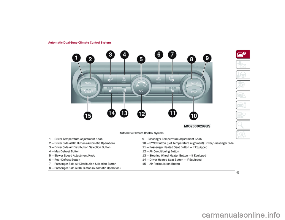
Automatic Dual-Zone Climate Control System
Automatic Climate Control System
1 — Driver Temperature Adjustment Knob 9 — Passenger Temperature Adjustment Knob
2 — Driver Side AUTO Button (Automatic Operation) 10 — SYNC Button (Set Temperature Alignment) Driver/Passenger Side
3 — Driver Side Air Distribution Selection Button 11 — Passenger Heated Seat Button — If Equipped
4 — Max Defrost Button 12 — Air Conditioning Button
5 — Blower Speed Adjustment Knob 13 — Steering Wheel Heater Button — If Equipped
6 — Rear Defrost Button 14 — Driver Heated Seat Button — If Equipped
7 — Passenger Side Air Distribution Selection Button 15 — Air Recirculation Button
8 — Passenger Side AUTO Button (Automatic Operation)
21_GU_OM_EN_USC_t.book Page 49
Page 52 of 280
GETTING TO KNOW YOUR VEHICLE
50
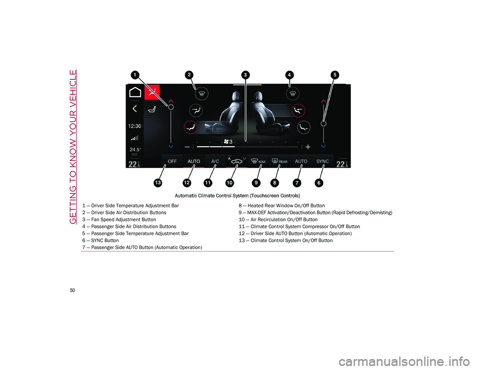
Automatic Climate Control System (Touchscreen Controls)
1 — Driver Side Temperature Adjustment Bar 8 — Heated Rear Window On/Off Button
2 — Driver Side Air Distribution Buttons 9 — MAX-DEF Activation/Deactivation Button (Rapid Defrosting/Demisting)
3 — Fan Speed Adjustment Button 10 — Air Recirculation On/Off Button
4 — Passenger Side Air Distribution Buttons 11 — Climate Control System Compressor On/Off Button
5 — Passenger Side Temperature Adjustment Bar 12 — Driver Side AUTO Button (Automatic Operation)
6 — SYNC Button 13 — Climate Control System On/Off Button
7 — Passenger Side AUTO Button (Automatic Operation)
21_GU_OM_EN_USC_t.book Page 50
Page 53 of 280
51
Description
The Automatic Dual Zone Climate Control
System adjusts the temperature and air distri-
bution independently between the driver and
passenger.
The system maintains the set temperature
inside the passenger compartment and
compensates for outside temperature change.
NOTE:
The reference temperature is 72°F (22°C) for
optimal comfort management.
The automatic setting will adjust the following
to maintain comfort within the passenger
compartment:
Air temperature from the driver/front
passenger side vents
Air distribution from the driver/front
passenger side vents
Fan speed (continuous variation of the air
flow)
Compressor variations (for cooling/dehu -
midifying the air)
Air recirculation
The Climate Control System can also be oper -
ated manually by using the buttons and knobs
on the faceplate.
Manual selections will override the automatic
settings, which are stored until the AUTO
button is pushed. If the system intervenes for
safety reasons, the automatic setting will take
control of the system.
The below operations will not deactivate the
automatic (AUTO) function:
Air Recirculation activation/deactivation
A/C activation/deactivation
SYNC function activation
Rear Window Defrost activation/deactiva -
tion
When in AUTO mode, the vehicle’s internal
temperature is controlled according to the set
temperature.
The following can be manually set or adjusted:
Driver/passenger air temperature
Blower speed (continuous variation)
Air distribution (seven positions for driver
and passenger)
A/C activation
Front Defroster
Air recirculation
Rear Defroster
System deactivation
A/C Compressor
Push the A/C button or the icon to activate or
deactivate the A/C compressor (indicator illu-
minated when activated). The A/C compressor
will remain off even after the engine has
stopped.
When the A/C compressor is turned off, the
system deactivates air recirculation to prevent
the windows from fogging up. If the climate
control system can maintain the temperature,
with the A/C turned off, the AUTO feature will
remain on and the AUTO button indicator light
will not switch off.
To restore automatic control of the A/C
compressor, push the A/C button or the icon or
the AUTO button. With the A/C compressor off,
the air speed can be set manually using the Air
Speed Adjustment Knob.
When the A/C compressor is on, and the
engine is running, air speed cannot be lower
than the minimum speed (only one indicator
light is lit).
CAUTION!
The system uses R1234yf refrigerant,
which does not pollute the environment in
the event of accidental leakage. Under no
circumstances, use R134a and R12 fluids,
which are incompatible with the
components of this system.
21_GU_OM_EN_USC_t.book Page 51
Page 54 of 280
GETTING TO KNOW YOUR VEHICLE
52
NOTE:
When the A/C is off, the Climate Control
system can not produce air that is colder than
the current outside temperature. Under
certain environmental conditions, windows
could fog up rapidly since the air is not dehu-
midified.
Air Recirculation And Air Quality System (AQS)
Air Recirculation is managed
according to the following operating
mode:
Automatic engagement: indicator is illumi -
nated above the “A” on the Air Recirculation
Button
Forced activation (air circulation always
activated): indicator illuminated above the
icon on the Air Recirculation Button
Forced deactivation (air recirculation
always off with intake of outside air): both
indicators not illuminated on the Air Recir-
culation Button
The three operating conditions are obtained by
pushing the Air Recirculation Button in
sequence.
Enabling The Air Quality System (AQS) Func -
tion — If Equipped
When the automatic recirculation function is
selected, the AQS function automatically acti -
vates internal air recirculation when the
outside air is polluted (e.g. in heavy traffic and
tunnels). At low external temperatures or in high
humidity, the automatic function turns off to
avoid fogging up the windows. The user can
select the function again by pushing the Air
Recirculation Button.
In automatic operation, air recirculation will be
controlled by the system according to outside
environmental conditions.
NOTE:
With the AQS function active and after the
internal air recirculation system has been
functioning for a set amount of time, the
Climate Control System enables air intake
to cycle the air in the passenger compart
-
ment for a set time. The AQS function is
disabled during the air changes.
The engagement of the recirculation system
makes it possible to reach the required
heating or cooling conditions faster. It is,
however, inadvisable to use it on rainy/cold
days as it can increase the possibility of the
windows fogging. When the outside
temperature is low, recirculation is forced
off to prevent the windows from fogging up.
Front Defrost
Air comes from the windshield and
side window demist outlets. Use
Defrost mode with maximum
temperature settings for best wind -
shield and side window defrosting and defog -
ging.
Rear Defrost
Push the Rear Defrost button to acti -
vate (indicators illuminated) the
Rear Defroster.
The Rear Defrost will turn off after 20 minutes
or once the engine is turned off.
NOTE:
To avoid damage, do not apply stickers over
the interior heating filaments of the Rear
Defroster.
Front Defrost And MAX-DEF Function
Push the MAX-DEF button (indicator
illuminated) to defrost the wind -
shield and side windows.
While in MAX-DEF function, the air conditioner
will:
Activate the air conditioner compressor
when the weather allows
Turn air recirculation off
Set the maximum air temperature (HI) on
both the driver and passenger side
Activate a blower speed based on the
temperature of the engine coolant
Adjust the air flow towards the windshield
and front side windows
Activate the Rear Window Defrost
Display the fan speed (indicators illumi -
nated) and current air distribution setting
21_GU_OM_EN_USC_t.book Page 52
Page 55 of 280
53
NOTE:
The MAX-DEF function remains active for
approximately three minutes once the engine
coolant reaches the proper temperature.
When the function is on, AUTO mode will deac-
tivate. The only manual operations possible
are adjusting blower speed and turning off the
Rear Window Defrost.
Pushing the button switches off the
MAX-DEF function.
Air Temperature Adjustment
Rotate the driver or passenger Temperature
Adjustment Knob clockwise for warmer
temperatures or counterclockwise for cooler
temperatures. The set temperatures are
shown on the radio system.
Push the SYNC button to sync the driver and
passenger air temperatures.
Rotate the passenger Temperature Adjust -
ment Knob to cancel the SYNC function. This
will set a new passenger side temperature.
Rotate the Temperature Adjustment Knob fully
clockwise to engage the HI (maximum heating)
setting or fully counterclockwise to engage the
LO (maximum cooling) setting. To deactivate
these functions, rotate the Temperature
Adjustment Knob to the desired temperature.
Rear passengers’ temperature is linked to
driver side selection.
AUTO Button
When the AUTO button is pushed (indicator
illuminated), the Climate Control system auto -
matically adjusts the following settings:
Quantity and distribution of air flow in the
passenger compartment
The air conditioner
Air recirculation
Cancels any manual settings
Selecting the AUTO function illuminates the
indicator on the A/C button.
If air distribution or the fan speed is manually
adjusted, the AUTO button indicator will turn
off to indicate that the Climate Control system
is no longer in AUTO mode.
After a manual adjustment, push the AUTO
button to resume the automatic system.
SYNC Button
Push the SYNC button (indicator illuminated)
to sync the passenger side air temperature
with the driver side air temperature.
This function makes temperature regulation
easier when the driver is traveling alone.
Turn the passenger Temperature Adjustment
Knob or push the passenger side Air Distribu-
tion Selection Button to change the passenger
side air temperature and return to separate air
temperature management.
Blower Speed
Turn the Blower Speed Knob to increase or
decrease the blower speed. The speed is
displayed with lighted indicators in the radio
system display.
Maximum fan speed = all indicators illumi -
nated on the radio system display
Minimum fan speed = one indicator illumi -
nated on the radio system display
The fan can be turned off by rotating the
Blower Speed Knob counterclockwise to the
off position (all segments on the radio system
display are turned off).
NOTE:
To restore automatic control of the fan speed,
push the AUTO button.
Air Distribution Selection
Push the Air Distribution Selection button on
the faceplate to change the mode of air distri -
bution.
NOTE:
In AUTO mode, the Climate Controls automati -
cally manage the air distribution. When set
manually, the respective symbols on the radio
system indicate the air distribution setting.
Panel Mode
Air comes from the outlets in the
instrument panel to ventilate the
chest and face. Each of these outlets
can be individually adjusted to direct
21_GU_OM_EN_USC_t.book Page 53