park assist ALFA ROMEO STELVIO 2022 Owners Manual
[x] Cancel search | Manufacturer: ALFA ROMEO, Model Year: 2022, Model line: STELVIO, Model: ALFA ROMEO STELVIO 2022Pages: 256, PDF Size: 10.17 MB
Page 11 of 256
9
EXTERIOR LIGHTS ...................................42
Headlight Switch .................................... 42
Daytime Running Lights (DRLs) ............ 42
High Beam Headlights .......................... 42
Automatic Headlights ............................ 43
Flash-To-Pass ......................................... 43
Automatic High Beam Headlights —
If Equipped ............................................. 43 Parking Lights ....................................... 43
Headlight Off Delay ................................ 43
Rear Fog Lights ...................................... 44
Adaptive Headlight System —
If Equipped ............................................. 44 Turn Signals ........................................... 44
Lane Change Assist ............................... 44
INTERIOR LIGHTS ....................................44
Front Map Reading Lights ..................... 44
Interior Ambient Lighting ...................... 45
Rear Overhead Light ............................. 45
Instrument Panel Dimmer Control ........ 45
WINDSHIELD WIPERS AND WASHERS....46
Windshield Wiper Operation ................. 46
Rain Sensing Wipers.............................. 47
Rear Window Wiper/Washer................. 47
Headlamp Washers — If Equipped ....... 47
CLIMATE CONTROLS ...............................48
Automatic Dual-Zone Climate Control
System .................................................... 48
INTERIOR STORAGE AND EQUIPMENT ... 54
Glove Compartment ...............................54
Center Console .......................................54
Rear Armrest ..........................................54
Power Outlets .........................................54
Cigar Lighter And Ash Tray —
If Equipped .............................................55 Wireless Charging Pad — If Equipped ...55
POWER WINDOWS................................... 56
Power Window Controls .........................56
Auto-Up Feature With Anti-Pinch
Protection ............................................... 57 Power Window System Initialization .....57
Wind Buffeting .......................................57
POWER SUNROOF — IF EQUIPPED ........ 57
Power Sunroof ........................................ 57
Opening And Closing The Sunroof ........58
Venting Sunroof......................................58
Sunshade Operation ..............................58
Pinch Protect Feature ............................58
Re-Initialization Procedure ....................58
Sunroof Maintenance ............................59
HOOD ...................................................... 59
Opening The Hood ................................. 59
Closing The Hood ...................................59
POWER LIFTGATE ................................... 59
Opening...................................................59
Closing ....................................................60
Liftgate Initialization ..............................61
Cargo Area Features ..............................62
GETTING TO KNOW YOUR
INSTRUMENT PANEL
INSTRUMENT PANEL FEATURES ........... 64
Instrument Cluster ............................... 64
Instrument Cluster Descriptions .......... 65
INSTRUMENT CLUSTER DISPLAY ........... 66
Instrument Cluster Display
Description ............................................. 66 Reconfigurable Instrument Cluster
Display .................................................... 66 Reconfigurable Display Items ............... 66
Customer Programmable Settings ....... 69
WARNING LIGHTS AND MESSAGES
ON THE INSTRUMENT PANEL ................. 70
Red Warning Lights ............................... 70
Amber Warning Lights ........................... 72
Green Indicator Lights........................... 74
Blue Indicator Lights ............................. 74
Red Symbols .......................................... 74
Amber Symbols ...................................... 76
Green Symbols ...................................... 79
Blue Symbols ......................................... 79
ONBOARD DIAGNOSTIC SYSTEM ............ 79
Onboard Diagnostic System (OBD II)
Cybersecurity ......................................... 79
EMISSIONS INSPECTION AND
MAINTENANCE PROGRAMS .................... 80
22_GU_OM_EN_USC_t.book Page 9
Page 12 of 256
10
STARTING AND OPERATING
STARTING THE ENGINE ............................81
Starting Procedure................................. 81
Remote Starting System ....................... 81
Cold Weather Operation ........................ 82
Extended Park Starting.......................... 82
If Engine Fails To Start .......................... 82
After Starting — Warming Up The
Engine ..................................................... 83 Stopping The Engine.............................. 83
Turbocharger Cool Down ....................... 83
ENGINE BLOCK HEATER —
IF EQUIPPED ............................................83
ENGINE BREAK-IN
RECOMMENDATIONS ...............................84
Engine Break-In...................................... 84
ELECTRIC PARK BRAKE (EPB) .................84
Electric Park Brake (EPB) Operating
Modes ..................................................... 86 Safe Hold ................................................ 86
AUTOMATIC TRANSMISSION....................86
Display .................................................... 87
Gear Selector ......................................... 87
Transmission Operating Modes ............ 88
Automatic Transmission Limp Home
Mode....................................................... 90 Brake Transmission Shift Interlock
(BTSI) System ......................................... 90 Important Notes ..................................... 91
ALFA DNA SELECTOR ...............................92
Alfa DNA System .................................... 92
Driving Modes ........................................ 92
ALFA ACTIVE SUSPENSION (AAS) —
IF EQUIPPED............................................. 94
STOP/START SYSTEM.............................. 95
Operating Mode ..................................... 95
System Manual Activation/
Deactivation ........................................... 95 Possible Reasons The Engine Does
Not Autostop .......................................... 95 Engine Restarting Conditions ............... 96
Safety Functions .................................... 96
Energy Saving Function......................... 96
Irregular Operation ................................ 96
Vehicle Inactivity .................................... 96
SPEED LIMITER ........................................ 97
Description ............................................. 97
Activation ............................................... 97
Speed Limit Programming .................... 97
Exceeding The Programmed Speed ..... 97
Programmed Speed Icon Flashing ....... 97
Deactivation ........................................... 97
CRUISE CONTROL SYSTEMS —
IF EQUIPPED............................................. 98
Cruise Control ........................................ 98
Adaptive Cruise Control (ACC) ........... 100
HIGHWAY ASSIST SYSTEM (HAS) —
IF EQUIPPED........................................... 106
To Activate/Deactivate........................ 106
Operation ............................................. 107
Indications On The Display ................. 107
System Status...................................... 108
Limited System Availability/
Operation ............................................. 109
TRAFFIC JAM ASSIST (TJA) SYSTEM —
IF EQUIPPED .......................................... 109
To Activate/Deactivate ....................... 109
Operation ............................................. 110
Indications On The Display ................. 110
System Status ..................................... 111
Limited System Availability/
Operation ............................................. 111
TRAFFIC SIGN RECOGNITION (TSR)
SYSTEM — IF EQUIPPED........................ 112
To Activate/Deactivate ....................... 112
Indications On The Display ................. 113
INTELLIGENT SPEED CONTROL (ISC)
SYSTEM — IF EQUIPPED........................ 113
To Activate/Deactivate ....................... 114
Indications On The Display ................. 114
Acceptance/Rejection Of The
Suggested Speed ................................ 114
PARKSENSE FRONT/REAR PARK
ASSIST SYSTEM — IF EQUIPPED .......... 115
ParkSense Sensors............................. 115
ParkSense Display .............................. 115
Enabling And Disabling ParkSense .... 116
ParkSense Warning Display ............... 116
Operation With A Trailer...................... 117
ParkSense System Usage
Precautions ......................................... 117
LANE DEPARTURE WARNING (LDW)
SYSTEM ................................................. 117
Lane Departure Warning Operation... 117
Turning Lane Departure Warning On
Or Off .................................................... 118 Lane Departure Warning Message .... 118
Changing Lane Departure Warning
Status................................................... 119
22_GU_OM_EN_USC_t.book Page 10
Page 17 of 256
15
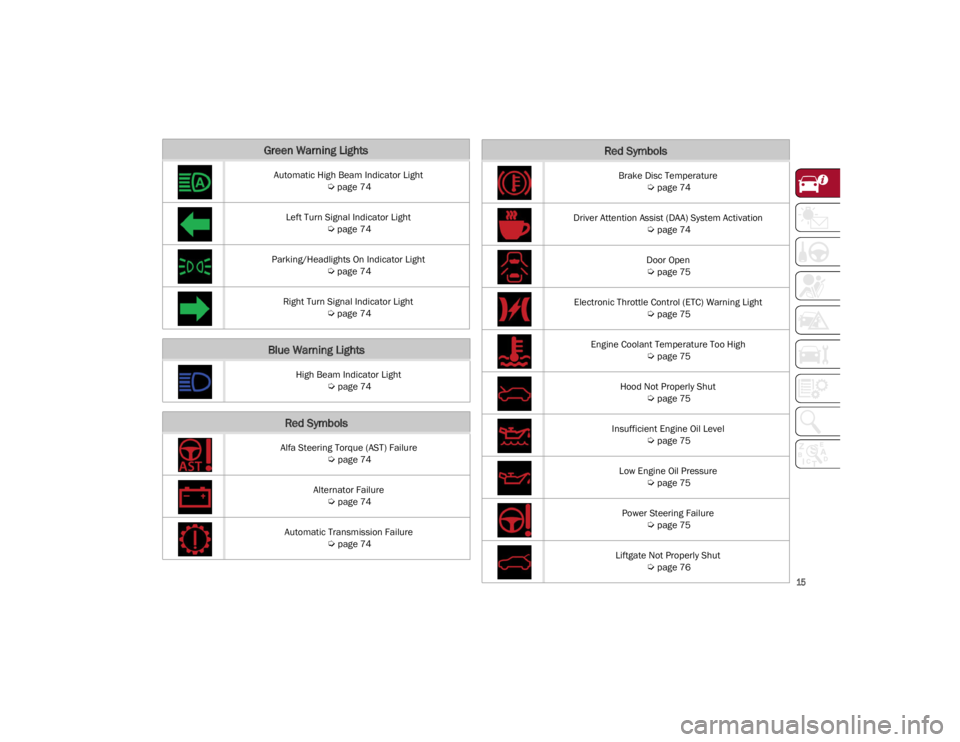
Green Warning Lights
Automatic High Beam Indicator Light
Ú
page 74
Left Turn Signal Indicator Light
Ú
page 74
Parking/Headlights On Indicator Light
Ú
page 74
Right Turn Signal Indicator Light
Ú
page 74
Blue Warning Lights
High Beam Indicator Light
Ú
page 74
Red Symbols
Alfa Steering Torque (AST) Failure
Ú
page 74
Alternator Failure
Ú
page 74
Automatic Transmission Failure
Ú
page 74
Brake Disc Temperature
Ú
page 74
Driver Attention Assist (DAA) System Activation
Ú
page 74
Door Open
Ú
page 75
Electronic Throttle Control (ETC) Warning Light
Ú
page 75
Engine Coolant Temperature Too High
Ú
page 75
Hood Not Properly Shut
Ú
page 75
Insufficient Engine Oil Level
Ú
page 75
Low Engine Oil Pressure
Ú
page 75
Power Steering Failure
Ú
page 75
Liftgate Not Properly Shut
Ú
page 76
Red Symbols
22_GU_OM_EN_USC_t.book Page 15
Page 18 of 256
SYMBOL GLOSSARY
16
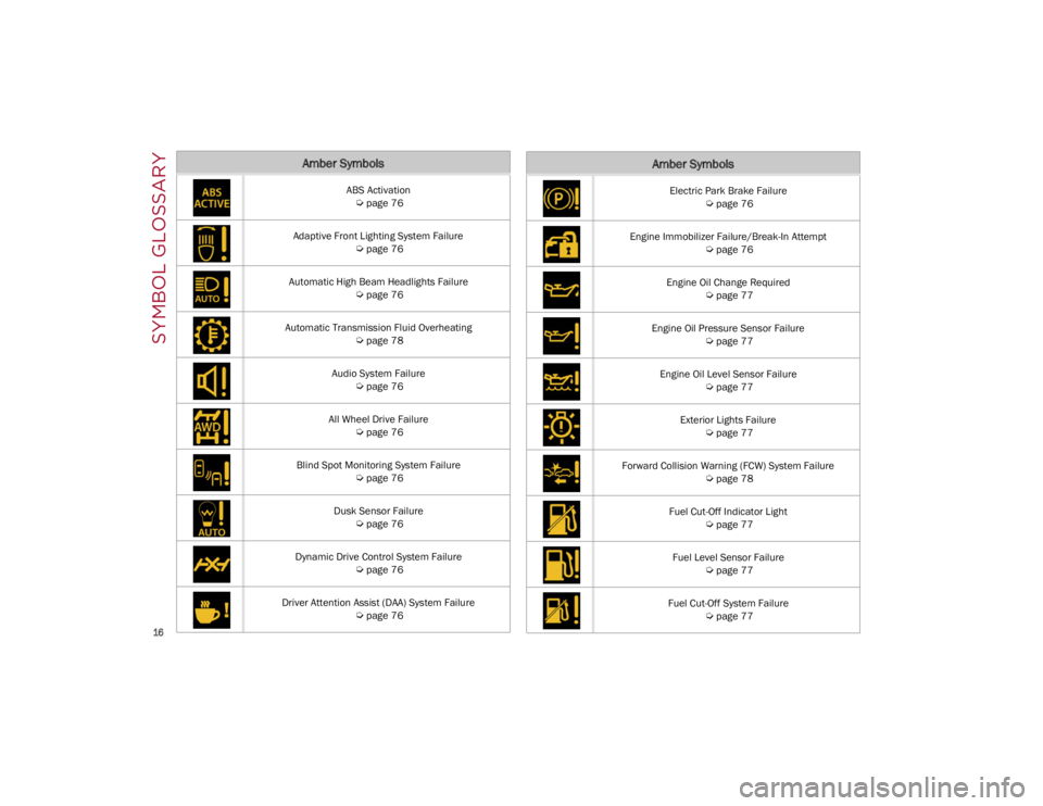
Amber Symbols
ABS Activation
Ú
page 76
Adaptive Front Lighting System Failure
Ú
page 76
Automatic High Beam Headlights Failure
Ú
page 76
Automatic Transmission Fluid Overheating
Ú
page 78
Audio System Failure
Ú
page 76
All Wheel Drive Failure
Ú
page 76
Blind Spot Monitoring System Failure
Ú
page 76
Dusk Sensor Failure
Ú
page 76
Dynamic Drive Control System Failure
Ú
page 76
Driver Attention Assist (DAA) System Failure
Ú
page 76
Electric Park Brake Failure
Ú
page 76
Engine Immobilizer Failure/Break-In Attempt
Ú
page 76
Engine Oil Change Required
Ú
page 77
Engine Oil Pressure Sensor Failure
Ú
page 77
Engine Oil Level Sensor Failure
Ú
page 77
Exterior Lights Failure
Ú
page 77
Forward Collision Warning (FCW) System Failure
Ú
page 78
Fuel Cut-Off Indicator Light
Ú
page 77
Fuel Level Sensor Failure
Ú
page 77
Fuel Cut-Off System Failure
Ú
page 77
Amber Symbols
22_GU_OM_EN_USC_t.book Page 16
Page 19 of 256
17
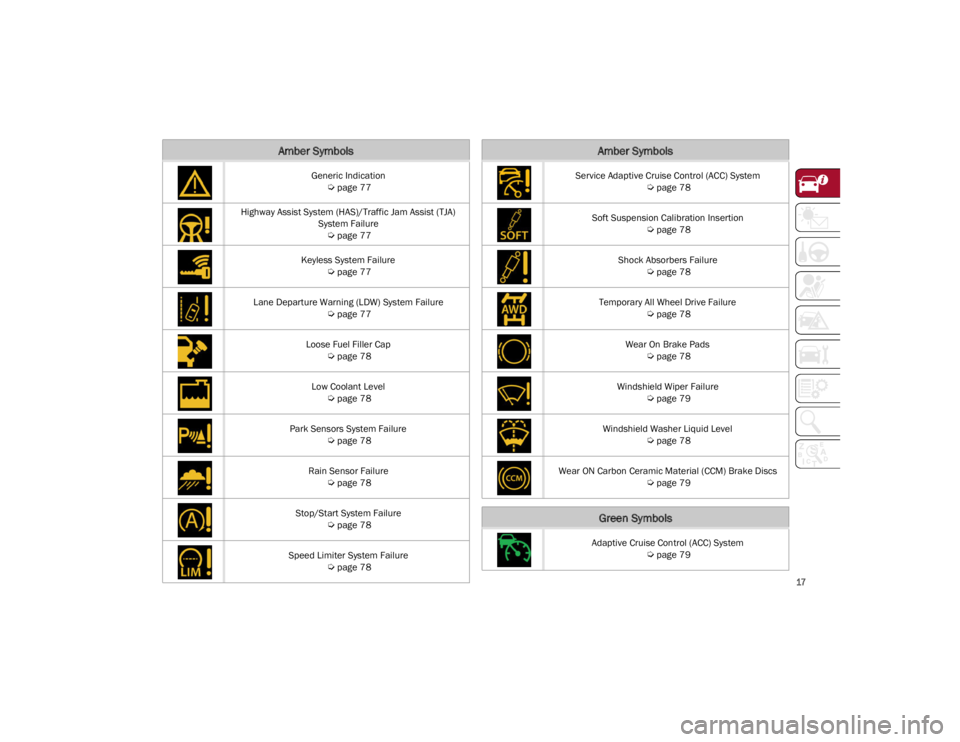
Generic Indication
Ú
page 77
Highway Assist System (HAS)/Traffic Jam Assist (TJA) System Failure
Ú
page 77
Keyless System Failure
Ú
page 77
Lane Departure Warning (LDW) System Failure
Ú
page 77
Loose Fuel Filler Cap
Ú
page 78
Low Coolant Level
Ú
page 78
Park Sensors System Failure
Ú
page 78
Rain Sensor Failure
Ú
page 78
Stop/Start System Failure
Ú
page 78
Speed Limiter System Failure
Ú
page 78
Amber Symbols
Service Adaptive Cruise Control (ACC) System
Ú
page 78
Soft Suspension Calibration Insertion
Ú
page 78
Shock Absorbers Failure
Ú
page 78
Temporary All Wheel Drive Failure
Ú
page 78
Wear On Brake Pads
Ú
page 78
Windshield Wiper Failure
Ú
page 79
Windshield Washer Liquid Level
Ú
page 78
Wear ON Carbon Ceramic Material (CCM) Brake Discs
Ú
page 79
Green Symbols
Adaptive Cruise Control (ACC) System
Ú
page 79
Amber Symbols
22_GU_OM_EN_USC_t.book Page 17
Page 41 of 256
39
UNIVERSAL GARAGE DOOR
OPENER (HOMELINK®)
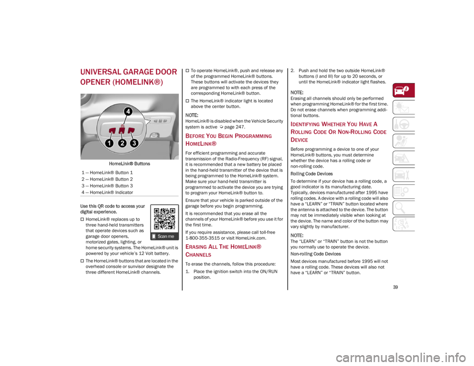
HomeLink® Buttons
Use this QR code to access your
digital experience.
HomeLink® replaces up to
three hand-held transmitters
that operate devices such as
garage door openers,
motorized gates, lighting, or
home security systems. The HomeLink® unit is
powered by your vehicle’s 12 Volt battery.
The HomeLink® buttons that are located in the
overhead console or sunvisor designate the
three different HomeLink® channels.
To operate HomeLink®, push and release any
of the programmed HomeLink® buttons.
These buttons will activate the devices they
are programmed to with each press of the
corresponding HomeLink® button.
The HomeLink® indicator light is located
above the center button.
NOTE:
HomeLink® is disabled when the Vehicle Security
system is active
Ú
page 247.
BEFORE YOU BEGIN PROGRAMMING
H
OMELINK®
For efficient programming and accurate
transmission of the Radio-Frequency (RF) signal,
it is recommended that a new battery be placed
in the hand-held transmitter of the device that is
being programmed to the HomeLink® system.
Make sure your hand-held transmitter is
programmed to activate the device you are trying
to program your HomeLink® button to.
Ensure that your vehicle is parked outside of the
garage before you begin programming.
It is recommended that you erase all the
channels of your HomeLink® before you use it for
the first time.
If you require assistance, please call toll-free
1-800-355-3515 or visit
HomeLink.com
.
ERASING ALL THE HOMELINK®
C
HANNELS
To erase the channels, follow this procedure:
1. Place the ignition switch into the ON/RUN
position. 2. Push and hold the two outside HomeLink®
buttons (I and III) for up to 20 seconds, or
until the HomeLink® indicator light flashes.
NOTE:
Erasing all channels should only be performed
when programming HomeLink® for the first time.
Do not erase channels when programming addi -
tional buttons.
IDENTIFYING WHETHER YOU HAVE A
R
OLLING CODE OR NON-ROLLING CODE
D
EVICE
Before programming a device to one of your
HomeLink® buttons, you must determine
whether the device has a rolling code or
non-rolling code.
Rolling Code Devices
To determine if your device has a rolling code, a
good indicator is its manufacturing date.
Typically, devices manufactured after 1995 have
rolling codes. A device with a rolling code will also
have a “LEARN” or “TRAIN” button located where
the antenna is attached to the device. The button
may not be immediately visible when looking at
the device. The name and color of the button may
vary slightly by manufacturer.
NOTE:
The “LEARN” or “TRAIN” button is not the button
you normally use to operate the device.
Non-rolling Code Devices
Most devices manufactured before 1995 will not
have a rolling code. These devices will also not
have a “LEARN” or “TRAIN” button.
1 — HomeLink® Button 1
2 — HomeLink® Button 2
3 — HomeLink® Button 3
4 — HomeLink® Indicator
22_GU_OM_EN_USC_t.book Page 39
Page 44 of 256
GETTING TO KNOW YOUR VEHICLE
42
If you have any problems, or require assistance,
please call toll-free 1-800-355-3515 or, on the
Internet at
HomeLink.com
for information or
assistance.
EXTERIOR LIGHTS
HEADLIGHT SWITCH
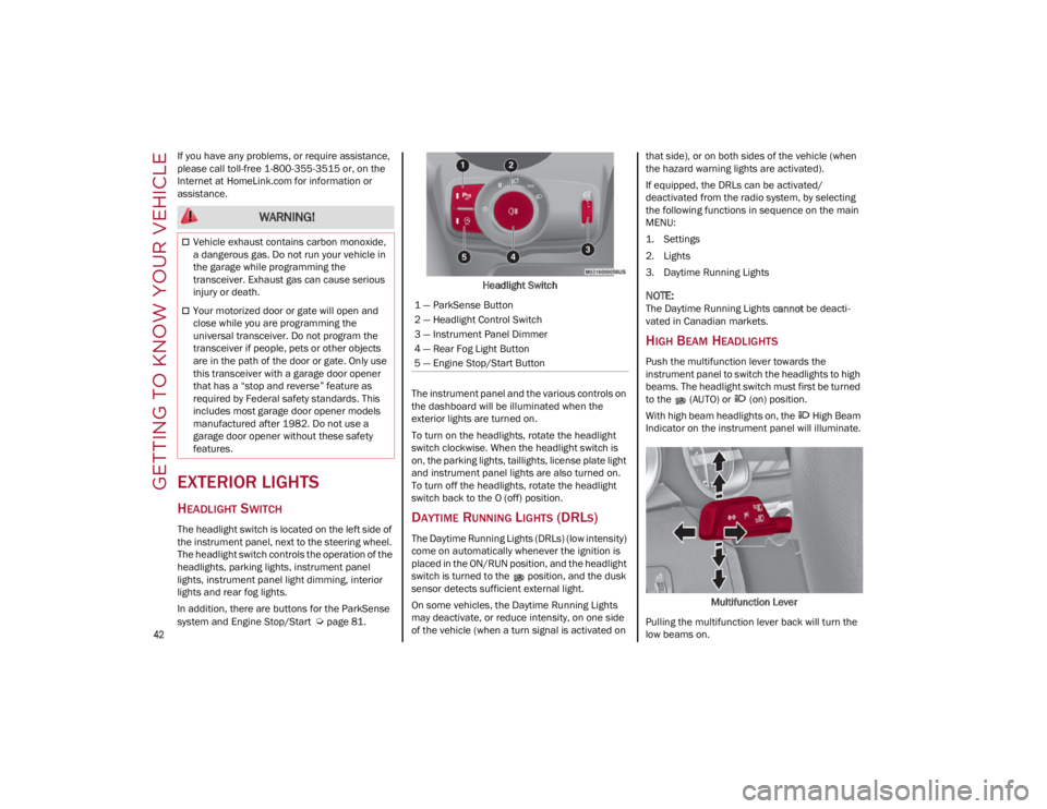
The headlight switch is located on the left side of
the instrument panel, next to the steering wheel.
The headlight switch controls the operation of the
headlights, parking lights, instrument panel
lights, instrument panel light dimming, interior
lights and rear fog lights.
In addition, there are buttons for the ParkSense
system and Engine Stop/Start
Ú
page 81. Headlight Switch
The instrument panel and the various controls on
the dashboard will be illuminated when the
exterior lights are turned on.
To turn on the headlights, rotate the headlight
switch clockwise. When the headlight switch is
on, the parking lights, taillights, license plate light
and instrument panel lights are also turned on.
To turn off the headlights, rotate the headlight
switch back to the O (off) position.
DAYTIME RUNNING LIGHTS (DRLS)
The Daytime Running Lights (DRLs) (low intensity)
come on automatically whenever the ignition is
placed in the ON/RUN position, and the headlight
switch is turned to the position, and the dusk
sensor detects sufficient external light.
On some vehicles, the Daytime Running Lights
may deactivate, or reduce intensity, on one side
of the vehicle (when a turn signal is activated on that side), or on both sides of the vehicle (when
the hazard warning lights are activated).
If equipped, the DRLs can be activated/
deactivated from the radio system, by selecting
the following functions in sequence on the main
MENU:
1. Settings
2. Lights
3. Daytime Running Lights
NOTE:
The Daytime Running Lights
cannot be deacti -
vated in Canadian markets.
HIGH BEAM HEADLIGHTS
Push the multifunction lever towards the
instrument panel to switch the headlights to high
beams. The headlight switch must first be turned
to the (AUTO) or (on) position.
With high beam headlights on, the High Beam
Indicator on the instrument panel will illuminate.
Multifunction Lever
Pulling the multifunction lever back will turn the
low beams on.
WARNING!
Vehicle exhaust contains carbon monoxide,
a dangerous gas. Do not run your vehicle in
the garage while programming the
transceiver. Exhaust gas can cause serious
injury or death.
Your motorized door or gate will open and
close while you are programming the
universal transceiver. Do not program the
transceiver if people, pets or other objects
are in the path of the door or gate. Only use
this transceiver with a garage door opener
that has a “stop and reverse” feature as
required by Federal safety standards. This
includes most garage door opener models
manufactured after 1982. Do not use a
garage door opener without these safety
features.1 — ParkSense Button
2 — Headlight Control Switch
3 — Instrument Panel Dimmer
4 — Rear Fog Light Button
5 — Engine Stop/Start Button
22_GU_OM_EN_USC_t.book Page 42
Page 45 of 256
43
AUTOMATIC HEADLIGHTS
This system automatically turns the headlights on
or off according to ambient light levels. To turn
the system on, rotate the headlight switch to the (AUTO) position.
NOTE:
The function can only operate with the ignition in
the ON/RUN position.
To turn the automatic headlights off, turn the
headlight switch out of the (AUTO) position.
FLASH-TO-PASS
You can signal another vehicle with your
headlights by lightly pulling the multifunction
lever toward you. This will cause the high beam
headlights to turn on, and remain on, until the
lever is released.
AUTOMATIC HIGH BEAM HEADLIGHTS —
I
F EQUIPPED
The Automatic High Beam Headlights system
provides increased forward lighting at night by
automating high beam control through the use of
a camera mounted on the windshield. This
camera detects vehicle specific light and
automatically switches from high beams to low
beams until the approaching vehicle is out of
view.
This function is enabled with the radio system,
and can only be activated with the light switch
turned to (auto).
If the high beam headlights are on, the blue icon/
warning light will illuminate in the instrument
panel. When the speed is higher than 25 mph (40 km/h)
and the function is active, the lights will turn off if
the multifunction lever is pushed again.
When the speed is lower than 15 mph (25 km/h)
and the function is active, the function switches
the high beam headlights off.
If the high beam headlights are operated quickly
again (pushing the multifunction lever towards
the instrument panel), the warning light/icon
will illuminate in the instrument panel, and the
high beam headlights will turn on constantly until
the speed exceeds 25 mph (40 km/h).
When the speed of 25 mph (40 km/h) is
exceeded again, the automatic functioning is
reactivated.
If the multifunction lever is pushed again with the
Automatic High Beam Headlights activated, the
Automatic High Beam Headlights function
deactivates.
To deactivate the automatic headlight function,
rotate the headlight switch to the position.
NOTE:
If the system recognizes heavy traffic areas,
the automatic functions remain disabled
independently of the vehicle’s speed.
The Automatic High Beam functionality may
also be influenced by:
• Reflections on road signs
• Dim headlights from oncoming traffic
• Poor weather conditions
• Presence of dirt or other obstructions on
the sensor
• Damage to the windshield
PARKING LIGHTS
To turn on the parking lights and instrument
panel lights, rotate the headlight switch clockwise
to the position. All of the parking lights will turn
on for eight minutes, and opening the door
activates an audible warning.
To leave only the lights on one side (right/left)
illuminated, move the multifunction lever
(located on the left side of the steering wheel) to
the side that you want to remain on. With the
parking lights on, the indicator light on the
instrument panel will illuminate.
To turn off the parking lights, rotate the headlight
switch back to the O (off) position.
HEADLIGHT OFF DELAY
To assist when exiting the vehicle, the “Headlight
Off Delay” feature will leave the headlights on for
up to 90 seconds. This delay is initiated when the
ignition is placed in the OFF position while the
headlight switch is on, and then the headlight
switch is cycled off. Headlight delay can be
canceled by either turning on the headlights or
side lights, or by placing the ignition in the ON
position.
The function can be activated from the radio
system by selecting the following functions in
sequence on the main menu:
1. Settings
2. Lights
3. Headlight Off Delay
22_GU_OM_EN_USC_t.book Page 43
Page 46 of 256
GETTING TO KNOW YOUR VEHICLE
44
REAR FOG LIGHTS
The rear fog light switch is located within the
headlight switch.
Push the button, located in the center of the
headlight switch, to turn the rear fog lights on/off.
The rear fog lights turn on only when the
headlights or parking lights are also turned on.
The lights can be turned off by pushing the
button again or by turning the headlight switch to
the O (off) position.
When the engine is stopped with the rear fog
lights on, they will be off the next time the engine
is started.
ADAPTIVE HEADLIGHT SYSTEM —
I
F EQUIPPED
This is a system combined with Xenon headlights
(Bi-Xenon 35 W headlamp, if equipped) which
directs the headlights horizontally, and contin -
uously and automatically adapts them to the driving
conditions around bends or when cornering.
The system directs the headlights to light up the
road in the best way, taking into account the
speed of the vehicle and the bend or corner
angle, as well as the speed at which the steering
wheel is turned.
The adaptive lights are automatically activated
when the vehicle is started.
TURN SIGNALS
Move the multifunction lever up or down to activate
the turn signals. The arrows on each side of the
instrument cluster flash to show proper operation.
The or turn signal will blink on the
instrument panel.
LANE CHANGE ASSIST
Lightly push the lever up or down once, without
moving beyond the detent, and the turn signal will
flash five times then automatically turn off.
To turn off the flashing before the end of the
cycle, move the lever in the opposite direction
until the first click (about half way).
INTERIOR LIGHTS
Courtesy lights are turned on when the front
doors are opened or when the dimmer control is
rotated to its farthest upward position. The glove
compartment light turns on automatically when
the glove compartment is opened and turn off
when it is closed. The door courtesy lights
illuminate when one of the front doors is opened,
and turn off when it is closed. The liftgate
courtesy lights turn on automatically when the
liftgate is opened and turn off when it is closed.
All of these lights turn on and off regardless of the
ignition status.
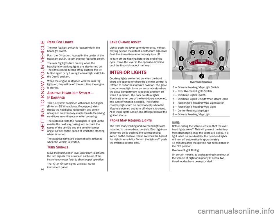
FRONT MAP READING LIGHTS
The front map/reading and overhead lights are
mounted in the overhead console. Each light can
be turned on by pushing the corresponding
switch on the console. These switches are backlit
for nighttime visibility. To turn the lights off, push
the switch a second time. Overhead Console
NOTE:
Before exiting the vehicle, ensure that the over
-
head lights are off. This will prevent the battery
from discharging once the doors are closed. If a
light is left on accidentally, the overhead lights
will turn off automatically approximately
15 minutes after the ignition has been placed in
the OFF position.
Overhead Light Timing
On certain models, to assist getting in and out of
the vehicle at night or in poorly-lit areas, two
timed modes have been provided.
1 — Driver’s Reading/Map Light Switch
2 — Rear Overhead Lights Switch
3 — Overhead Lights Switch
4 — Overhead Lights On/Off When Doors Open
5 — Passenger’s Reading/Map Light Switch
6 — Passenger’s Reading/Map Light
7 — Center Reading/Map Light
8 — Driver’s Reading/Map Light
22_GU_OM_EN_USC_t.book Page 44
Page 61 of 256
59
NOTE:
If the switch is released prior to full completion of
the operations described, the entire re-initializa-
tion procedure must be repeated from step 1.
7. Confirm express operations for the sunroof glass and sunshade are functional for
opening and closing operations.
SUNROOF MAINTENANCE
Use only a non-abrasive cleaner and a soft cloth
to clean the glass panel. Periodically check for
and clear out any debris that may have collected
in the tracks.
HOOD
OPENING THE HOOD
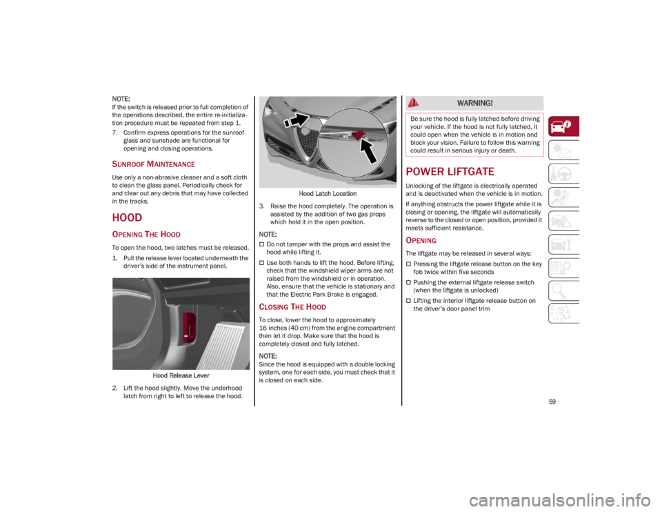
To open the hood, two latches must be released.
1. Pull the release lever located underneath the driver’s side of the instrument panel.
Hood Release Lever
2. Lift the hood slightly. Move the underhood latch from right to left to release the hood. Hood Latch Location
3. Raise the hood completely. The operation is assisted by the addition of two gas props
which hold it in the open position.
NOTE:
Do not tamper with the props and assist the
hood while lifting it.
Use both hands to lift the hood. Before lifting,
check that the windshield wiper arms are not
raised from the windshield or in operation.
Also, ensure that the vehicle is stationary and
that the Electric Park Brake is engaged.
CLOSING THE HOOD
To close, lower the hood to approximately
16 inches (40 cm) from the engine compartment
then let it drop. Make sure that the hood is
completely closed and fully latched.
NOTE:
Since the hood is equipped with a double locking
system, one for each side, you must check that it
is closed on each side.
POWER LIFTGATE
Unlocking of the liftgate is electrically operated
and is deactivated when the vehicle is in motion.
If anything obstructs the power liftgate while it is
closing or opening, the liftgate will automatically
reverse to the closed or open position, provided it
meets sufficient resistance.
OPENING
The liftgate may be released in several ways:
Pressing the liftgate release button on the key
fob twice within five seconds
Pushing the external liftgate release switch
(when the liftgate is unlocked)
Lifting the interior liftgate release button on
the driver’s door panel trim
WARNING!
Be sure the hood is fully latched before driving
your vehicle. If the hood is not fully latched, it
could open when the vehicle is in motion and
block your vision. Failure to follow this warning
could result in serious injury or death.
22_GU_OM_EN_USC_t.book Page 59