roof ALFA ROMEO STELVIO 2022 Owners Manual
[x] Cancel search | Manufacturer: ALFA ROMEO, Model Year: 2022, Model line: STELVIO, Model: ALFA ROMEO STELVIO 2022Pages: 256, PDF Size: 10.17 MB
Page 11 of 256
9
EXTERIOR LIGHTS ...................................42
Headlight Switch .................................... 42
Daytime Running Lights (DRLs) ............ 42
High Beam Headlights .......................... 42
Automatic Headlights ............................ 43
Flash-To-Pass ......................................... 43
Automatic High Beam Headlights —
If Equipped ............................................. 43 Parking Lights ....................................... 43
Headlight Off Delay ................................ 43
Rear Fog Lights ...................................... 44
Adaptive Headlight System —
If Equipped ............................................. 44 Turn Signals ........................................... 44
Lane Change Assist ............................... 44
INTERIOR LIGHTS ....................................44
Front Map Reading Lights ..................... 44
Interior Ambient Lighting ...................... 45
Rear Overhead Light ............................. 45
Instrument Panel Dimmer Control ........ 45
WINDSHIELD WIPERS AND WASHERS....46
Windshield Wiper Operation ................. 46
Rain Sensing Wipers.............................. 47
Rear Window Wiper/Washer................. 47
Headlamp Washers — If Equipped ....... 47
CLIMATE CONTROLS ...............................48
Automatic Dual-Zone Climate Control
System .................................................... 48
INTERIOR STORAGE AND EQUIPMENT ... 54
Glove Compartment ...............................54
Center Console .......................................54
Rear Armrest ..........................................54
Power Outlets .........................................54
Cigar Lighter And Ash Tray —
If Equipped .............................................55 Wireless Charging Pad — If Equipped ...55
POWER WINDOWS................................... 56
Power Window Controls .........................56
Auto-Up Feature With Anti-Pinch
Protection ............................................... 57 Power Window System Initialization .....57
Wind Buffeting .......................................57
POWER SUNROOF — IF EQUIPPED ........ 57
Power Sunroof ........................................ 57
Opening And Closing The Sunroof ........58
Venting Sunroof......................................58
Sunshade Operation ..............................58
Pinch Protect Feature ............................58
Re-Initialization Procedure ....................58
Sunroof Maintenance ............................59
HOOD ...................................................... 59
Opening The Hood ................................. 59
Closing The Hood ...................................59
POWER LIFTGATE ................................... 59
Opening...................................................59
Closing ....................................................60
Liftgate Initialization ..............................61
Cargo Area Features ..............................62
GETTING TO KNOW YOUR
INSTRUMENT PANEL
INSTRUMENT PANEL FEATURES ........... 64
Instrument Cluster ............................... 64
Instrument Cluster Descriptions .......... 65
INSTRUMENT CLUSTER DISPLAY ........... 66
Instrument Cluster Display
Description ............................................. 66 Reconfigurable Instrument Cluster
Display .................................................... 66 Reconfigurable Display Items ............... 66
Customer Programmable Settings ....... 69
WARNING LIGHTS AND MESSAGES
ON THE INSTRUMENT PANEL ................. 70
Red Warning Lights ............................... 70
Amber Warning Lights ........................... 72
Green Indicator Lights........................... 74
Blue Indicator Lights ............................. 74
Red Symbols .......................................... 74
Amber Symbols ...................................... 76
Green Symbols ...................................... 79
Blue Symbols ......................................... 79
ONBOARD DIAGNOSTIC SYSTEM ............ 79
Onboard Diagnostic System (OBD II)
Cybersecurity ......................................... 79
EMISSIONS INSPECTION AND
MAINTENANCE PROGRAMS .................... 80
22_GU_OM_EN_USC_t.book Page 9
Page 25 of 256
23
REMOTE START —
IF EQUIPPED
This system uses the key fob to start the
engine conveniently from outside the
vehicle while still maintaining security.
NOTE:
Obstructions between the vehicle and key fob
may reduce this range
Ú
page 247.
HOW TO USE REMOTE START
Push the Remote Start button on the key fob
twice within five seconds. The vehicle doors will
lock, the turn signals will flash twice, and the horn
will chirp twice. Pushing the Remote Start button
a third time shuts the engine off.
NOTE:
With Remote Start, the engine will only run for
15 minutes.
Remote Start can only be used twice.
If an engine fault is present or fuel level is low,
the vehicle will start and then shut down in 10
seconds.
The parking lights will turn on and remain on
during Remote Start mode.
For security, power window and power sunroof
(if equipped) operation is disabled when the
vehicle is in the Remote Start mode.
The ignition must be placed in the ACC position
before the Remote Start sequence can be
repeated for a third cycle.
All of the following conditions must be met before
the engine will remote start:
Gear selector in PARK
Doors closed
Hood closed
Liftgate closed
Hazard switch off
Brake switch inactive (brake pedal not
pressed)
Battery at an acceptable charge level
PANIC button not pushed
System not disabled from previous Remote
Start event
Vehicle Security system indicator flashing
Ignition in OFF position
Fuel level meets minimum requirement
Vehicle Security system is not signaling an
intrusion
Malfunction Indicator Light (MIL) is not
illuminated
TO EXIT REMOTE START MODE
To drive the vehicle after starting the Remote
Start system, either push and release the unlock
button on the key fob to unlock the doors, or
unlock the vehicle using Passive Entry via the
door handles, and disarm the Vehicle Security
system (if equipped). Then, prior to the end of the
15 minute cycle, push and release the START/
STOP ignition button while pressing the brake
pedal.
The Remote Start system will turn the engine off
if the Remote Start button is pushed again, or if
the engine is allowed to run for the entire
15 minute cycle.
REMOTE START COMFORT SYSTEMS —
I
F EQUIPPED
When Remote Start is activated, the heated
steering wheel and front heated seat features will
automatically activate when ambient
temperature is less than 39°F (4°C). These
features will stay on through the duration of
Remote Start.
NOTE:
This feature can be activated through the radio
system. Refer to the Information and Entertain -
ment System Owner’s Manual Supplement for
further information.
WARNING!
Do not start or run an engine in a closed
garage or confined area. Exhaust gas
contains Carbon Monoxide (CO) which is
odorless and colorless. Carbon Monoxide is
poisonous and can cause serious injury or
death when inhaled.
Keep key fobs away from children. Operation
of the Remote Start system, windows, door
locks or other controls could cause serious
injury or death.
22_GU_OM_EN_USC_t.book Page 23
Page 38 of 256
GETTING TO KNOW YOUR VEHICLE
36
Front Head Restraint
NOTE:
To allow for maximum visibility for the driver, if a
seat is not occupied by a passenger, the head
restraint can be lowered to the fully lowered posi-
tion.
Rear Head Restraint Adjustments
The height of the outboard head restraints can be
adjusted. The head restraint of the center seat, if
equipped, cannot be adjusted, only removed.
For upward adjustment, pull upward on the head
restraint until it clicks into place.
For downward adjustment, push in the
adjustment button and lower the head restraint
at the same time to the desired height.
Rear Head Restraint
NOTE:
To allow for maximum visibility for the driver, if a
seat is not occupied by a passenger, the head
restraint should be lowered to the fully lowered
position.
Head Restraint Removal
To remove the head restraints, proceed as
follows:
1. Recline the seatback to allow clearance of the head restraint from the vehicle’s roof. 2. Raise the head restraints to their maximum
height.
3. Push the adjustment button and the release button at the side of the two supports at the
same time.
4. Pull upward on the head restraint to fully remove it.
To reinstall the head restraints, proceed as
follows:
1. Hold down both the adjustment button and release button while placing the head
restraint posts into the holes.
2. Then, reposition the head restraint to the appropriate height for the passengers.
3. Replace the seatback to the appropriate position for passengers.
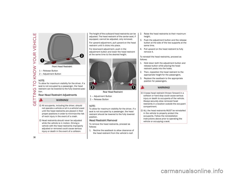
1 — Release Button
2 — Adjustment Button
WARNING!
All occupants, including the driver, should
not operate a vehicle or sit in a vehicle’s seat
until the head restraints are placed in their
proper positions in order to minimize the risk
of neck injury in the event of a crash.
Head restraints should never be adjusted
while the vehicle is in motion. Driving a
vehicle with the head restraints improperly
adjusted or removed could cause serious
injury or death in the event of a collision.
1 — Adjustment Button
2 — Release Button
WARNING!
A loose head restraint thrown forward in a
collision or hard stop could cause serious
injury or death to occupants of the vehicle.
Always securely stow removed head
restraints in a location outside the occupant
compartment.
ALL the head restraints MUST be reinstalled
in the vehicle to properly protect the
occupants. Follow the reinstallation
instructions above prior to operating the
vehicle or occupying a seat.
22_GU_OM_EN_USC_t.book Page 36
Page 59 of 256
57
AUTO-UP FEATURE WITH ANTI-PINCH
P
ROTECTION
The vehicle is equipped with an anti-pinch safety
device for closing the windows.
If the safety system senses any obstacle while the
window is closing, it will stop the window’s
movement and reverse it, depending on its
position.
This device is also useful if the windows are
activated accidentally by children inside the
vehicle.
The anti-pinch safety function is activated both
during the manual and the automatic operation
of the window.
When the anti-pinch system is activated, the
window closing is immediately interrupted. Then
the window closing is automatically reversed and
the window lowers by about 8 inches (20 cm) in
relation to the first stop position. The window
cannot be operated during this time.
NOTE:
In the event of an error, or if the anti-pinch protec -
tion is activated three consecutive times, the
automatic closing operation of the window will be
deactivated. In order to restore the correct opera -
tion of the system, the window must be lowered.
POWER WINDOW SYSTEM INITIALIZATION
If power supply is interrupted, the electric window
automatic operation must be reinitialized.
To perform the initialization procedure, which
must be done on each door with the doors closed,
manually fully close the window to be initialized.
WIND BUFFETING
Wind buffeting can be described as the
perception of pressure on the ears or a
helicopter-type sound in the ears. Your vehicle
may exhibit wind buffeting with the windows
down, or the sunroof (if equipped) in certain open
or partially open positions. This is a normal
occurrence and can be minimized. If the buffeting
occurs with the rear windows open, open the front
and rear windows together to minimize the
buffeting. If the buffeting occurs with the sunroof
open, adjust the sunroof opening to minimize the
buffeting or open any window.
POWER SUNROOF — IF
EQUIPPED
POWER SUNROOF
The power sunroof consists of a single glass
panel and is fitted with a power sunshade the full
length of the panel.
Operation of the sunroof is only possible with the
ignition in the ACC or ON/RUN position
Ú
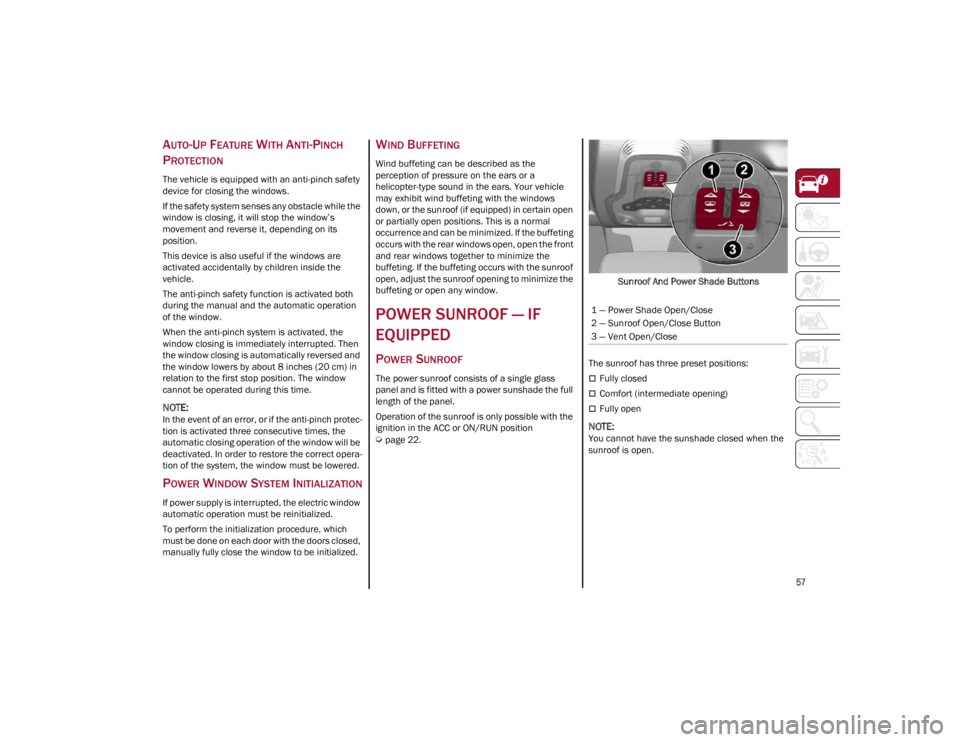
page 22. Sunroof And Power Shade Buttons
The sunroof has three preset positions:
Fully closed
Comfort (intermediate opening)
Fully open
NOTE:
You cannot have the sunshade closed when the
sunroof is open. 1 — Power Shade Open/Close
2 — Sunroof Open/Close Button
3 — Vent Open/Close
22_GU_OM_EN_USC_t.book Page 57
Page 60 of 256
GETTING TO KNOW YOUR VEHICLE
58
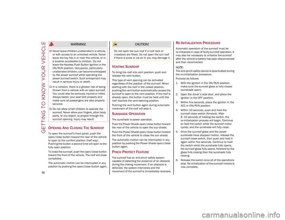
OPENING AND CLOSING THE SUNROOF
To open the sunroof’s front panel, push the
open/close button toward the rear of the vehicle
to open to the comfort position (half way).
Pushing the button a second time will open to the
fully open position.
To close the sunroof, push the open/close button
toward the front of the vehicle. The roof will close
completely.
The automatic motion can be interrupted in any
position by pushing the open/close button again.
VENTING SUNROOF
To bring the roof into vent position, push and
release the vent button.
This type of vent opening can be activated
regardless of the position of the sunroof. When
starting with the roof in the closed position,
pushing the vent button automatically causes the
sunroof to open to the vent position. If the roof is
already open, the button must be held until the
roof reaches the vent-opening position.
Pushing the vent button again during automatic
movement of the roof will stop it.
SUNSHADE OPERATION
The sunshade is power operated.
Push the Power Shade open/close button toward
the rear of the vehicle to open the sun shade.
Push the Power Shade open/close button toward
the front of the vehicle to close the sun shade.
The automatic motion can be interrupted in any
position by pushing the Power Shade open/close
button again.
PINCH PROTECT FEATURE
The sunroof has an anti-pinch safety system
capable of detecting the presence of an obstacle
during the closing movement. If an obstacle is
detected, the system intervenes and the
movement of the sunroof is immediately reversed.
RE-INITIALIZATION PROCEDURE
Automatic operation of the sunroof must be
re-initialized in case of faulty sunroof operation. It
may also be necessary to initialize the sunroof
after the vehicle’s battery has been disconnected
and then reconnected.
NOTE:
The anti-pinch safety device is deactivated during
the re-initialization procedure.
Proceed as follows:
1. With the ignition in the ON/RUN position, make sure the sunroof glass is fully closed
(sunshade open).
2. Open the driver’s side door, and place the ignition in the OFF position.
3. Within five seconds, place the ignition in the ACC or ON/RUN position.
4. Within 10 seconds, push and hold the sunroof close switch (forward). After
8 -10 seconds of holding the switch, the
re-initialization process will begin. Continue
to hold the switch while the sunroof motor
cycles, and the sunshade will fully close.
5. Once the sunroof glass and the power sunshade have stopped motion, release the
sunroof close switch, then push and hold it
again within five seconds. Continue to hold
the switch while the sunshade fully opens,
the sunroof glass fully opens, followed by the
glass fully closing then the sunshade fully
closing.
6. Release the switch once all of the operations stop. Re-initialization of the sunroof motors is
now complete.
WARNING!
Never leave children unattended in a vehicle,
or with access to an unlocked vehicle. Never
leave the key fob in or near the vehicle, or in
a location accessible to children. Do not
leave the Keyless Push Button Ignition in the
ON/RUN position. Occupants, particularly
unattended children, can become entrapped
by the power sunroof while operating the
power sunroof switch. Such entrapment may
result in serious injury or death.
In a collision, there is a greater risk of being
thrown from a vehicle with an open sunroof.
You could also be seriously injured or killed.
Always fasten your seat belt properly and
make sure all passengers are also properly
secured.
Do not allow small children to operate the
sunroof. Never allow your fingers, other body
parts, or any object, to project through the
sunroof opening. Injury may result.
CAUTION!
Do not open the sun roof if a roof rack or
crossbars are fitted. Do not open the sun roof
if there is snow or ice on it: you may damage it.
22_GU_OM_EN_USC_t.book Page 58
Page 61 of 256
59
NOTE:
If the switch is released prior to full completion of
the operations described, the entire re-initializa-
tion procedure must be repeated from step 1.
7. Confirm express operations for the sunroof glass and sunshade are functional for
opening and closing operations.
SUNROOF MAINTENANCE
Use only a non-abrasive cleaner and a soft cloth
to clean the glass panel. Periodically check for
and clear out any debris that may have collected
in the tracks.
HOOD
OPENING THE HOOD
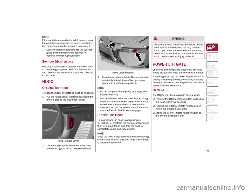
To open the hood, two latches must be released.
1. Pull the release lever located underneath the driver’s side of the instrument panel.
Hood Release Lever
2. Lift the hood slightly. Move the underhood latch from right to left to release the hood. Hood Latch Location
3. Raise the hood completely. The operation is assisted by the addition of two gas props
which hold it in the open position.
NOTE:
Do not tamper with the props and assist the
hood while lifting it.
Use both hands to lift the hood. Before lifting,
check that the windshield wiper arms are not
raised from the windshield or in operation.
Also, ensure that the vehicle is stationary and
that the Electric Park Brake is engaged.
CLOSING THE HOOD
To close, lower the hood to approximately
16 inches (40 cm) from the engine compartment
then let it drop. Make sure that the hood is
completely closed and fully latched.
NOTE:
Since the hood is equipped with a double locking
system, one for each side, you must check that it
is closed on each side.
POWER LIFTGATE
Unlocking of the liftgate is electrically operated
and is deactivated when the vehicle is in motion.
If anything obstructs the power liftgate while it is
closing or opening, the liftgate will automatically
reverse to the closed or open position, provided it
meets sufficient resistance.
OPENING
The liftgate may be released in several ways:
Pressing the liftgate release button on the key
fob twice within five seconds
Pushing the external liftgate release switch
(when the liftgate is unlocked)
Lifting the interior liftgate release button on
the driver’s door panel trim
WARNING!
Be sure the hood is fully latched before driving
your vehicle. If the hood is not fully latched, it
could open when the vehicle is in motion and
block your vision. Failure to follow this warning
could result in serious injury or death.
22_GU_OM_EN_USC_t.book Page 59
Page 120 of 256
STARTING AND OPERATING
118
(Continued)
TURNING LANE DEPARTURE WARNING
O
N OR OFF
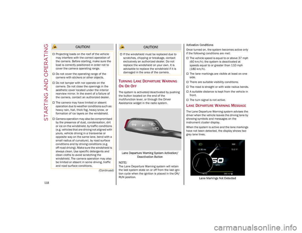
The system is activated/deactivated by pushing
the button located on the end of the
multifunction lever, or through the Driver
Assistance widget in the radio system.
Lane Departure Warning System Activation/ Deactivation Button
NOTE:
The Lane Departure Warning system will retain
the last system state on or off from the last igni -
tion cycle when the ignition is placed in the ON/
RUN position. Activation Conditions
Once turned on, the system becomes active only
if the following conditions are met:
The vehicle speed is equal to or above 37 mph
(60 km/h); the system is deactivated at
speeds equal to or greater than 110 mph
(180 km/h).
The lane markings are visible at least on one
side.
There are suitable visibility conditions.
The road is straight or with wide radius bends.
A suitable distance is kept from the vehicle in
front.
The turn signal is not active.
LANE DEPARTURE WARNING MESSAGE
The Lane Departure Warning system advises the
driver when the vehicle leaves the driving lane by
showing symbols and messages on the
instrument cluster display.
When the system is active and the lane markings
have not been detected, the display shows two
grey lane lines.
Lane Markings Not Detected
CAUTION!
Projecting loads on the roof of the vehicle
may interfere with the correct operation of
the camera. Before starting, make sure the
load is correctly positioned in order not to
cover the camera operating range.
Do not cover the operating range of the
camera with stickers or other objects.
Do not tamper with nor operate on the
camera. Do not close the openings in the
aesthetic cover located under the interior
rearview mirror. In the event of a failure of
the camera, contact an authorized dealer.
The camera may have limited or absent
operation due to weather conditions such as:
heavy rain, hail, thick fog, heavy snow, or
formation of ice layers on the windshield.
Camera operation may also be compromised
by the presence of dust, condensation, dirt
or ice on the windshield, by traffic conditions
(e.g. vehicles that are driving not aligned with
yours, vehicle driving in a transverse or
opposite way on the same lane, bend with a
small radius of curvature), by road surface
conditions and by driving conditions (e.g.
off-road driving). Make sure the windshield is
always clean. Use specific detergents and
clean cloths to avoid scratching the
windshield. The camera operation may also
be limited or absent in some driving, traffic
and road surface conditions.
If the windshield must be replaced due to
scratches, chipping or breakage, contact
exclusively an authorized dealer. Do not
replace the windshield on your own. It is
advisable to replace the windshield if it is
damaged in the area of the camera.
CAUTION!
22_GU_OM_EN_USC_t.book Page 118
Page 124 of 256
STARTING AND OPERATING
122
(Continued)
After 15 seconds with the hands removed from
the steering wheel, the LKA system will be
deactivated and a dedicated message will be
shown on the instrument cluster display. A short
acoustic signal will sound in this case.
In any of the situations above where the hands
are removed from the steering wheel for more
than 6 seconds, it is necessary to reposition the
hands on the steering wheel.
Changing The System Sensitivity
The system's sensitivity can be set through the
radio system in the Driver Assistance menu.
Select “Lane Keep Assist - Settings” and then
“Keeping sensitivity”. Sensitivity “Early” or “Late”
can be selected.
Changing The System Strength
The system’s strength can be set through the
radio system in the Driver Assistance menu.
Select “Lane Keep Assist - Settings” and then
“Strength”. Strength “Low” or “High” can be
selected.
Limited Operation Warning
If a message appears on the display, a condition
limiting the LKA system operation may have
occurred. This could be an obstruction of the
camera view, or a fault in the system.
If an obstruction is detected, clean the area of the
windshield by the interior rearview mirror.
Although the vehicle can still be driven in normal
conditions, the system may not function properly.
When the conditions limiting the system are
corrected, it will go back to normal operation.
Should a fault persist, contact an authorized
dealer.
System Failure Signaling
If the system turns off and appears on the
display, it means that there is a system fault.
In this case, it is still possible to drive the vehicle,
but you are advised to contact an authorized
dealer as soon as possible.
REAR BACK UP CAMERA /
DYNAMIC GRIDLINES
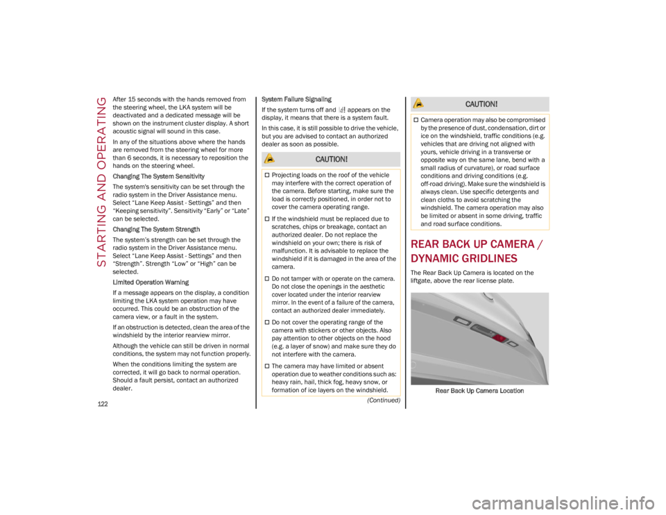
The Rear Back Up Camera is located on the
liftgate, above the rear license plate.
Rear Back Up Camera Location
CAUTION!
Projecting loads on the roof of the vehicle
may interfere with the correct operation of
the camera. Before starting, make sure the
load is correctly positioned, in order not to
cover the camera operating range.
If the windshield must be replaced due to
scratches, chips or breakage, contact an
authorized dealer. Do not replace the
windshield on your own; there is risk of
malfunction. It is advisable to replace the
windshield if it is damaged in the area of the
camera.
Do not tamper with or operate on the camera.
Do not close the openings in the aesthetic
cover located under the interior rearview
mirror. In the event of a failure of the camera,
contact an authorized dealer immediately.
Do not cover the operating range of the
camera with stickers or other objects. Also
pay attention to other objects on the hood
(e.g. a layer of snow) and make sure they do
not interfere with the camera.
The camera may have limited or absent
operation due to weather conditions such as:
heavy rain, hail, thick fog, heavy snow, or
formation of ice layers on the windshield.
Camera operation may also be compromised
by the presence of dust, condensation, dirt or
ice on the windshield, traffic conditions (e.g.
vehicles that are driving not aligned with
yours, vehicle driving in a transverse or
opposite way on the same lane, bend with a
small radius of curvature), or road surface
conditions and driving conditions (e.g.
off-road driving). Make sure the windshield is
always clean. Use specific detergents and
clean cloths to avoid scratching the
windshield. The camera operation may also
be limited or absent in some driving, traffic
and road surface conditions.
CAUTION!
22_GU_OM_EN_USC_t.book Page 122
Page 162 of 256
SAFETY
160
(Continued)
SABICs may help reduce the risk of head and
other injuries to front and rear seat outboard
occupants in certain side impacts, in addition to
the injury reduction potential provided by the seat
belts and body structure.
The SABIC deploys downward, covering the side
windows. An inflating SABIC pushes the outside
edge of the headliner out of the way and covers
the window. The SABICs inflate with enough force
to injure occupants if they are not belted and
seated properly, or if items are positioned in the
area where the SABICs inflate. Children are at an
even greater risk of injury from a deploying air
bag.
The SABICs may help reduce the risk of partial or
complete ejection of vehicle occupants through
side windows in certain side impact events.
Side Impacts
The Side Air Bags are designed to activate in
certain side impacts. The Occupant Restraint
Controller (ORC) determines whether the
deployment of the Side Air Bags in a particular
impact event is appropriate, based on the
severity and type of collision. The side impact
sensors aid the ORC in determining the
appropriate response to impact events. The
system is calibrated to deploy the Side Air Bags
on the impact side of the vehicle during impacts
that require Side Air Bag occupant protection. In
side impacts, the Side Air Bags deploy
independently; a left side impact deploys the left
Side Air Bags only and a right-side impact deploys
the right Side Air Bags only. Vehicle damage by
itself is not a good indicator of whether or not
Side Air Bags should have deployed.
The Side Air Bags will not deploy in all side
collisions, including some collisions at certain
angles, or some side collisions that do not impact
the area of the passenger compartment. The Side
Air Bags may deploy during angled or offset
frontal collisions where the front air bags deploy.
Side Air Bags are a supplement to the seat belt
restraint system. Side Air Bags deploy in less time
than it takes to blink your eyes.
NOTE:
Air bag covers may not be obvious in the interior
trim, but they will open during air bag deploy
-
ment.
WARNING!
Do not mount equipment, or stack luggage or
other cargo up high enough to block the
deployment of the SABICs. The trim covering
above the side windows where the SABIC and
its deployment path are located should
remain free from any obstructions.
In order for the SABICs to work as intended,
do not install any accessory items in your
vehicle which could alter the roof. Do not add
an aftermarket sunroof to your vehicle. Do
not add roof racks that require permanent
attachments (bolts or screws) for installation
on the vehicle roof. Do not drill into the roof
of the vehicle for any reason.
WARNING!
Occupants, including children, who are up
against or very close to Side Air Bags can be
seriously injured or killed. Occupants,
including children, should never lean on or
sleep against the door, side windows, or area
where the side air bags inflate, even if they
are in an infant or child restraint.
Seat belts (and child restraints where
appropriate) are necessary for your
protection in all collisions. They also help
keep you in position, away from an inflating
Side Air Bag. To get the best protection from
the Side Air Bags, occupants must wear their
seat belts properly and sit upright with their
backs against the seats. Children must be
properly restrained in a child restraint or
booster seat that is appropriate for the size
of the child.
WARNING!
Side Air Bags need room to inflate. Do not
lean against the door or window. Sit upright
in the center of the seat.
Being too close to the Side Air Bags during
deployment could cause you to be severely
injured or killed.
Relying on the Side Air Bags alone could lead
to more severe injuries in a collision. The
Side Air Bags work with your seat belt to
restrain you properly. In some collisions, Side
Air Bags won’t deploy at all. Always wear your
seat belt even though you have Side Air
Bags.
WARNING!
22_GU_OM_EN_USC_t.book Page 160
Page 240 of 256
TECHNICAL SPECIFICATIONS
238
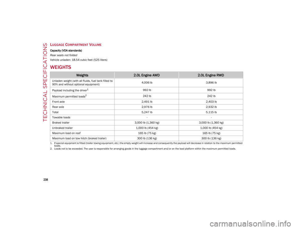
LUGGAGE COMPARTMENT VOLUME
Capacity (VDA standards)
Rear seats not folded
Vehicle unladen: 18.54 cubic feet (525 liters)
WEIGHTS
Weights2.0L Engine AWD2.0L Engine RWD
Unladen weight (with all fluids, fuel tank filled to
90% and without optional equipment) 4,006 lb
3,896 lb
Payload including the driver
1
1. If special equipment is fitted (trailer towing equipment, etc.) the empty weight will increase and consequently the payload will decrease in relation to the maximum permitted loads.
992 lb 992 lb
Maximum permitted loads
2
2. Loads not to be exceeded. The user is responsible for arranging goods in the luggage compartment and/or on the load platform within the maximum permitted loads.
242 lb 242 lb
Front axle 2,491 lb2,403 lb
Rear axle 2,976 lb2,932 lb
Total 5,247 lb5,115 lb
Towable loads --
Braked trailer 3,000 lb (1,360 kg)3,000 lb (1,360 kg)
Unbraked trailer 1,000 lb (454 kg)1,000 lb (454 kg)
Maximum load on roof 165 lb (75 kg)165 lb (75 kg)
Maximum load on tow hitch (braked trailer) 300 lb (136 kg)300 lb (136 kg)
22_GU_OM_EN_USC_t.book Page 238