tire type ALFA ROMEO STELVIO 2022 Owners Manual
[x] Cancel search | Manufacturer: ALFA ROMEO, Model Year: 2022, Model line: STELVIO, Model: ALFA ROMEO STELVIO 2022Pages: 256, PDF Size: 10.17 MB
Page 14 of 256
12
JUMP STARTING ................................... 184
Remote Battery Connection Posts......184
Jump Starting Procedure.....................186
Bump Starting ..................................... 187
ENGINE OVERHEATING ......................... 187 MANUAL PARK RELEASE ...................... 188TOWING A DISABLED VEHICLE ............ 188
Four-Wheel Drive (AWD) Models .........189
TOW EYES ............................................. 189ENHANCED ACCIDENT RESPONSE
SYSTEM (EARS) .................................... 190EVENT DATA RECORDER (EDR) ............ 190
SERVICING AND MAINTENANCE
SCHEDULED SERVICING ....................... 191
Periodic Checks ...................................191
Heavy Usage Of The Vehicle ...............191
Maintenance Plan — 2.0L Engine .......192
Maintenance Plan — 2.9L Engine .......194
ENGINE COMPARTMENT....................... 196
Checking Levels — 2.0L Engine .......... 196
Checking Levels — 2.9L Engine .......... 197
Engine Oil ............................................. 197
Engine Coolant Fluid............................198
Washer Fluid For Windshield/
Headlights ............................................ 198 Brake Fluid ...........................................199
Automatic Transmission Activation
System Oil ............................................ 199 Useful Advice For Extending The
Life Of Your Battery .............................. 199 Battery ..................................................199
Pressure Washing ................................ 200
BATTERY RECHARGING ......................... 200
Important Notes .................................. 200
VEHICLE MAINTENANCE ........................ 201
Engine Oil ............................................. 201
Engine Oil Filter ................................... 201
Engine Air Cleaner Filter ..................... 201
Air Conditioning System
Maintenance........................................ 201 Lubricating Moving Parts Of The
Bodywork ............................................. 202 Windshield Wiper................................. 202
Exhaust System ................................... 204
Cooling System .................................... 204
Braking System.................................... 205
Automatic Transmission ..................... 206
Replacing The Battery ......................... 206
Fuses .................................................... 206
Bulb Replacement ............................... 212
TIRES ..................................................... 216
Tire Safety Information ....................... 216
Tires — General Information ............... 222
Spare Tires — If Equipped ................... 226
Wheel And Wheel Trim Care ............... 227
Tire Types ............................................. 227
Tire Chains and Traction Devices ....... 228
Tire Rotation Recommendations........ 229
DEPARTMENT OF TRANSPORTATION
UNIFORM TIRE QUALITY GRADES ........ 229
Treadwear ............................................ 229
Traction Grades ................................... 229
Temperature Grades ........................... 230
STORING THE VEHICLE ......................... 230
BODYWORK ........................................... 231
Protection Against Atmospheric
Agents .................................................. 231 Corrosion Warranty ............................. 231
Preserving The Bodywork .................. 231
INTERIORS ............................................. 232
Seats And Fabric Parts ....................... 232
Leather Seats ...................................... 232
Plastic And Coated Parts .................... 232
Alcantara Parts — If Equipped ............ 232
Genuine Leather Parts........................ 232
Carbon Fiber Parts .............................. 232
TECHNICAL SPECIFICATIONS
VEHICLE IDENTIFICATION NUMBER
(VIN) ....................................................... 233
Vehicle Identification Number (VIN)
Plate ..................................................... 233
ENGINE .................................................. 233
POWER SUPPLY ..................................... 234 TRANSMISSION ..................................... 235BRAKES.................................................. 235
SUSPENSION ......................................... 235
STEERING .............................................. 235
DIMENSIONS ......................................... 236
Luggage Compartment Volume ......... 238
WEIGHTS ................................................ 238
22_GU_OM_EN_USC_t.book Page 12
Page 76 of 256
GETTING TO KNOW YOUR INSTRUMENT PANEL
74
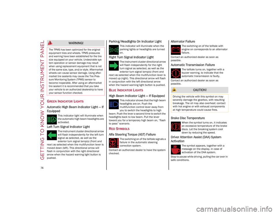
GREEN INDICATOR LIGHTS
Automatic High Beam Indicator Light — If
Equipped
This indicator light will illuminate when
the automatic high beam headlights are
activated.
Left Turn Signal Indicator Light
The instrument cluster directional arrow
will flash independently for the left turn
signal as selected, as well as the
exterior turn signal lamp(s) (front and
rear) as selected when the multifunction lever is
moved down (left). This directional arrow will
flash in conjunction with the right directional
arrow when the hazard warning light button is
pushed.
Parking/Headlights On Indicator Light
This indicator will illuminate when the
parking lights or headlights are turned
on.
Right Turn Signal Indicator Light
The instrument cluster directional arrow
will flash independently for the right
turn signal as selected, as well as the
exterior turn signal lamp(s) (front and
rear) as selected when the multifunction lever is
moved up (right). This directional arrow will flash
in conjunction with the left directional arrow
when the hazard warning light button is pushed.
BLUE INDICATOR LIGHTS
High Beam Indicator Light — If Equipped
This indicator shows that the high beam
headlights are on. Push the
multifunction control lever away from
you to switch the headlights to high
beam. Push the lever a second time to switch the
headlights back to low beam. Pull the lever
toward you for a temporary high beam on, “flash
to pass” scenario.
RED SYMBOLS
Alfa Steering Torque (AST) Failure
The switching on of the telltale signals a
failure in the automatic steering
correction system.
Contact an authorized dealer to have the system
checked.
Alternator Failure
The switching on of the telltale with
engine on corresponds to an alternator
failure.
Contact an authorized dealer as soon as
possible.
Automatic Transmission Failure
The telltale turns on, together with a
buzzer warning, to indicate that the
automatic transmission is faulty.
Contact an authorized dealer as soon as
possible.
Brake Disc Temperature
When the symbol turns on, it indicates
an excessive temperature of the brake
discs. Let the breaking system cool
down by reducing the speed.
Driver Attention Assist (DAA) System
Activation
The symbol appears, together with a
message on the display, in case of
activation of the DAA system.
Stop to pause while driving, pulling the car over in
safe conditions.
WARNING!
The TPMS has been optimized for the original
equipment tires and wheels. TPMS pressures
and warning have been established for the tire
size equipped on your vehicle. Undesirable sys -
tem operation or sensor damage may result
when using replacement equipment that is not
of the same size, type, and/or style. Aftermarket
wheels can cause sensor damage. Using after -
market tire sealants may cause the Tire Pres -
sure Monitoring System (TPMS) sensor to
become inoperable. After using an aftermarket
tire sealant it is recommended that you take
your vehicle to an authorized dealership to have
your sensor function checked.
CAUTION!
Driving the vehicle with this symbol on may
severely damage the gearbox, with resulting
breakage. The oil may also overheat: contact
with hot engine or with exhaust components
at high temperature could cause fires.
22_GU_OM_EN_USC_t.book Page 74
Page 126 of 256
STARTING AND OPERATING
124
REFUELING THE VEHICLE
Before refueling, make sure that the fuel type is
correct.
Also, stop the engine before refueling.
NOTE:
An inefficient catalytic converter leads to harmful
exhaust emissions, thus contributing to air pollu-
tion.
REFUELING CAPACITY
To ensure that you fill the tank completely, top off
twice after the first click of the fuel nozzle.
Further top-off could cause faults in the fuel
feeding system.
REFUELING PROCEDURE
The fuel filler door is unlocked when the central
door locking system is unlocked. It is automat -
ically locked when the central locking system is
applied. Opening The Fuel Filler Door
To refuel proceed as follows:
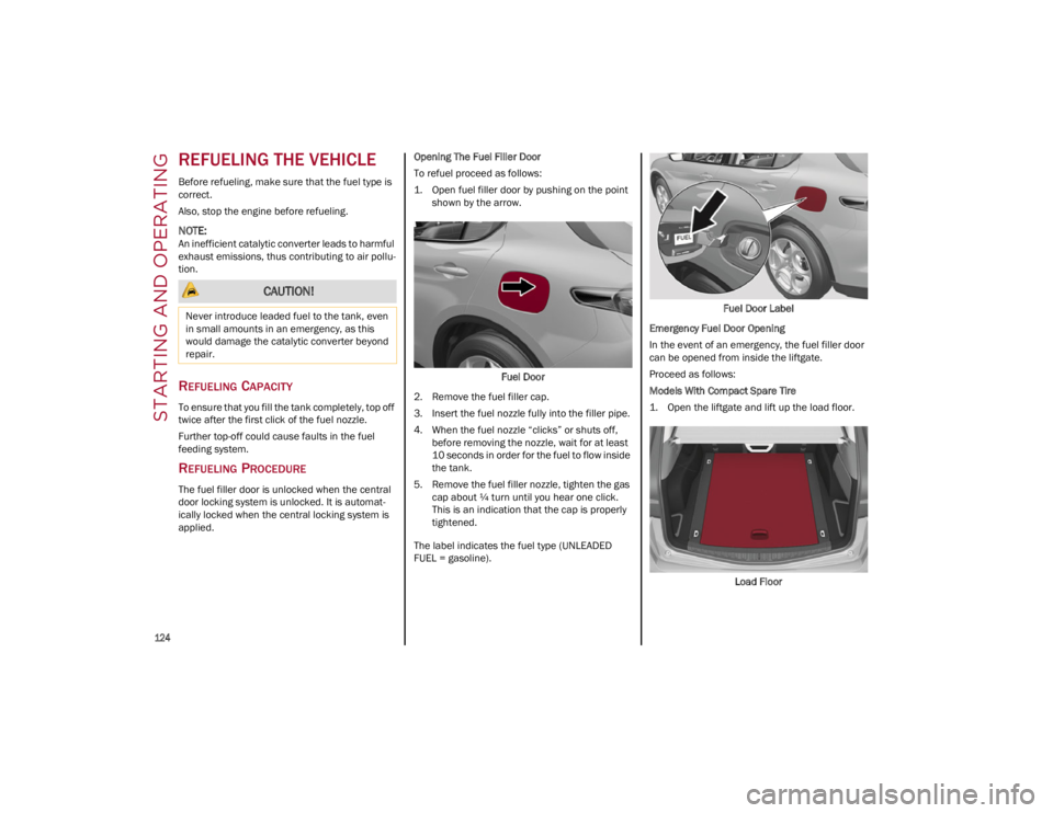
1. Open fuel filler door by pushing on the point
shown by the arrow.
Fuel Door
2. Remove the fuel filler cap.
3. Insert the fuel nozzle fully into the filler pipe.
4. When the fuel nozzle “clicks” or shuts off, before removing the nozzle, wait for at least
10 seconds in order for the fuel to flow inside
the tank.
5. Remove the fuel filler nozzle, tighten the gas cap about ¼ turn until you hear one click.
This is an indication that the cap is properly
tightened.
The label indicates the fuel type (UNLEADED
FUEL = gasoline). Fuel Door Label
Emergency Fuel Door Opening
In the event of an emergency, the fuel filler door
can be opened from inside the liftgate.
Proceed as follows:
Models With Compact Spare Tire
1. Open the liftgate and lift up the load floor.
Load Floor
CAUTION!
Never introduce leaded fuel to the tank, even
in small amounts in an emergency, as this
would damage the catalytic converter beyond
repair.
22_GU_OM_EN_USC_t.book Page 124
Page 129 of 256
127
TRAILER TOWING
In this section you will find safety tips and
information on limits to the type of towing you can
reasonably do with your vehicle. Before towing a
trailer, carefully review this information to tow
your load as efficiently and safely as possible.
To maintain the New Vehicle Limited Warranty
coverage, follow the requirements and
recommendations in this manual concerning
vehicles used for trailer towing.
COMMON TOWING DEFINITIONS
The following trailer towing related definitions will
assist you in understanding the following
information:
Gross Vehicle Weight Rating (GVWR)
The GVWR is the total allowable weight of your
vehicle. This includes driver, passengers, cargo
and tongue weight. The total load must be limited
so that you do not exceed the GVWR
Ú
page 126.
Gross Trailer Weight (GTW)
The GTW is the weight of the trailer plus the weight
of all cargo, consumables, and equipment
(permanent or temporary) loaded in or on the trailer
in its "loaded and ready for operation" condition.
The recommended way to measure GTW is to put
your fully loaded trailer on a vehicle scale. The
entire weight of the trailer must be supported by
the scale.
Gross Combination Weight Rating
(GCWR)
The GCWR is the total allowable weight of your
vehicle and trailer when weighed in combination.
Gross Axle Weight Rating (GAWR)
The GAWR is the maximum capacity of the front
and rear axles. Distribute the load over the front
and rear axles evenly. Make sure that you do not
exceed either front or rear GAWR
Ú
page 126.
Tongue Weight (TW)
The tongue weight is the downward force exerted
on the hitch ball by the trailer. You must consider
this as part of the load on your vehicle.
Trailer Frontal Area
The frontal area is the maximum height multiplied
by the maximum width of the front of a trailer.
Weight-Carrying Hitch
A weight-carrying hitch supports the trailer tongue
weight, just as if it were luggage located at a hitch
ball or some other connecting point of the vehicle.
These kinds of hitches are the most popular on
the market today and they are commonly used to
tow small and medium sized trailers.
Weight-Distributing Hitch
A weight-distributing hitch system works by
applying leverage through spring (load) bars. They
are typically used for heavier loads to distribute
trailer tongue weight to the tow vehicle's front
axle and the trailer axle(s). When used in
accordance with the manufacturer's directions, it
provides for a more level ride, offering more
consistent steering and brake control thereby
enhancing towing safety. The addition of a
friction/hydraulic sway control also dampens
sway caused by traffic and crosswinds and
contributes positively to tow vehicle and trailer
stability. Trailer Sway Control and a
weight-distributing (load equalizing) hitch are
recommended for heavier Tongue Weights (TW)
and may be required depending on vehicle and
trailer configuration/loading to comply with Gross
Axle Weight Rating (GAWR) requirements.
WARNING!
Do not load your vehicle any heavier than the
GVWR or the maximum front and rear GAWR. If
you do, parts on your vehicle can break, or it
can change the way your vehicle handles. This
could cause you to lose control. Overloading
can shorten the life of your vehicle.
WARNING!
It is important that you do not exceed the
maximum front or rear GAWR. A dangerous
driving condition can result if either rating is
exceeded. You could lose control of the vehicle
and have a collision.
WARNING!
An improperly adjusted weight-distributing
hitch system may reduce handling, stability,
braking performance, and could result in a
collision.
Weight-distributing hitch systems may not be
compatible with surge brake couplers.
Consult with the hitch and trailer
manufacturer or a reputable Recreational
Vehicle dealer for additional information.
22_GU_OM_EN_USC_t.book Page 127
Page 131 of 256
129
(Continued)
(Continued)
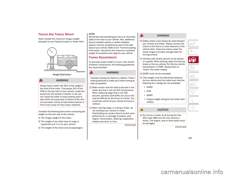
TRAILER AND TONGUE WEIGHT
Never exceed the maximum tongue weight
stamped on your fascia/bumper or trailer hitch.
Weight Distribution
Consider the following items when computing the
weight on the rear axle of the vehicle:
The tongue weight of the trailer.
The weight of any other type of cargo or
equipment put in or on your vehicle.
The weight of the driver and all passengers.
NOTE:Remember that everything put into or on the trailer
adds to the load on your vehicle. Also, additional
factory-installed options or dealer-installed
options must be considered as part of the total
load on your vehicle. Refer to the “Tire And Loading
Information” placard for the maximum combined
weight of occupants and cargo for your vehicle.
TOWING REQUIREMENTS
To promote proper break-in of your new vehicle
drivetrain components, the following guidelines
are recommended:
WARNING!
Always load a trailer with 60% of the weight in
the front of the trailer. This places 10% of the
GTW on the tow hitch of your vehicle. Loads bal -
anced over the wheels or heavier in the rear
can cause the trailer to sway severely side to
side which will cause loss of control of the vehi -
cle and trailer. Failure to load trailers heavier in
front is the cause of many trailer collisions.
WARNING!
Improper towing can lead to a collision. Follow
these guidelines to make your trailer towing as
safe as possible:
Make certain that the load is secured in the
trailer and that it will not shift during travel.
When trailering cargo that is not fully
secured, dynamic load shifts can occur that
may be difficult for the driver to control. You
could lose control of your vehicle and have a
collision.
When hauling cargo, or towing a trailer, do
not overload your vehicle or trailer.
Overloading can cause a loss of control, poor
performance, or damage to brakes, axle,
engine, transmission, steering, suspension,
chassis structure, or tires.
Safety chains must always be used between
your vehicle and trailer. Always connect the
chains to the frame or hook retainers of the
vehicle hitch. Cross the chains under the
trailer tongue and allow enough slack for
turning corners.
Vehicles with trailers should not be parked
on a grade. When parking, apply the parking
brake on the tow vehicle. Put the tow vehicle
transmission in PARK. Always block or
"chock" the trailer wheels.
GCWR must not be exceeded.
Total weight must be distributed between
the tow vehicle and the trailer such that the
following four ratings are not exceeded:
• GVWR
• GTW
• GAWR
• Tongue weight rating for the trailer hitch
utilized.
CAUTION!
Do not tow a trailer at all during the first
500 miles (805 km) the new vehicle is
driven. The engine, axle or other parts could
be damaged.
WARNING!
22_GU_OM_EN_USC_t.book Page 129
Page 139 of 256
137
HILL DESCENT CONTROL (HDC)
S
YSTEM — IF EQUIPPED
The HDC function is an integral part of the
Electronic Stability Control (ESC) system, keeping
the vehicle at a constant speed while descending
a hill by actively controlling the brakes.
HDC aims to create vehicle stability and safer
driving in various situations, including poor grip
conditions and steep descents.
The system has three different modes:
Off: the system is deactivated
Enabled: the system is enabled and ready to
intervene when the activation conditions are
met
Active: the system actively controls the vehicle
speed Enabling The System
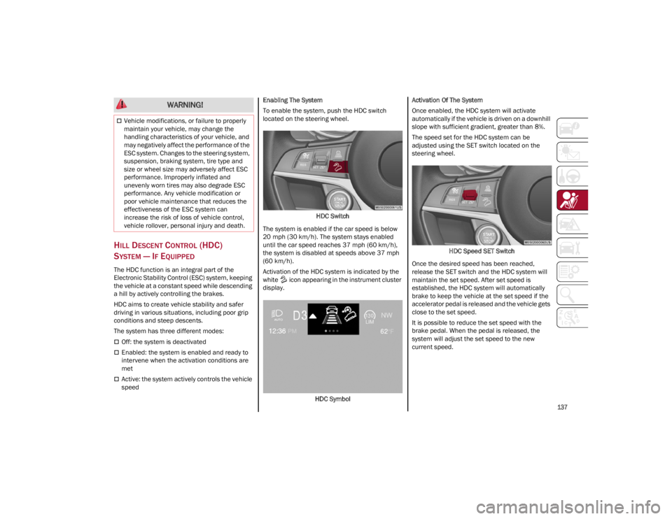
To enable the system, push the HDC switch
located on the steering wheel.
HDC Switch
The system is enabled if the car speed is below
20 mph (30 km/h). The system stays enabled
until the car speed reaches 37 mph (60 km/h),
the system is disabled at speeds above 37 mph
(60 km/h).
Activation of the HDC system is indicated by the
white icon appearing in the instrument cluster
display.
HDC Symbol Activation Of The System
Once enabled, the HDC system will activate
automatically if the vehicle is driven on a downhill
slope with sufficient gradient, greater than 8%.
The speed set for the HDC system can be
adjusted using the SET switch located on the
steering wheel.
HDC Speed SET Switch
Once the desired speed has been reached,
release the SET switch and the HDC system will
maintain the set speed. After set speed is
established, the HDC system will automatically
brake to keep the vehicle at the set speed if the
accelerator pedal is released and the vehicle gets
close to the set speed.
It is possible to reduce the set speed with the
brake pedal. When the pedal is released, the
system will adjust the set speed to the new
current speed.
Vehicle modifications, or failure to properly
maintain your vehicle, may change the
handling characteristics of your vehicle, and
may negatively affect the performance of the
ESC system. Changes to the steering system,
suspension, braking system, tire type and
size or wheel size may adversely affect ESC
performance. Improperly inflated and
unevenly worn tires may also degrade ESC
performance. Any vehicle modification or
poor vehicle maintenance that reduces the
effectiveness of the ESC system can
increase the risk of loss of vehicle control,
vehicle rollover, personal injury and death.
WARNING!
22_GU_OM_EN_USC_t.book Page 137
Page 152 of 256
SAFETY
150
The TPMS will signal the driver if pressure falls
below the warning limit for any reason, including
the effects of low temperature and normal loss of
pressure from the tire.
The TPMS will stop indicating insufficient tire
pressure when pressure is equal to or greater
than the prescribed cold inflation level.
Therefore, if insufficient tire pressure is indicated
by the ( ) warning light displaying in the
instrument cluster, increase the inflation
pressure up to the prescribed cold inflation value.
The system will automatically update, and the
TPMS Warning Light will turn off once the system
receives the updated tire pressures. The vehicle
may need to be driven for up to 20 minutes above
15 mph (24 km/h) in order for the TPMS to
receive this information.
NOTE:
The TPMS cannot indicate sudden tire pressure
drops (e.g. if a tire bursts). In this case, proceed
with caution and avoid abrupt steering.
Operating Example
For example, your vehicle may have a
recommended cold (parked for more than three
hours) placard pressure of 33 psi (227 kPa). If the
ambient temperature is 68°F (20°C), and the
measured tire pressure is 28 psi (193 kPa), a
temperature drop to 20°F (-7°C) will decrease the
tire pressure to approximately 24 psi (165 kPa).
This tire pressure is low enough to turn on the Tire
Pressure Monitoring Warning Light. Driving the
vehicle may cause the tire pressure to rise to
approximately 28 psi (193 kPa), but the TPMS
Warning Light will still be on. In this situation, the
TPMS Warning Light will turn off only after the tires
are inflated to the vehicle’s recommended cold
placard pressure value.
Insufficient Tire Pressure Indication
If an insufficient pressure value is detected on
one or more tires, the warning light in the
instrument cluster will display alongside the
dedicated messages, the system will highlight the
tire or tires with insufficient pressure graphically,
and an acoustic signal will be emitted.In this case, stop the vehicle, check the inflation
pressure of each tire, and inflate the necessary
tire or tires to the correct cold inflation pressure
value, shown on the display or in the dedicated
TPMS menu.
TPMS Temporarily Disabled:
TPMS Check Message
When a system fault is detected, the TPMS
Warning Light will flash on and off for 75 seconds,
and then remain on solid. The system fault will
also sound a chime. If the ignition is cycled, this
sequence will repeat, provided that the system
fault still exists. The TPMS Warning Light will turn
off when the fault condition no longer exists. A
system fault can occur due to any of the following:
Jamming due to electronic devices or driving
next to facilities emitting the same radio
frequencies as the TPMS sensors.
Installing some form of aftermarket window
tinting that affects radio wave signals.
Packed snow or ice around the wheels or
wheel housings.
Using tire chains on the vehicle.
Using wheels/tires not equipped with TPMS
sensors.
After the punctured tire has been repaired with
the original tire sealant contained in the tire kit,
the previous condition must be restored so that
the warning light is off during normal driving.
TPMS Deactivation
The TPMS can be deactivated by replacing all four
wheel and tire assemblies (road tires) with wheel
and tire assemblies that do not have TPMS
sensors, such as when installing winter wheel
and tire assemblies on your vehicle.
CAUTION!
The TPMS has been optimized for the
original equipment tires and wheels. TPMS
pressures and warning have been
established for the tire size equipped on your
vehicle. Undesirable system operation or
sensor damage may result when using
replacement equipment that is not of the
same size, type, and/or style. The TPMS
sensor is not designed for use on
aftermarket wheels and may contribute to a
poor overall system performance or sensor
damage. Customers are encouraged to use
OEM wheels to ensure proper TPMS feature
operation.
Using aftermarket tire sealants may cause
the Tire Pressure Monitoring System (TPMS)
sensor to become inoperable. After using an
aftermarket tire sealant it is recommended
that you take your vehicle to an authorized
dealer to have your sensor function checked.
After inspecting or adjusting the tire pressure
always reinstall the valve stem cap. This will
prevent moisture and dirt from entering the
valve stem, which could damage the TPMS
sensor.
22_GU_OM_EN_USC_t.book Page 150
Page 180 of 256
IN CASE OF EMERGENCY
178
(Continued)
(Continued)
System Requirements
Vehicle must have an operable 3G network
connection.
Vehicle must be powered with a properly
functioning electrical system.
The ignition must be in the RUN or ACC
position.
Frequently Asked Questions:
What happens if I accidentally push the SOS -
Emergency Call Button?
You have 10 seconds
after pushing the emergency button to cancel the
call. To cancel the call, push the button again.
What type of information is sent when I make an
SOS - Emergency Call from my vehicle? Certain
vehicle information, such as the VIN, is
transmitted along with last known GPS location.
Also note that emergency service operators may
record conversations and sounds within your
vehicle once a connection is made, and by using
the service you consent to having this information
shared.
When can I use the SOS - Emergency
Call button? You can ONLY use the
SOS - Emergency Call button to make a
call if you or someone else needs
emergency assistance.
JACKING AND TIRE
CHANGING
WARNING!
Never place anything on or near the vehicle’s
3G and GPS aerials. You could prevent 3G
and GPS signal reception, which can prevent
your vehicle from placing an emergency call.
An operable 3G network connection and a
GPS signal is required for the SOS-
Emergency Call system to function properly.
Do not add any aftermarket electrical
equipment to the vehicle’s electrical system.
This may prevent your vehicle from sending a
signal to initiate an emergency call. To avoid
interference that can cause the
SOS-Emergency Call system to fail, never
add aftermarket equipment (e.g., two-way
mobile radio, CB radio, data recorder, etc.) to
your vehicle’s electrical system or modify the
antennas on your vehicle. IF YOUR VEHICLE
AND SYSTEM LOSES BATTERY POWER FOR
ANY REASON (INCLUDING DURING OR AFTER
AN ACCIDENT) THE SOS FEATURES, APPS
AND SERVICES AMONG OTHERS WILL NOT
OPERATE.
The Occupant Restraint Controller (ORC)
turns on the air bag warning light in the
instrument cluster if a malfunction in any
part of the air bag system is detected. If the
air bag warning light is illuminated, the air
bag system may not be working properly and
the SOS-Emergency Call system may not be
able to send a signal to an emergency
service operator. If the air bag warning light
is illuminated, contact the Service Network
to have the air bag system checked
immediately.
Ignoring the LED on the SOS-Emergency Call
button could mean you will not have
emergency call services if needed. If the LED
on SOS-Emergency Call button is illuminated
red, contact the Service Network to have the
emergency call system checked
immediately.
If anyone in the vehicle could be in danger
(e.g., fire or smoke is visible, dangerous road
conditions or location), do not wait for voice
contact from an emergency service operator.
All occupants should exit the vehicle
immediately and move to a safe location.
Failure to perform scheduled maintenance
and regularly inspect your vehicle may result
in vehicle damage, accident or injury.
WARNING!
WARNING!
Do not attempt to change a tire on the side of
the vehicle close to moving traffic. Pull far
enough off the road to avoid the danger of
being hit when operating the jack or
changing the wheel.
22_GU_OM_EN_USC_t.book Page 178
Page 193 of 256
191
Correct servicing permits the performance of the
vehicle to be maintained over time, as well as
limited running costs and safeguarding the
efficiency of the safety systems.
SCHEDULED SERVICING
Correct servicing is crucial for guaranteeing a
long life for the vehicle under the best conditions.
For this reason, Alfa Romeo has planned a series
of checks and services for your vehicle at fixed
intervals based on distance and time, as
described in the Scheduled Servicing Plan.
Before each service, it is always necessary to
carefully follow the instructions in the Scheduled
Servicing Plan (e.g. periodically check level of
fluids, tire pressure, etc.).
Scheduled Servicing is offered by an authorized
dealer according to a set time schedule. If, during
each operation, in addition to the ones
scheduled, the need arises for further
replacements or repairs, these may be carried
out with the owner’s explicit consent only.
NOTE:
Scheduled Servicing intervals are required by the
manufacturer. Failure to have them carried out
may invalidate the New Vehicle Limited Warranty.
You are advised to inform an authorized dealer of
any small operating irregularities without waiting
for the next service.
PERIODIC CHECKS
Every month or every 620 miles (1,000 km) or
before long trips check and, if necessary, top off:
Engine coolant level.
Brake fluid level (if insufficient, see an
authorized dealer as soon as possible).
Windshield washer fluid level.
Tire inflation pressure and condition.
Operation of lighting system (headlights,
direction indicators, hazard warning lights,
etc.).
Operation of windshield washing/wiping
system and positioning/wear of wiper blades.
Inspect the CV/Universal joints.
Oil consumption of the engine depends on
conditions and driving style. For this reason, the
engine oil level must be checked every
1,860 miles (3,000 km), and top off if necessary;
for further information
Ú
page 197.
HEAVY USAGE OF THE VEHICLE
If the vehicle is used under one of the following
conditions:
Dusty roads.
Short, repeated journeys less than 4 miles
(7 km) at sub-zero outside temperatures.
Engine often idling or driving long distances at
low speeds or long periods of inactivity.
In the event of a long period of inactivity. The following checks must be carried out more
often than indicated in the Scheduled Servicing
Plan:
Check cleanliness of hood and liftgate locks,
cleanliness and lubrication of linkage.
Visually inspect conditions of: engine,
transmission, pipes and hoses (exhaust/fuel
system/brakes) and rubber elements
(sleeves/bushes, etc.).
Check battery charge and battery fluid level
(electrolyte).
Visually inspect conditions of the accessory
drive belts.
Check and, if necessary, change engine oil and
replace oil filter.
Check and, if necessary, replace cabin air
filter.
Check and, if necessary, replace air cleaner.
Severe Duty All Models
Change engine oil at 4,000 miles (6,500 km) if the vehicle is operated in a dusty and off-road
environment or is operated predominately at idle
or only very low engine RPM. This type of vehicle
use is considered Severe Duty.
22_GU_OM_EN_USC_t.book Page 191
Page 224 of 256
SERVICING AND MAINTENANCE
222
TIRES — GENERAL INFORMATION
Tire Pressure
Proper tire inflation pressure is essential to the
safe and satisfactory operation of your vehicle.
Four primary areas are affected by improper tire
pressure:
Safety
Fuel Economy
Tread Wear
Ride Comfort and Vehicle Stability
Safety Both underinflation and overinflation affect the
stability of the vehicle and can produce a feeling
of sluggish response or over responsiveness in
the steering.
NOTE:
Unequal tire pressures from side to side may
cause erratic and unpredictable steering
response.
Unequal tire pressure from side to side may
cause the vehicle to drift left or right.
Fuel Economy
Underinflated tires will increase tire rolling
resistance resulting in higher fuel consumption.
Tread Wear
Improper cold tire inflation pressures can cause
abnormal wear patterns and reduced tread life,
resulting in the need for earlier tire replacement.
Ride Comfort And Vehicle Stability
Proper tire inflation contributes to a comfortable
ride. Overinflation produces a jarring and
uncomfortable ride.
Tire Inflation Pressures
The proper cold tire inflation pressure is listed on
the driver's side B-pillar or rear edge of the
driver's side door.
At least once a month:
Check and adjust tire pressure with a good
quality pocket-type pressure gauge. Do not
make a visual judgement when determining
proper inflation. Tires may look properly
inflated even when they are underinflated.
Inspect tires for signs of tire wear or visible
damage. Inflation pressures specified on the placard are
always “cold tire inflation pressure”. Cold tire
inflation pressure is defined as the tire pressure
after the vehicle has not been driven for at least
three hours, or driven less than 1 mile (1.6 km)
after sitting for a minimum of three hours. The
cold tire inflation pressure must not exceed the
maximum inflation pressure molded into the tire
sidewall.
Check tire pressures more often if subject to a
wide range of outdoor temperatures, as tire
pressures vary with temperature changes.
Tire pressures change by approximately 1 psi
(7 kPa) per 12°F (7°C) of air temperature
change. Keep this in mind when checking tire
pressure inside a garage, especially in the Winter.
Example: If garage temperature = 68°F (20°C)
and the outside temperature = 32°F (0°C) then
the cold tire inflation pressure should be
increased by 3 psi (21 kPa), which equals 1 psi
(7 kPa) for every 12°F (7°C) for this outside
temperature condition.
Tire pressure may increase from 2 to 6 psi (13 to
40 kPa) during operation. DO NOT reduce this
normal pressure build up or your tire pressure will
be too low.
WARNING!
Improperly inflated tires are dangerous and
can cause collisions.
Underinflation increases tire flexing and can
result in overheating and tire failure.
Overinflation reduces a tire's ability to
cushion shock. Objects on the road and
chuckholes can cause damage that result in
tire failure.
Overinflated or underinflated tires can affect
vehicle handling and can fail suddenly,
resulting in loss of vehicle control.
Unequal tire pressures can cause steering
problems. You could lose control of your
vehicle.
Unequal tire pressures from one side of the
vehicle to the other can cause the vehicle to
drift to the right or left.
Always drive with each tire inflated to the
recommended cold tire inflation pressure.
CAUTION!
After inspecting or adjusting the tire pressure,
always reinstall the valve stem cap. This will
prevent moisture and dirt from entering the
valve stem, which could damage the valve
stem.
22_GU_OM_EN_USC_t.book Page 222