warning lights ALFA ROMEO STELVIO 2022 Owners Manual
[x] Cancel search | Manufacturer: ALFA ROMEO, Model Year: 2022, Model line: STELVIO, Model: ALFA ROMEO STELVIO 2022Pages: 256, PDF Size: 10.17 MB
Page 11 of 256
9
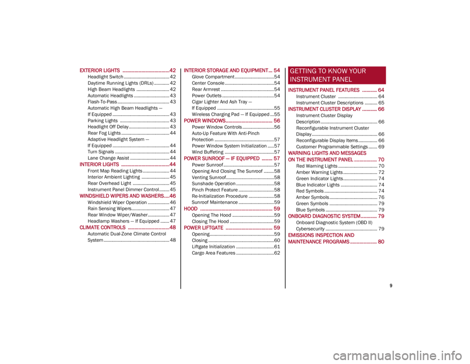
EXTERIOR LIGHTS ...................................42
Headlight Switch .................................... 42
Daytime Running Lights (DRLs) ............ 42
High Beam Headlights .......................... 42
Automatic Headlights ............................ 43
Flash-To-Pass ......................................... 43
Automatic High Beam Headlights —
If Equipped ............................................. 43 Parking Lights ....................................... 43
Headlight Off Delay ................................ 43
Rear Fog Lights ...................................... 44
Adaptive Headlight System —
If Equipped ............................................. 44 Turn Signals ........................................... 44
Lane Change Assist ............................... 44
INTERIOR LIGHTS ....................................44
Front Map Reading Lights ..................... 44
Interior Ambient Lighting ...................... 45
Rear Overhead Light ............................. 45
Instrument Panel Dimmer Control ........ 45
WINDSHIELD WIPERS AND WASHERS....46
Windshield Wiper Operation ................. 46
Rain Sensing Wipers.............................. 47
Rear Window Wiper/Washer................. 47
Headlamp Washers — If Equipped ....... 47
CLIMATE CONTROLS ...............................48
Automatic Dual-Zone Climate Control
System .................................................... 48
INTERIOR STORAGE AND EQUIPMENT ... 54
Glove Compartment ...............................54
Center Console .......................................54
Rear Armrest ..........................................54
Power Outlets .........................................54
Cigar Lighter And Ash Tray —
If Equipped .............................................55 Wireless Charging Pad — If Equipped ...55
POWER WINDOWS................................... 56
Power Window Controls .........................56
Auto-Up Feature With Anti-Pinch
Protection ............................................... 57 Power Window System Initialization .....57
Wind Buffeting .......................................57
POWER SUNROOF — IF EQUIPPED ........ 57
Power Sunroof ........................................ 57
Opening And Closing The Sunroof ........58
Venting Sunroof......................................58
Sunshade Operation ..............................58
Pinch Protect Feature ............................58
Re-Initialization Procedure ....................58
Sunroof Maintenance ............................59
HOOD ...................................................... 59
Opening The Hood ................................. 59
Closing The Hood ...................................59
POWER LIFTGATE ................................... 59
Opening...................................................59
Closing ....................................................60
Liftgate Initialization ..............................61
Cargo Area Features ..............................62
GETTING TO KNOW YOUR
INSTRUMENT PANEL
INSTRUMENT PANEL FEATURES ........... 64
Instrument Cluster ............................... 64
Instrument Cluster Descriptions .......... 65
INSTRUMENT CLUSTER DISPLAY ........... 66
Instrument Cluster Display
Description ............................................. 66 Reconfigurable Instrument Cluster
Display .................................................... 66 Reconfigurable Display Items ............... 66
Customer Programmable Settings ....... 69
WARNING LIGHTS AND MESSAGES
ON THE INSTRUMENT PANEL ................. 70
Red Warning Lights ............................... 70
Amber Warning Lights ........................... 72
Green Indicator Lights........................... 74
Blue Indicator Lights ............................. 74
Red Symbols .......................................... 74
Amber Symbols ...................................... 76
Green Symbols ...................................... 79
Blue Symbols ......................................... 79
ONBOARD DIAGNOSTIC SYSTEM ............ 79
Onboard Diagnostic System (OBD II)
Cybersecurity ......................................... 79
EMISSIONS INSPECTION AND
MAINTENANCE PROGRAMS .................... 80
22_GU_OM_EN_USC_t.book Page 9
Page 16 of 256
SYMBOL GLOSSARY
14
SYMBOL GLOSSARY
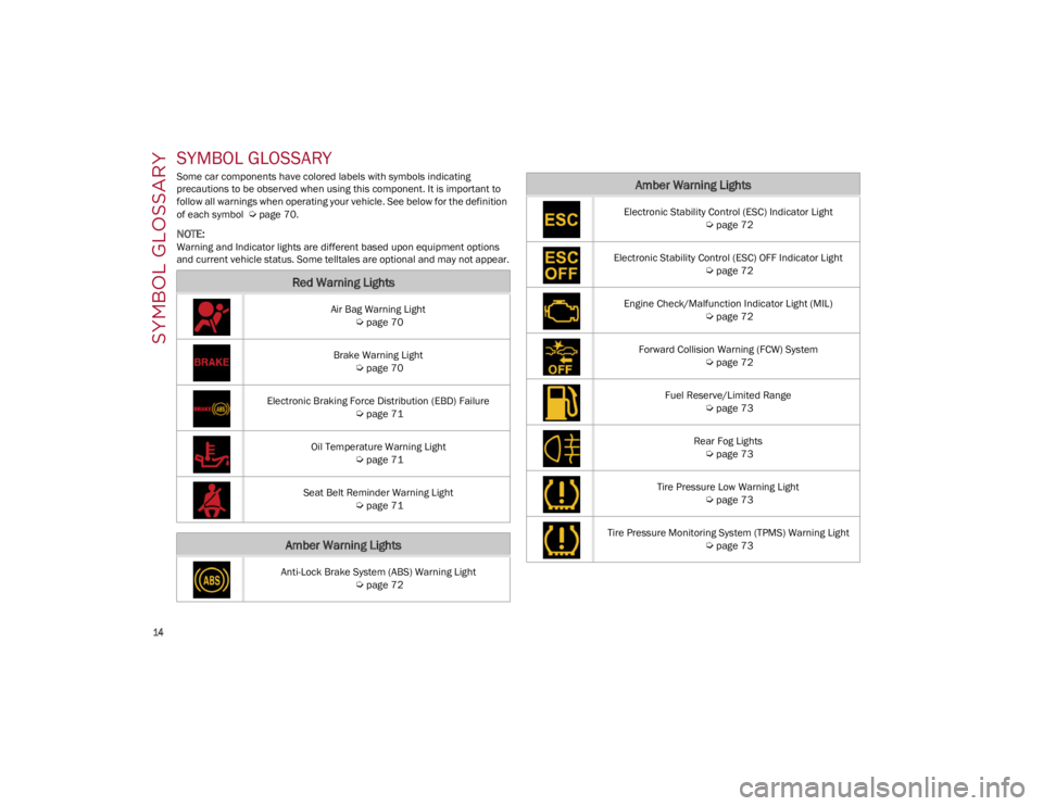
Some car components have colored labels with symbols indicating
precautions to be observed when using this component. It is important to
follow all warnings when operating your vehicle. See below for the definition
of each symbol
Ú
page 70.
NOTE:
Warning and Indicator lights are different based upon equipment options
and current vehicle status. Some telltales are optional and may not appear.
Red Warning Lights
Air Bag Warning Light
Ú
page 70
Brake Warning Light
Ú
page 70
Electronic Braking Force Distribution (EBD) Failure
Ú
page 71
Oil Temperature Warning Light
Ú
page 71
Seat Belt Reminder Warning Light
Ú
page 71
Amber Warning Lights
Anti-Lock Brake System (ABS) Warning Light
Ú
page 72
Electronic Stability Control (ESC) Indicator Light
Ú
page 72
Electronic Stability Control (ESC) OFF Indicator Light
Ú
page 72
Engine Check/Malfunction Indicator Light (MIL)
Ú
page 72
Forward Collision Warning (FCW) System
Ú
page 72
Fuel Reserve/Limited Range
Ú
page 73
Rear Fog Lights
Ú
page 73
Tire Pressure Low Warning Light
Ú
page 73
Tire Pressure Monitoring System (TPMS) Warning Light
Ú
page 73
Amber Warning Lights
22_GU_OM_EN_USC_t.book Page 14
Page 17 of 256
15
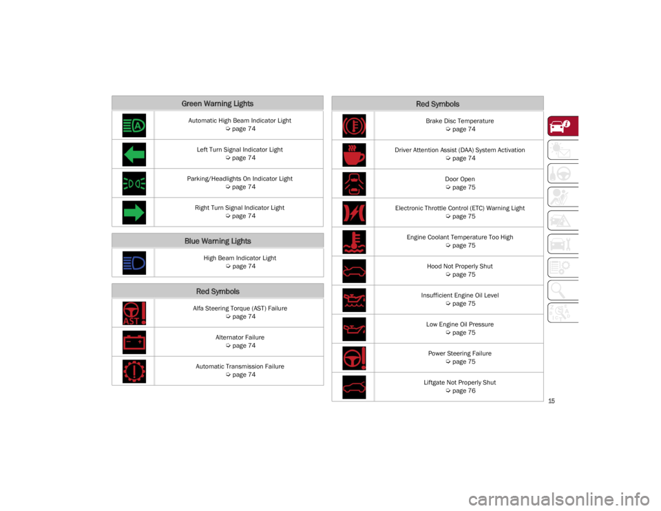
Green Warning Lights
Automatic High Beam Indicator Light
Ú
page 74
Left Turn Signal Indicator Light
Ú
page 74
Parking/Headlights On Indicator Light
Ú
page 74
Right Turn Signal Indicator Light
Ú
page 74
Blue Warning Lights
High Beam Indicator Light
Ú
page 74
Red Symbols
Alfa Steering Torque (AST) Failure
Ú
page 74
Alternator Failure
Ú
page 74
Automatic Transmission Failure
Ú
page 74
Brake Disc Temperature
Ú
page 74
Driver Attention Assist (DAA) System Activation
Ú
page 74
Door Open
Ú
page 75
Electronic Throttle Control (ETC) Warning Light
Ú
page 75
Engine Coolant Temperature Too High
Ú
page 75
Hood Not Properly Shut
Ú
page 75
Insufficient Engine Oil Level
Ú
page 75
Low Engine Oil Pressure
Ú
page 75
Power Steering Failure
Ú
page 75
Liftgate Not Properly Shut
Ú
page 76
Red Symbols
22_GU_OM_EN_USC_t.book Page 15
Page 18 of 256
SYMBOL GLOSSARY
16
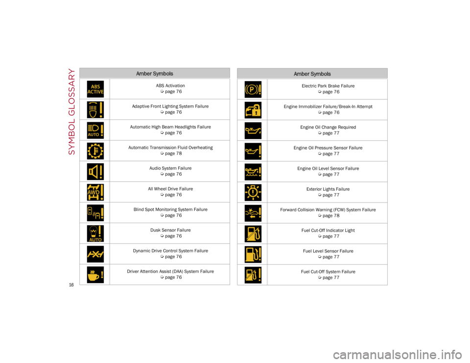
Amber Symbols
ABS Activation
Ú
page 76
Adaptive Front Lighting System Failure
Ú
page 76
Automatic High Beam Headlights Failure
Ú
page 76
Automatic Transmission Fluid Overheating
Ú
page 78
Audio System Failure
Ú
page 76
All Wheel Drive Failure
Ú
page 76
Blind Spot Monitoring System Failure
Ú
page 76
Dusk Sensor Failure
Ú
page 76
Dynamic Drive Control System Failure
Ú
page 76
Driver Attention Assist (DAA) System Failure
Ú
page 76
Electric Park Brake Failure
Ú
page 76
Engine Immobilizer Failure/Break-In Attempt
Ú
page 76
Engine Oil Change Required
Ú
page 77
Engine Oil Pressure Sensor Failure
Ú
page 77
Engine Oil Level Sensor Failure
Ú
page 77
Exterior Lights Failure
Ú
page 77
Forward Collision Warning (FCW) System Failure
Ú
page 78
Fuel Cut-Off Indicator Light
Ú
page 77
Fuel Level Sensor Failure
Ú
page 77
Fuel Cut-Off System Failure
Ú
page 77
Amber Symbols
22_GU_OM_EN_USC_t.book Page 16
Page 25 of 256
23
REMOTE START —
IF EQUIPPED
This system uses the key fob to start the
engine conveniently from outside the
vehicle while still maintaining security.
NOTE:
Obstructions between the vehicle and key fob
may reduce this range
Ú
page 247.
HOW TO USE REMOTE START
Push the Remote Start button on the key fob
twice within five seconds. The vehicle doors will
lock, the turn signals will flash twice, and the horn
will chirp twice. Pushing the Remote Start button
a third time shuts the engine off.
NOTE:
With Remote Start, the engine will only run for
15 minutes.
Remote Start can only be used twice.
If an engine fault is present or fuel level is low,
the vehicle will start and then shut down in 10
seconds.
The parking lights will turn on and remain on
during Remote Start mode.
For security, power window and power sunroof
(if equipped) operation is disabled when the
vehicle is in the Remote Start mode.
The ignition must be placed in the ACC position
before the Remote Start sequence can be
repeated for a third cycle.
All of the following conditions must be met before
the engine will remote start:
Gear selector in PARK
Doors closed
Hood closed
Liftgate closed
Hazard switch off
Brake switch inactive (brake pedal not
pressed)
Battery at an acceptable charge level
PANIC button not pushed
System not disabled from previous Remote
Start event
Vehicle Security system indicator flashing
Ignition in OFF position
Fuel level meets minimum requirement
Vehicle Security system is not signaling an
intrusion
Malfunction Indicator Light (MIL) is not
illuminated
TO EXIT REMOTE START MODE
To drive the vehicle after starting the Remote
Start system, either push and release the unlock
button on the key fob to unlock the doors, or
unlock the vehicle using Passive Entry via the
door handles, and disarm the Vehicle Security
system (if equipped). Then, prior to the end of the
15 minute cycle, push and release the START/
STOP ignition button while pressing the brake
pedal.
The Remote Start system will turn the engine off
if the Remote Start button is pushed again, or if
the engine is allowed to run for the entire
15 minute cycle.
REMOTE START COMFORT SYSTEMS —
I
F EQUIPPED
When Remote Start is activated, the heated
steering wheel and front heated seat features will
automatically activate when ambient
temperature is less than 39°F (4°C). These
features will stay on through the duration of
Remote Start.
NOTE:
This feature can be activated through the radio
system. Refer to the Information and Entertain -
ment System Owner’s Manual Supplement for
further information.
WARNING!
Do not start or run an engine in a closed
garage or confined area. Exhaust gas
contains Carbon Monoxide (CO) which is
odorless and colorless. Carbon Monoxide is
poisonous and can cause serious injury or
death when inhaled.
Keep key fobs away from children. Operation
of the Remote Start system, windows, door
locks or other controls could cause serious
injury or death.
22_GU_OM_EN_USC_t.book Page 23
Page 44 of 256
GETTING TO KNOW YOUR VEHICLE
42
If you have any problems, or require assistance,
please call toll-free 1-800-355-3515 or, on the
Internet at
HomeLink.com
for information or
assistance.
EXTERIOR LIGHTS
HEADLIGHT SWITCH
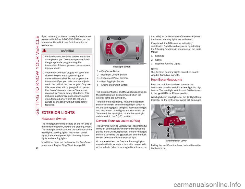
The headlight switch is located on the left side of
the instrument panel, next to the steering wheel.
The headlight switch controls the operation of the
headlights, parking lights, instrument panel
lights, instrument panel light dimming, interior
lights and rear fog lights.
In addition, there are buttons for the ParkSense
system and Engine Stop/Start
Ú
page 81. Headlight Switch
The instrument panel and the various controls on
the dashboard will be illuminated when the
exterior lights are turned on.
To turn on the headlights, rotate the headlight
switch clockwise. When the headlight switch is
on, the parking lights, taillights, license plate light
and instrument panel lights are also turned on.
To turn off the headlights, rotate the headlight
switch back to the O (off) position.
DAYTIME RUNNING LIGHTS (DRLS)
The Daytime Running Lights (DRLs) (low intensity)
come on automatically whenever the ignition is
placed in the ON/RUN position, and the headlight
switch is turned to the position, and the dusk
sensor detects sufficient external light.
On some vehicles, the Daytime Running Lights
may deactivate, or reduce intensity, on one side
of the vehicle (when a turn signal is activated on that side), or on both sides of the vehicle (when
the hazard warning lights are activated).
If equipped, the DRLs can be activated/
deactivated from the radio system, by selecting
the following functions in sequence on the main
MENU:
1. Settings
2. Lights
3. Daytime Running Lights
NOTE:
The Daytime Running Lights
cannot be deacti -
vated in Canadian markets.
HIGH BEAM HEADLIGHTS
Push the multifunction lever towards the
instrument panel to switch the headlights to high
beams. The headlight switch must first be turned
to the (AUTO) or (on) position.
With high beam headlights on, the High Beam
Indicator on the instrument panel will illuminate.
Multifunction Lever
Pulling the multifunction lever back will turn the
low beams on.
WARNING!
Vehicle exhaust contains carbon monoxide,
a dangerous gas. Do not run your vehicle in
the garage while programming the
transceiver. Exhaust gas can cause serious
injury or death.
Your motorized door or gate will open and
close while you are programming the
universal transceiver. Do not program the
transceiver if people, pets or other objects
are in the path of the door or gate. Only use
this transceiver with a garage door opener
that has a “stop and reverse” feature as
required by Federal safety standards. This
includes most garage door opener models
manufactured after 1982. Do not use a
garage door opener without these safety
features.1 — ParkSense Button
2 — Headlight Control Switch
3 — Instrument Panel Dimmer
4 — Rear Fog Light Button
5 — Engine Stop/Start Button
22_GU_OM_EN_USC_t.book Page 42
Page 45 of 256
43
AUTOMATIC HEADLIGHTS
This system automatically turns the headlights on
or off according to ambient light levels. To turn
the system on, rotate the headlight switch to the (AUTO) position.
NOTE:
The function can only operate with the ignition in
the ON/RUN position.
To turn the automatic headlights off, turn the
headlight switch out of the (AUTO) position.
FLASH-TO-PASS
You can signal another vehicle with your
headlights by lightly pulling the multifunction
lever toward you. This will cause the high beam
headlights to turn on, and remain on, until the
lever is released.
AUTOMATIC HIGH BEAM HEADLIGHTS —
I
F EQUIPPED
The Automatic High Beam Headlights system
provides increased forward lighting at night by
automating high beam control through the use of
a camera mounted on the windshield. This
camera detects vehicle specific light and
automatically switches from high beams to low
beams until the approaching vehicle is out of
view.
This function is enabled with the radio system,
and can only be activated with the light switch
turned to (auto).
If the high beam headlights are on, the blue icon/
warning light will illuminate in the instrument
panel. When the speed is higher than 25 mph (40 km/h)
and the function is active, the lights will turn off if
the multifunction lever is pushed again.
When the speed is lower than 15 mph (25 km/h)
and the function is active, the function switches
the high beam headlights off.
If the high beam headlights are operated quickly
again (pushing the multifunction lever towards
the instrument panel), the warning light/icon
will illuminate in the instrument panel, and the
high beam headlights will turn on constantly until
the speed exceeds 25 mph (40 km/h).
When the speed of 25 mph (40 km/h) is
exceeded again, the automatic functioning is
reactivated.
If the multifunction lever is pushed again with the
Automatic High Beam Headlights activated, the
Automatic High Beam Headlights function
deactivates.
To deactivate the automatic headlight function,
rotate the headlight switch to the position.
NOTE:
If the system recognizes heavy traffic areas,
the automatic functions remain disabled
independently of the vehicle’s speed.
The Automatic High Beam functionality may
also be influenced by:
• Reflections on road signs
• Dim headlights from oncoming traffic
• Poor weather conditions
• Presence of dirt or other obstructions on
the sensor
• Damage to the windshield
PARKING LIGHTS
To turn on the parking lights and instrument
panel lights, rotate the headlight switch clockwise
to the position. All of the parking lights will turn
on for eight minutes, and opening the door
activates an audible warning.
To leave only the lights on one side (right/left)
illuminated, move the multifunction lever
(located on the left side of the steering wheel) to
the side that you want to remain on. With the
parking lights on, the indicator light on the
instrument panel will illuminate.
To turn off the parking lights, rotate the headlight
switch back to the O (off) position.
HEADLIGHT OFF DELAY
To assist when exiting the vehicle, the “Headlight
Off Delay” feature will leave the headlights on for
up to 90 seconds. This delay is initiated when the
ignition is placed in the OFF position while the
headlight switch is on, and then the headlight
switch is cycled off. Headlight delay can be
canceled by either turning on the headlights or
side lights, or by placing the ignition in the ON
position.
The function can be activated from the radio
system by selecting the following functions in
sequence on the main menu:
1. Settings
2. Lights
3. Headlight Off Delay
22_GU_OM_EN_USC_t.book Page 43
Page 68 of 256
GETTING TO KNOW YOUR INSTRUMENT PANEL
66
3. Instrument Cluster Display•The instrument cluster display features a
driver interactive display
Ú
page 66.
4. Fuel Gauge •The digital bar gauge shows the amount of
fuel in the tank.
• The fuel reserve/limited range warning
light turns on, a message is displayed and
there is an acoustic signal when about 2.4 gallons (9 liters) of fuel are left in the tank.
• The fuel pump symbol points to the
side of the vehicle where the fuel door is
lo cated.
• Proceeding further, the second white
notch will go off and the last one will become red, together with the indication "E" present at the bottom of the tank. Fuel Level Gauge
NOTE:
If the low fuel warning light switches on, refuel at
the earliest opportunity.
5. Speedometer
•Indicates vehicle speed.
NOTE:
The hard telltales will illuminate for a bulb check
when the ignition is first cycled.
INSTRUMENT CLUSTER
DISPLAY
INSTRUMENT CLUSTER DISPLAY
D
ESCRIPTION
This vehicle is equipped with a driver interactive
display that is located in the instrument cluster.
When one or more of the doors have been
opened or closed and the ignition is in the OFF
position, the instrument cluster will display the
vehicle mileage for a few seconds.
RECONFIGURABLE INSTRUMENT CLUSTER
D
ISPLAY
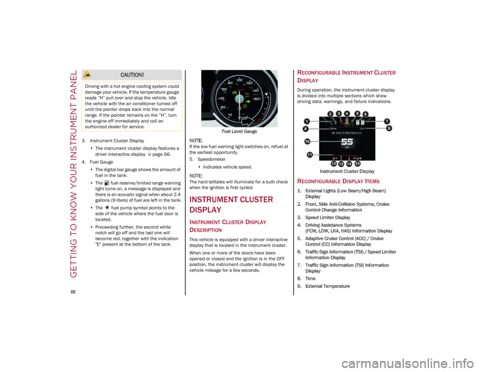
During operation, the instrument cluster display
is divided into multiple sections which show
driving data, warnings, and failure indications.
Instrument Cluster Display
RECONFIGURABLE DISPLAY ITEMS
1. External Lights (Low Beam/High Beam)Display
2. Front, Side Anti-Collision Systems, Cruise Control Change Information
3. Speed Limiter Display
4. Driving Assistance Systems (FCW, LDW, LKA, HAS) Information Display
5. Adaptive Cruise Control (ACC) / Cruise Control (CC) Information Display
6. Traffic Sign Information (TSI) / Speed Limiter Information Display
7. Traffic Sign Information (TSI) Information Display
8. Time
9. External Temperature
CAUTION!
Driving with a hot engine cooling system could
damage your vehicle. If the temperature gauge
reads “H” pull over and stop the vehicle. Idle
the vehicle with the air conditioner turned off
until the pointer drops back into the normal
range. If the pointer remains on the “H”, turn
the engine off immediately and call an
authorized dealer for service.
22_GU_OM_EN_USC_t.book Page 66
Page 72 of 256
GETTING TO KNOW YOUR INSTRUMENT PANEL
70
Clock & Date
The following settings can be modified under the
“Clock & Date” menu:
Sync With GPS Time: activates or deactivates
the clock synchronization through the GPS. If
the function is deactivated, the options Set
Time and Set Date are enabled.
Set Time: set the time manually.
Time Format: set the time format to either a
12-hour or a 24-hour clock.
Set Date: set the date manually.
Restore Clock & Date Settings: restores the
factory settings.
To access and change the setting, turn and push
the Rotary Pad or press the desired setting on the
touchscreen.
Cluster
The following settings can be modified under the
“Cluster” menu:
Warning Buzzer Volume: set the volume of the
warning buzzer on seven levels.
Trip B: activate or deactivate the Trip function.
Show Phone Info: activate/deactivate
repetition of the phone function screens also
on the instrument cluster display.
Show Audio Info: activate/deactivate
repetition of the audio function screens (Radio
and Media) also on the instrument cluster
display.
Show Nav Info: activate/deactivate repetition
of the navigator function screens also on the
instrument cluster display.
Digital Speed on all screens: activate/deacti -
vating of digital speed on the instrument
cluster display screens other than the main
screen.
Consumption Bar: activate/deactivate the
consumption baron the display screens of the
instrument panel where it is available.
Performance Pages: choose, for each driving
mode, one of the two alternative contents
displayed in the screen.
Custom Areas: select which content to display
in each of the three customizable areas on the
display of the instrument panel: time, date,
outside temperature, radio information,
compass.
Restore Cluster Settings: deletes the current
settings and restores the factory settings.
To access and the change the setting, turn and
push the Rotary Pad or press the desired setting
on the touchscreen.
WARNING LIGHTS AND
MESSAGES ON THE
INSTRUMENT PANEL
The following pages consist of warning lights and
messages.
NOTE:
The warning light turns on together with a
dedicated message and/or chime when
applicable. These indications are precau -
tionary and as such must not be considered as
exhaustive and/or alternative to the
information contained in the Owner’s Manual, which you are advised to read carefully in all
cases. Always refer to the information in this
section in the event of a failure indication.
The failure indicators appearing on the display
are divided into two categories: very serious
and less serious faults. Serious faults are
indicated by a repeated and prolonged
warning cycle. Less serious faults are
indicated by a warning cycle with a shorter
duration. You can stop the warning cycle in
both cases by pushing the button located on
the windshield wiper stalk. The instrument
panel warning light will stay on until the cause
of the failure is eliminated.
RED WARNING LIGHTS
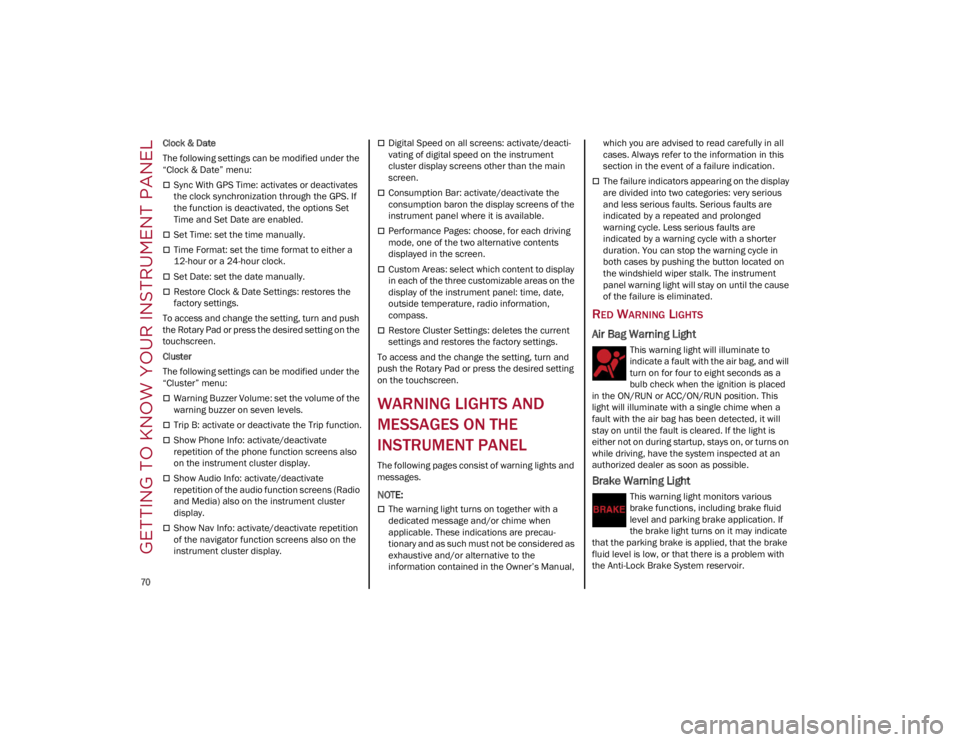
Air Bag Warning Light
This warning light will illuminate to
indicate a fault with the air bag, and will
turn on for four to eight seconds as a
bulb check when the ignition is placed
in the ON/RUN or ACC/ON/RUN position. This
light will illuminate with a single chime when a
fault with the air bag has been detected, it will
stay on until the fault is cleared. If the light is
either not on during startup, stays on, or turns on
while driving, have the system inspected at an
authorized dealer as soon as possible.
Brake Warning Light
This warning light monitors various
brake functions, including brake fluid
level and parking brake application. If
the brake light turns on it may indicate
that the parking brake is applied, that the brake
fluid level is low, or that there is a problem with
the Anti-Lock Brake System reservoir.
22_GU_OM_EN_USC_t.book Page 70
Page 73 of 256
71
(Continued)
If the light remains on when the parking brake has
been disengaged, and the fluid level is at the full
mark on the master cylinder reservoir, it indicates
a possible brake hydraulic system malfunction or
that a problem with the Brake Booster has been
detected by the Anti-Lock Brake System (ABS) /
Electronic Stability Control (ESC) system. In this
case, the light will remain on until the condition
has been corrected. If the problem is related to the
brake booster, the ABS pump will run when
applying the brake, and a brake pedal pulsation
may be felt during each stop.
The dual brake system provides a reserve braking
capacity in the event of a failure to a portion of the
hydraulic system. A leak in either half of the dual
brake system is indicated by the Brake Warning
Light, which will turn on when the brake fluid level
in the master cylinder has dropped below a
specified level.
The light will remain on until the cause is corrected.
NOTE:
The light may flash momentarily during sharp
cornering maneuvers, which change fluid level
conditions. The vehicle should have service
performed, and the brake fluid level checked.
If brake failure is indicated, immediate repair is
necessary.
Vehicles equipped with the Anti-Lock Brake
System (ABS) are also equipped with Electronic
Brake Force Distribution (EBD). In the event of an
EBD failure, the Brake Warning Light will turn on
along with the ABS Light. Immediate repair to the
ABS system is required.
Operation of the Brake Warning Light can be
checked by turning the ignition switch from the
OFF position to the ON/RUN position. The light
should illuminate for approximately two seconds.
The light should then turn off unless the parking
brake is applied or a brake fault is detected. If the
light does not illuminate, have the light inspected
by an authorized dealer.
The light also will turn on when the parking brake
is applied with the ignition switch in the ON/RUN
position.
NOTE:
This light shows only that the parking brake is
applied. It does not show the degree of brake
application.
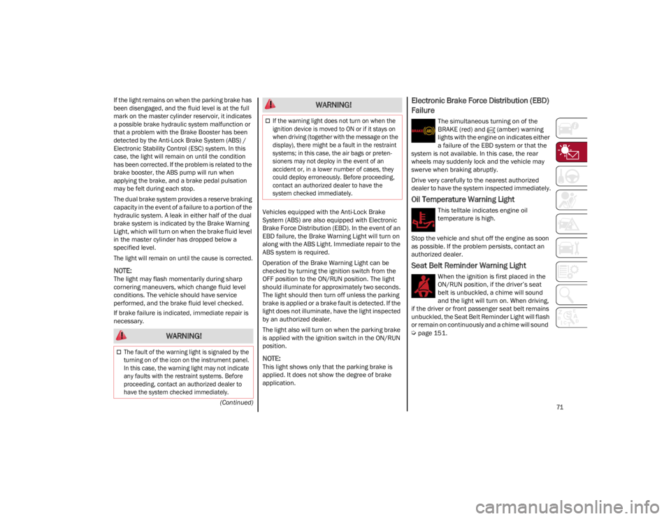
Electronic Brake Force Distribution (EBD)
Failure
The simultaneous turning on of the
BRAKE (red) and (amber) warning
lights with the engine on indicates either
a failure of the EBD system or that the
system is not available. In this case, the rear
wheels may suddenly lock and the vehicle may
swerve when braking abruptly.
Drive very carefully to the nearest authorized
dealer to have the system inspected immediately.
Oil Temperature Warning Light
This telltale indicates engine oil
temperature is high.
Stop the vehicle and shut off the engine as soon
as possible. If the problem persists, contact an
authorized dealer.
Seat Belt Reminder Warning Light
When the ignition is first placed in the
ON/RUN position, if the driver’s seat
belt is unbuckled, a chime will sound
and the light will turn on. When driving,
if the driver or front passenger seat belt remains
unbuckled, the Seat Belt Reminder Light will flash
or remain on continuously and a chime will sound
Ú
page 151. WARNING!
The fault of the warning light is signaled by the
turning on of the icon on the instrument panel.
In this case, the warning light may not indicate
any faults with the restraint systems. Before
proceeding, contact an authorized dealer to
have the system checked immediately.
If the warning light does not turn on when the
ignition device is moved to ON or if it stays on
when driving (together with the message on the
display), there might be a fault in the restraint
systems; in this case, the air bags or preten -
sioners may not deploy in the event of an
accident or, in a lower number of cases, they
could deploy erroneously. Before proceeding,
contact an authorized dealer to have the
system checked immediately.
WARNING!
22_GU_OM_EN_USC_t.book Page 71