start stop button ALFA ROMEO STELVIO 2023 User Guide
[x] Cancel search | Manufacturer: ALFA ROMEO, Model Year: 2023, Model line: STELVIO, Model: ALFA ROMEO STELVIO 2023Pages: 268, PDF Size: 10.36 MB
Page 97 of 268
95
Deactivation
To deactivate the sequential driving mode, bring
the gear selector back in position DRIVE (D)
("automatic" driving mode).
NOTE:
To select the correct gear for maximum
deceleration (engine brake), keep the gear
paddle pulled (–): the transmission goes to
an operating mode in which the vehicle can
slow down easily.
The vehicle will keep the gear selected by the
driver until the safety conditions allow it.
This means, for example, that the system will
try to prevent the engine from switching off,
automatically downshifting if the engine speed
is too low.
AUTOMATIC TRANSMISSION LIMP HOME
M
ODE
Transmission function is monitored electronically
for abnormal conditions. If a condition is detected
that could result in transmission damage,
Transmission Limp Home Mode is activated. In this condition, the transmission stays in
FOURTH gear, regardless of the selected gear.
Positions PARK (P), REVERSE (R) and
NEUTRAL (N) still work.
The symbol might light up in the instrument
cluster.
Temporary failure
In the event of a momentary problem, the
transmission can be reset to regain all forward
gears by performing the following steps:
1. Stop the vehicle.
2. Shift the transmission into PARK (P), if
possible. If not, shift the transmission to
NEUTRAL (N).
3. Push and hold the ignition until the engine turns off.
4. Wait for about 10 seconds, then restart the engine.
5. Shift into the desired gear range. If the problem is no longer detected, the transmis -
sion will return to normal operation.
NOTE:
Even if the transmission can be reset, we recom -
mend that you visit an authorized dealer at your
earliest possible convenience. An authorized
dealer has diagnostic equipment to determine if
the problem could reoccur. If the transmission
cannot be reset, service is required at an autho -
rized dealer.
BRAKE TRANSMISSION SHIFT INTERLOCK
(BTSI) S
YSTEM
This vehicle is equipped with a BTSI that holds the
gear selector in PARK (P) unless the brakes are
applied.
This system prevents you from moving the gear
selector from position PARK (P) unless the brakes
are applied.
To shift the transmission out of PARK (P), the
ignition must be cycled to the ON/RUN position
(engine running or not) and the brake pedal must
be pressed.
Brake Transmission Shift Interlock Disabling
Only if strictly necessary (e.g. pushing the vehicle,
conveyor vehicle washing systems), place the
vehicle in the NEUTRAL (N) position when
stopping the engine. See the following steps:
1. Bring the vehicle to a standstill.
2. Place the transmission in the NEUTRAL (N)
position.
3. Push the ignition button for at least three seconds.
The automatic activation of PARK (P) when the
engine is stopped can also be deactivated on the
Information and Entertainment system by
selecting the following functions on the main
menu: "Settings", "Driver Assistance" and
"Automatic Parking Brake".
WARNING!
Do not downshift for additional engine braking
on a slippery surface. The drive wheels could
lose their grip and the vehicle could skid,
causing a collision or personal injury.
23_GU_OM_EN_USC_t.book Page 95
Page 101 of 268
99
“RACE” Mode
Activation
“RACE” Mode is activated by rotating the selector
to the “RACE” position. The instrument cluster
display will light up in yellow.RACE Mode
Engine and transmission: adoption of sports
mapping.
The “Performance” screen displays parameters
related to vehicle stability. The graphs illustrate
the trend of the longitudinal/lateral accelerations
(G-meter information), considering gravity
acceleration as a reference unit. The screen displays the lateral and longitudinal
acceleration peaks.
RACE Mode Performance Display
NOTE:
If the brake system overheats, this is communi -
cated by the Information and Entertainment
system. In this case, allow the system to cool for
a few minutes by driving the vehicle normally
without operating the brakes.
Driving Mode Deactivation
To deactivate any driving mode, simply move the
selector to any other mode.
NOTE:
The next time that the engine is started the
vehicle will be in “Natural” mode regardless of
which mode was selected before the engine
was stopped.
ALFA ACTIVE SUSPENSION
(AAS) — IF EQUIPPED
The vehicle's electronic suspension management
system is aimed at optimizing the vehicle's
performance.
The system continuously monitors the damping of
the suspensions through the actuator installed
on each shock absorber. This way, the calibration
of the shock absorbers can be adjusted to the
conditions of the road surface and to the dynamic
conditions of the vehicle, improving its comfort
and road holding.
The driver can choose, even while driving (only in
“Dynamic” mode), between two types of
suspension calibration: a sportier or a more
comfortable one.
By pushing the button, the system changes the
shock absorber calibration.
Alfa Active Suspension Button
In case of a system failure, the symbol and a
dedicated message will be shown on the
instrument cluster display.
WARNING!
Only activate the RACE mode at the track.
In “RACE”, the sensitivity of the accelerator
pedal increases considerably. Consequently,
driving is less fluid and comfortable. The
driver must ensure full control of the vehicle
at all times to avoid a collision.
23_GU_OM_EN_USC_t.book Page 99
Page 102 of 268
STARTING AND OPERATING
100
STOP/START SYSTEM
The Stop/Start system automatically shuts off
the engine during a vehicle stop if the required
conditions are met. Releasing the brake pedal or
pressing the accelerator pedal will automatically
restart the engine.
The function was designed to increase vehicle
efficiency by reducing fuel consumption, gas
emissions, and sound pollution.
NOTE:
When the Stop/Start system stops the engine,
the power steering is also disabled.
OPERATING MODE
Stopping The Engine
With the vehicle at a standstill and brake pedal
pressed, the Stop/Start system shuts off the
engine if the gear selector is in a position other
than REVERSE (R).
The system does not operate when the gear
selector is in REVERSE (R), in order to make
parking maneuvers easier.
In the event of uphill stops, the Stop/Start system
is disabled to make the “Hill Start Assist” function
available (works only with running engine).
NOTE:
The engine can only be automatically stopped
after having run at about 6 mph (10 km/h). After
an automatic restart, the vehicle only needs to
exceed a speed of 0.3 mph (0.5 km/h) to stop the engine.
Engine stopping is signaled by the symbol
lighting up on the instrument cluster display. Restarting The Engine
To restart the engine, release the brake pedal or,
turn the steering wheel slightly (if equipped).
With the brake pressed and the transmission in
automatic mode DRIVE (D), the engine will restart
by shifting to REVERSE (R), to PARK (P) or to
“AutoStick”
Ú
page 93.
With brake pressed if the gear selector is in
“AutoStick” mode, the engine will restart by
shifting to PARK (P) or by moving the selector
to + or -
Ú
page 93.
SYSTEM MANUAL ACTIVATION/
D
EACTIVATION
To manually activate/deactivate the system,
push the button located on the control panel to
the left of the steering wheel.
Stop/Start Button
System Activation
The activation of the system is indicated by the symbol lighting up on the display. In this
condition, the light on the button is off. System Deactivation
A message will appear on the display when the
system is deactivated. In this condition, the light
on the button is on.
NOTE:
Each time the engine is started, the system is
activated regardless of where it was when it was
previously switched off.
POSSIBLE REASONS THE ENGINE DOES
N
OT AUTOSTOP
For higher comfort and increased safety, and to
reduce emissions, there are certain conditions
where the engine will not autostop despite the
system being active, such as:
Engine still cold.
Extreme cold outside temperature.
Battery not sufficiently charged.
Driver's door not shut.
Driver's seat belt not fastened.
REVERSE (R) gear engaged (e.g. for parking
maneuvers).
With the automatic climate control active, an
adequate cabin heating or cooling comfort has
not been reached or with MAX-DEF function
active.
During the first period of use, to initialize the
system.
Steering angle beyond threshold.
23_GU_OM_EN_USC_t.book Page 100
Page 108 of 268
STARTING AND OPERATING
106
Activating Adaptive Cruise Control (ACC)
The minimum set speed for the ACC system is
19 mph (30 km/h) and the maximum is 110 mph
(180 km/h).
The system cannot be activated:
When pressing the brake pedal.
When the brakes are overheated.
When the Electric Park Brake has been
operated.
When either PARK, REVERSE or NEUTRAL is
engaged.
When the engine RPM is above a maximum
threshold.
When the vehicle speed is not within the
operational speed range.
When the Electronic Stability Control (ESC)
(or Anti-Lock Brake System (ABS) or other
stability control systems) are operating or
have just operated.
When the ESC system is off.
When the Forward Collision Warning system
(if equipped) is braking automatically.
In the event of a system failure.
When the engine is off.
In case of obstruction of the radar sensor (in
this case the bumper area where it is located
must be cleaned).
If the system is set, the conditions described
above also cause a cancellation or deactivation
of the system. These situations may vary
according to the conditions.
NOTE:
The system will not be deactivated when speeds
higher than those set are reached by pressing the
accelerator pedal above 110 mph (180 km/h). In
these situations, the system may not work
correctly and it is recommended to deactivate it.
The driver should always obey traffic laws and
speed limits. Never drive above applicable speed
limit restrictions.
To Activate/Deactivate
The system has four operating states:
Enabled (speed not set)
Activated (speed set)
Paused
Deactivated
To Activate
To enable the system, push and release the on/
off button located on the left side on the steering
wheel.
On/Off Button
The ACC system:• Does not react to pedestrians, oncoming
vehicles, and stationary objects (e.g., a stopped vehicle in a traffic jam or a disabled vehicle).
• Cannot take street, traffic, and weather
conditions into account, and may be limited upon adverse sight distance conditions.
• Does not always fully recognize complex
dri ving conditions, whi c
h can result in
wrong or missing distance warnings.
• Will bring the vehicle to a complete stop
while following a vehicle ahead and holdthe vehicle for approximately twominutes in the stop position. If thevehicle ahead does not start movingwithin two minutes, the parking brakewill be activated and the ACC system will be canceled.
You should switch off the ACC system:
When driving in fog, heavy rain, heavy snow,
sleet, heavy traffic, and complex driving
situations (i.e., in highway construction
zones).
When entering a turn lane or highway
off-ramp; when driving on roads that are
winding, icy, snow-covered, slippery, or have
steep uphill or downhill slopes.
While towing a trailer.
When circumstances do not allow safe
driving at a constant speed.
WARNING!
23_GU_OM_EN_USC_t.book Page 106
Page 111 of 268
109
Overtake Aid
When driving with ACC engaged and following a
vehicle at a speed greater than 45 mph
(70 km/h), the system will provide an additional
acceleration up to the ACC set speed to assist in
passing the vehicle. This additional acceleration
is triggered when the driver utilizes the left turn
signal and will only be active when passing on the
left hand side.
The system detects the direction of traffic
automatically when the vehicle passes from left
hand traffic to right hand traffic. In this case, the
overtaking assist function is only active when the
reference vehicle is overtaken on the right. The
additional acceleration is deactivated when the
driver uses the right direction indicator and
returns to the original lane.
Stop And Go Function
The Stop and Go operating strategy allows you to
maintain a safe distance from the vehicle ahead
until the vehicle has completely stopped.
In the event that the ACC system brings your
vehicle to a standstill while following the vehicle
in front, if the vehicle in front starts moving within
two seconds of your vehicle coming to a
standstill, your vehicle will resume motion without
the need for any driver action.If the vehicle in front does not start moving within
two seconds of your vehicle coming to a
standstill, the driver will have to push the RES/
SET switch upward to restart.
Deactivation
The system is deactivated and the set speed is
canceled if:
The on/off button is pushed (when the system
is on or paused)
The ignition is placed in the OFF position
RACE mode is activated (Quadrifoglio models)
The system is canceled (the set speed and
distance are stored):
When the system is paused
Ú
page 106
When the conditions shown in the “Activating
Adaptive Cruise Control (ACC)” section occur
Ú
page 106
Limited Operation Warning
If the dedicated message is shown on the display,
a condition limiting the Adaptive Cruise Control
operation may have occurred.
This could be due to an obstruction of the
vehicle’s sensor or camera. It could also be due to
a fault in the system. If an obstruction is detected,
clean the area of the windshield opposite the
interior rearview mirror, where the camera is located, as well as the area of the front fascia/
bumper where the sensor is located. Then check
that the message has disappeared.
When the conditions limiting the system
functions end, normal operation will resume.
Should the fault persist, contact an authorized
dealer.
Precautions While Driving With ACC
In certain driving situations, ACC may have
detection issues. In these cases, ACC may brake
late or unexpectedly. The driver needs to stay
alert and may need to intervene. The following
are examples of these types of situations:
Towing A Trailer
Towing a trailer is not recommended when using
ACC.
Offset Driving
ACC may not detect a vehicle in the same lane
that is offset from your direct line of travel, or a
vehicle merging in from a side lane. There may
not be sufficient distance to the vehicle ahead.
The offset vehicle may move in and out of the line
of travel, which can cause your vehicle to brake or
accelerate unexpectedly.
Turns And Bends
When driving on a curve with ACC engaged, the
system may increase or decrease the vehicle
speed for stability, with no vehicle ahead
detected. Once the vehicle is out of the curve, the
system will resume your original set speed. This is
a part of normal ACC system functionality.
NOTE:
On tight turns ACC performance may be limited.
The driver is fully responsible for holding a
safe distance from the vehicle ahead
respecting the highway code in force in the
respective country.
WARNING!
WARNING!
When the ACC system is resumed, the driver
must ensure that there are no pedestrians,
vehicles or objects in the path of the vehicle.
Failure to follow these warnings can result in a
collision and death or serious personal injury.
23_GU_OM_EN_USC_t.book Page 109
Page 124 of 268
STARTING AND OPERATING
122
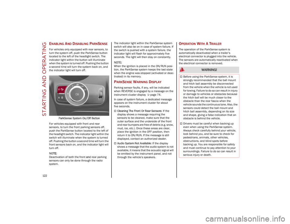
ENABLING AND DISABLING PARKSENSE
For vehicles only equipped with rear sensors, to
turn the system off, push the ParkSense button
located to the left of the headlight switch. The
indicator light within the button will illuminate
when the system is turned off. Pushing the button
a second time will turn the system back on, and
the indicator light will turn off.ParkSense System On/Off Button
For vehicles equipped with front and rear
sensors, to turn the front parking sensors off,
push the ParkSense button located to the left of
the headlight switch. The indicator light within the
switch will illuminate when the system is turned
off. Pushing the button a second time will turn the
front sensors back on, and the indicator light will
turn off.
NOTE:
Deactivation of both the front and rear parking
sensors can only be done through the radio
system. The indicator light within the ParkSense system
switch will also be on in case of system failure. If
the switch is pushed with a system failure, the
indicator light will flash for approximately five
seconds. The light will then stay on constantly.
NOTE:
When the ignition is placed in the ON/RUN posi
-
tion, the ParkSense system keeps the last state
when the engine was stopped (activated or deac -
tivated) in its memory.
PARKSENSE WARNING DISPLAY
Parking sensor faults, if any, will be indicated
when REVERSE is engaged by a message on the
instrument cluster display
Ú
page 74.
In case of system failure, a dedicated message
appears on the instrument cluster for about
five seconds.
Cleaning The Front Or Rear Sensors : If the
display shows a message requiring the
sensors to be cleaned, make sure that the
outer surface and the underside of the front
and rear bumpers are free of debris (e.g. snow,
mud, ice, etc.). Once these areas are clear,
place the ignition in the OFF position, then
return it to ON/RUN. If the message is still
displayed, contact an authorized dealer.
Audio System Not Available : If the display
shows a message that the audio system is not
available, it means that the acoustic signal will
be emitted by the instrument panel, and not
through the vehicle’s speakers.
OPERATION WITH A TRAILER
The operation of the ParkSense system is
automatically deactivated when a trailer’s
electrical connector is plugged into the vehicle.
The sensors are automatically reactivated when
the electrical connector is removed.
WARNING!
Before using the ParkSense system, it is
strongly recommended that the ball mount
and hitch ball assembly be disconnected
from the vehicle when the vehicle is not used
for towing. Failure to do so can result in injury
or damage to vehicles or obstacles because
the hitch ball will be much closer to the
obstacle than the rear fascia when the
vehicle sounds the continuous tone. Also, the
sensors could detect the ball mount and
hitch ball assembly, depending on its size
and shape, giving a false indication that an
obstacle is behind the vehicle.
Drivers must be careful when backing up
even when using the ParkSense system.
Always check carefully behind your vehicle,
look behind you, and be sure to check for
pedestrians, animals, other vehicles,
obstructions, and blind spots before
backing up. You are responsible for safety
and must continue to pay attention to your
surroundings. Failure to do so can result in
serious injury or death.
23_GU_OM_EN_USC_t.book Page 122
Page 186 of 268
IN CASE OF EMERGENCY
184
To Use SOS Emergency Call
Push and hold the SOS Emergency Call button for
a few seconds. The LED, located next to the SOS
button, will blink once and then stay on indicating
a call has been placed.
NOTE:
If the SOS Emergency Call button is accidentally
pushed, there is a 10 second delay before the call
is placed. The system will issue a verbal alert that
a call is about to be made. To cancel the call
connection, push the SOS Emergency Call button
again.
Once a connection between the vehicle and an
emergency service operator is made, the SOS
Emergency Call system will transmit the following
important vehicle information to the operator:
Indication that the occupant placed an
SOS Emergency Call.
The Vehicle Identification Number (VIN).
The last known GPS coordinates of the vehicle.
You will then be able to speak with the emergency
service operator to determine if additional help is
needed.
The SOS Emergency Call has priority over other
audio sources, which will be muted. If you have a
phone connected via Bluetooth®, it is discon -
nected and reconnected at the end of the SOS
Emergency Call. Voice prompts will guide you
during the SOS Emergency Call. If a connection is
made between an emergency service operator
and your vehicle, emergency service operators
may record conversations and sounds within your vehicle once a connection is made, and by using
the service you consent to having this information
shared.
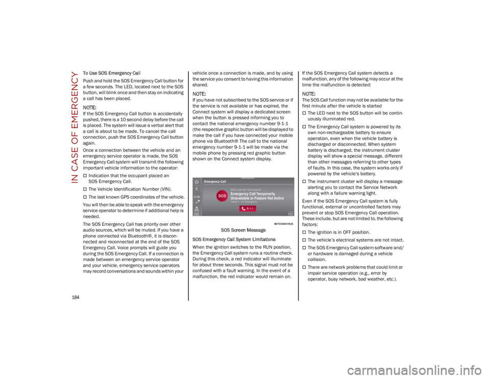
NOTE:
If you have not subscribed to the SOS service or if
the service is not available or has expired, the
Connect system will display a dedicated screen
when the button is pressed informing you to
contact the national emergency number 9-1-1
(the respective graphic button will be displayed to
make the call if you have connected your mobile
phone via Bluetooth® The call to the national
emergency number 9-1-1 will be made via the
mobile phone by pressing red graphic button
shown on the Connect system display.
SOS Screen Message
SOS Emergency Call System Limitations
When the ignition switches to the RUN position,
the Emergency Call system runs a routine check.
During this check, a red indicator will illuminate
for about three seconds. This signal must not be
confused with a fault warning. In the event of a
malfunction, the red indicator would remain on. If the SOS Emergency Call system detects a
malfunction, any of the following may occur at the
time the malfunction is detected:
NOTE:
The SOS Call function may not be available for the
first minute after the vehicle is started
The LED next to the SOS button will be contin
-
uously illuminated red.
The Emergency Call system is powered by its
own non-rechargeable battery to ensure
operation, even when the vehicle battery is
discharged or disconnected. When system
battery is discharged, the instrument cluster
display will show a special message, different
than other messages referring to other types
of faults. In this case, the system works only if
powered by the vehicle’s battery.
The instrument cluster will display a message
alerting you to contact the Service Network
along with a failure warning light.
Even if the SOS Emergency Call system is fully
functional, external or uncontrolled factors may
prevent or stop SOS Emergency Call operation.
These include, but are not limited to, the following
factors:
The ignition is in OFF position.
The vehicle’s electrical systems are not intact.
The SOS Emergency Call system software and/
or hardware is damaged during a vehicle
collision.
There are network problems that could limit or
impair service operation (e.g., error by
operator, busy network, bad weather, etc.).
23_GU_OM_EN_USC_t.book Page 184
Page 190 of 268
IN CASE OF EMERGENCY
188
14. Raise the vehicle by turning the jack screwclockwise, using the swivel wrench. Raise the
vehicle only until the tire just clears the
surface and enough clearance is obtained to
install the compact spare tire. Minimum tire
lift provides maximum stability.
15. Remove the five wheel bolts and take the wheel off.
16. Make sure the contact surfaces between compact spare tire and hub are clean so that
the fastening bolts will not come loose.
17. Fit the compact spare tire by inserting the first wheel bolt for two threads into the hole
closest to the valve.
18. Take the wheel wrench and tighten the wheel bolts.
19. Inflate the compact spare tire by removing the cap from its inflation valve and screwing
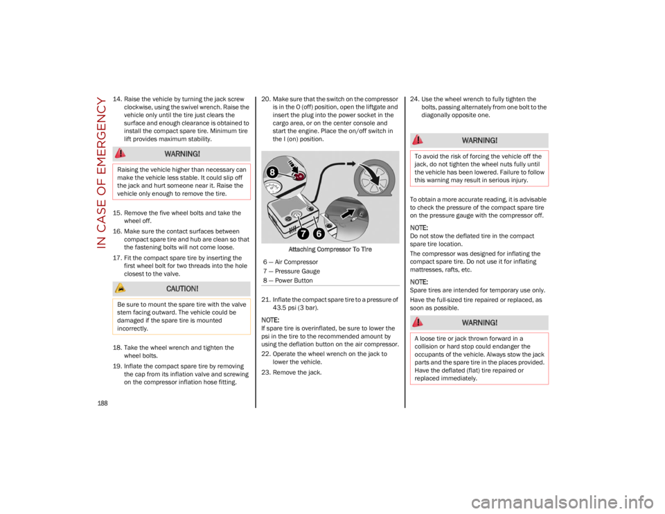
on the compressor inflation hose fitting. 20. Make sure that the switch on the compressor
is in the O (off) position, open the liftgate and
insert the plug into the power socket in the
cargo area, or on the center console and
start the engine. Place the on/off switch in
the I (on) position.
Attaching Compressor To Tire
21. Inflate the compact spare tire to a pressure of 43.5 psi (3 bar).
NOTE:
If spare tire is overinflated, be sure to lower the
psi in the tire to the recommended amount by
using the deflation button on the air compressor.
22. Operate the wheel wrench on the jack to lower the vehicle.
23. Remove the jack. 24. Use the wheel wrench to fully tighten the
bolts, passing alternately from one bolt to the
diagonally opposite one.
To obtain a more accurate reading, it is advisable
to check the pressure of the compact spare tire
on the pressure gauge with the compressor off.
NOTE:
Do not stow the deflated tire in the compact
spare tire location.
The compressor was designed for inflating the
compact spare tire. Do not use it for inflating
mattresses, rafts, etc.
NOTE:
Spare tires are intended for temporary use only.
Have the full-sized tire repaired or replaced, as
soon as possible.
WARNING!
Raising the vehicle higher than necessary can
make the vehicle less stable. It could slip off
the jack and hurt someone near it. Raise the
vehicle only enough to remove the tire.
CAUTION!
Be sure to mount the spare tire with the valve
stem facing outward. The vehicle could be
damaged if the spare tire is mounted
incorrectly.
6 — Air Compressor
7 — Pressure Gauge
8 — Power Button
WARNING!
To avoid the risk of forcing the vehicle off the
jack, do not tighten the wheel nuts fully until
the vehicle has been lowered. Failure to follow
this warning may result in serious injury.
WARNING!
A loose tire or jack thrown forward in a
collision or hard stop could endanger the
occupants of the vehicle. Always stow the jack
parts and the spare tire in the places provided.
Have the deflated (flat) tire repaired or
replaced immediately.
23_GU_OM_EN_USC_t.book Page 188
Page 211 of 268
209
3. Disconnect the black cable terminal of the battery charger and then the red cable
terminal.
4. Refit the protective cover of the positive terminal of the battery and the access cover
to the battery compartment.
NOTE:
If a "quick-type" battery charger is used with the
battery fitted on the vehicle, before connecting it
disconnect both cables of the battery itself. Do
not use a "quick-type" battery charger to provide
the starting voltage.
VEHICLE MAINTENANCE
The following pages contain instructions on the
required maintenance from the technical
personnel who designed the vehicle.
In addition to these specific maintenance
instructions specified for routine scheduled
servicing, there are other components which may
require periodic maintenance or replacement
over the vehicle’s life cycle.
ENGINE OIL
Engine Oil Level Check
To ensure correct engine lubrication, the oil must
always be kept at the prescribed level
Ú
page 204.
Check the oil level at regular intervals, for
example every 1,864 miles (3,000 km).
It must be checked about five minutes after
stopping the engine.
Full operating temperature must be reached. The
vehicle must also be parked on as level a surface
as possible. The engine oil level can be checked using the
Information and Entertainment system. To
access the function, activate the main menu
(MENU button) and select the following options in
sequence:
1. “Vehicle Information”
2. “Engine Oil”
Ensure that the oil level is within the interval on
the dipstick between the minimum and maximum
limits (Quadrifoglio only).
Changing The Engine Oil
For the correct servicing intervals
Ú
page 200.
Choice Of Engine Oil Type
To ensure optimal performance and maximum
protection in all operating conditions, it is advised
to use certified engine oils
Ú
page 252.
Additives For Engine Oil
It is strongly recommended not to use additives
(other than leak detection dyes) with the engine
oil.
The engine oil is a product designed especially for
the vehicle, and its performance may be deteri -
orated through the use of further additives.
Disposal Of Used Engine Oil And Filters
For the disposal of the engine oil and filters,
contact the appropriate body to determine local
regulations.
NOTE:
Incorrectly disposed used engine oil may seri -
ously harm the environment.
ENGINE OIL FILTER
Replacing the Engine Oil Filter
The engine oil filter must be replaced each time
the engine oil is changed. It is advised to replace
it with a genuine spare part, specifically designed
for this vehicle.
ENGINE AIR CLEANER FILTER
Replacing the Engine Air Cleaner Filter
For the correct servicing intervals
Ú
page 200. It
is advised to replace the engine air cleaner filter
with a genuine spare part, specifically designed
for this vehicle.
AIR CONDITIONING SYSTEM
M
AINTENANCE
To ensure the best possible performance, the air
conditioning system must be checked and
undergo maintenance at an authorized dealer at
the beginning of the summer.
CAUTION!
Do not use chemicals to clean the air
conditioning system, since the internal
components may be damaged. This kind of
damage is not covered by warranty.
23_GU_OM_EN_USC_t.book Page 209
Page 242 of 268
SERVICING AND MAINTENANCE
240
Dry the less visible parts (e.g. door frames, hood,
headlight frames, etc.) with special care, as water
may stagnate more easily in these areas. Do not
wash the vehicle after it has been left in the sun
or with the hood hot: this may alter the shine of
the paintwork.
NOTE:
Avoid parking under trees; the resin dropped by
trees makes the paintwork go opaque and
increases the possibility of corrosion.
Exterior plastic parts must be cleaned in the
same way as the rest of the vehicle.
If washing the vehicle in a service that moves the
vehicle, for vehicles with automatic
transmissions, proceed with the following
directions:
Ensure that the vehicle is on a flat surface.
Disable the automatic engagement of the
parking brake
Ú
page 89.
With the vehicle stationary, the gear in
NEUTRAL (N) and the brake pedal pressed,
push the START button.
NOTE:
The vehicle will remain in NEUTRAL (N) for
15 minutes before PARK (P) will be engaged
automatically.Windows
Use specific detergents and clean cloths to
prevent scratching or altering the transparency.
Front Headlights
Use a soft cloth soaked in water and detergent for
washing vehicles.
NOTE:
Never use aromatic substances (e.g. gasoline)
or ketones (e.g. acetone) for cleaning the
plastic lenses of the headlights.
When cleaning with a pressure washer, keep
the pressure washer at least eight inches
(20 cm) away from the headlights.
Engine Compartment
At the end of every Winter, wash the engine
compartment thoroughly, taking care not to aim
the jet of water directly at the electronic control
units or at the windshield wiper motors. Have this
operation performed at a specialized workshop
Ú
page 208.
NOTE:
The washing should take place with the engine
cold and the ignition device in the STOP position.
After the washing operation, make sure that the
various protections (e.g. rubber caps and guards)
have not been removed or damaged.
INTERIORS
Periodically check the cleanliness of the interior,
beneath the mats, which could cause oxidation of
the sheet metal.
SEATS AND FABRIC PARTS
Remove dust with a soft brush or a vacuum
cleaner. It is advised to use a moist brush on
velvet upholstery. Rub the seats with a sponge
moistened with a solution of water and neutral
detergent.
Cleaning heat press images on seats —
if equipped:
Due to the color, opacity and wear-resistant
protection with which the heat press images on
some seats are made, they may be subject to
temporary scratching if they are touched by finger
nails, keys, or other hard objects. In such cases,
the visible signs do not impair the profiled
images, and can easily be removed by wiping the
affected area with a microfiber cloth moistened
with water (not dry) to restore the seat to its
original condition. The microfiber cloth must not
have been previously soaked in other substances
or detergents.
CAUTION!
Wipe the rear window inside gently with a
cloth following the direction of the filaments to
avoid damaging the heating device.
23_GU_OM_EN_USC_t.book Page 240