fuel cap ALFA ROMEO STELVIO 2023 Owners Manual
[x] Cancel search | Manufacturer: ALFA ROMEO, Model Year: 2023, Model line: STELVIO, Model: ALFA ROMEO STELVIO 2023Pages: 268, PDF Size: 10.36 MB
Page 13 of 268
11
LANE DEPARTURE WARNING (LDW)
SYSTEM ................................................. 123
Lane Departure Warning
Operation ..............................................123 Turning Lane Departure Warning On
Or Off .................................................... 124 Lane Departure Warning Message.....124
Changing Lane Departure Warning
Status ................................................... 125
LANE KEEPING ASSIST (LKA) SYSTEM —
IF EQUIPPED .......................................... 125
Turning Lane Keeping
Assist On Or Off ....................................126 Lane Keeping Assist Warning
Message ...............................................126
REAR BACK UP CAMERA / DYNAMIC
GRIDLINES ............................................ 128
REFUELING THE VEHICLE ..................... 129
Refueling Capacity ............................... 129
Refueling Procedure ...........................130
VEHICLE LOADING ................................ 132
Certification Label................................ 132
TRAILER TOWING................................... 133
Common Towing Definitions ...............133
Trailer Hitch Classification .................. 134
Trailer Towing Weights
(Maximum Trailer Weight Ratings) .....134 Trailer And Tongue Weight ................. 135
Towing Requirements..........................135
Towing Tips ......................................... 137
Installing The Receiver ....................... 137
Connecting The Electrical System...... 138
Removing The Receiver ...................... 138
SUGGESTIONS FOR DRIVING................ 138
Saving Fuel .......................................... 138
Driving Style......................................... 139
Conditions Of Use................................ 139
Performance — Quadrifoglio ............... 139
SAFETY
ACTIVE SAFETY SYSTEMS ..................... 140
Anti-Lock Brake System (ABS) ........... 140
Active Torque Vectoring (ATV)
System — If Equipped ......................... 140 Dynamic Steering Torque (DST)
System ................................................. 141 Drive Train Control (DTC) System....... 141
Electronic Stability Control (ESC)
System ................................................. 141 Hill Descent Control (HDC) System —
If Equipped .......................................... 142 Hill Start Assist (HSA) System ............ 143
Panic Brake Assist (PBA) System ....... 143
Traction Control System (TCS)............ 144
AUXILIARY DRIVING SYSTEMS .............. 144
Blind Spot Monitoring (BSM) System —
If Equipped ........................................... 144 Active Blind Spot Assist (ABSA)
System — If Equipped ......................... 146 Driver Attention Assist (DAA) System —
If Equipped ........................................... 149 Forward Collision Warning
Plus (FCW+) System —
If Equipped .......................................... 151 Tire Pressure Monitoring
System (TPMS) .................................... 155
OCCUPANT RESTRAINT SYSTEMS ....... 157
Occupant Restraint Systems
Features .............................................. 157 Important Safety Precautions............. 157
Seat Belt Systems .............................. 158
Supplemental Restraint
Systems (SRS) ..................................... 162 Child Restraints ................................... 170
SAFETY TIPS .......................................... 180
Transporting Passengers .................... 180
Transporting Pets ............................... 180
Connected Vehicles ............................. 180
Safety Checks You Should Make
Inside The Vehicle .............................. 180 Periodic Safety Checks You
Should Make Outside The Vehicle ..... 182 Exhaust Gas ......................................... 182
Carbon Monoxide Warnings................ 182
23_GU_OM_EN_USC_t.book Page 11
Page 15 of 268

13
TIRES ..................................................... 224
Tire Safety Information ....................... 224
Tires — General Information................ 230
Spare Tires — If Equipped ...................234
Wheel And Wheel Trim Care ..............235
Tire Types ............................................. 236
Tire Chains and Traction Devices .......236
Tire Rotation Recommendations ........237
DEPARTMENT OF TRANSPORTATION
UNIFORM TIRE QUALITY GRADES ....... 238
Treadwear ............................................ 238
Traction Grades ...................................238
Temperature Grades ...........................238
STORING THE VEHICLE ........................ 238
BODYWORK ........................................... 239
Protection Against Atmospheric
Agents ................................................... 239 Corrosion Warranty .............................. 239
Preserving The Bodywork ....................239
INTERIORS ............................................. 240
Seats And Fabric Parts ........................ 240
Leather Seats....................................... 241
Plastic And Coated Parts .....................241
Alcantara Parts — If Equipped.............241
Genuine Leather Parts ........................ 241
Carbon Fiber Parts ............................... 241
TECHNICAL SPECIFICATIONS
VEHICLE IDENTIFICATION
NUMBER (VIN) ....................................... 242
Vehicle Identification Number (VIN)
Plate ..................................................... 242
ENGINE .................................................. 242 POWER SUPPLY ..................................... 243
TRANSMISSION ..................................... 244
BRAKES .................................................. 244SUSPENSION ......................................... 245
STEERING .............................................. 245
DIMENSIONS ......................................... 246
Luggage Compartment Volume ......... 247
WEIGHTS ................................................ 248FUEL REQUIREMENTS........................... 249
Reformulated Gasoline ...................... 249
Gasoline/Oxygenate Blends ............... 249
CNG And LP Fuel System
Modifications ....................................... 250 MMT In Gasoline ................................. 250
Materials Added To Fuel ..................... 250
Fuel System Cautions ......................... 250
FLUID CAPACITIES ................................ 251
ENGINE FLUIDS AND LUBRICANTS ...... 252
CHASSIS FLUIDS AND LUBRICANTS ..... 253 PERFORMANCE ..................................... 254
CUSTOMER ASSISTANCE
SUGGESTIONS FOR OBTAINING
SERVICE FOR YOUR VEHICLE .............. 255
Prepare For The Appointment ............ 255
Prepare A List ...................................... 255
Be Reasonable With Requests ........... 255
IF YOU NEED ASSISTANCE .................... 255
Roadside Assistance ........................... 255
Alfa Romeo Customer Center ............. 256
Alfa Romeo Customer
Care (Canada) ...................................... 256 Customer Assistance For
The Hearing Or
Speech Impaired (TDD/TTY) ............... 256 Service Contract ................................. 257
WARRANTY INFORMATION ................... 257REPORTING SAFETY DEFECTS .............. 258
In The 50 United States And
Washington, D.C. ................................. 258 In Canada ............................................. 258
PUBLICATION ORDER FORMS .............. 258
GENERAL INFORMATION....................... 259
23_GU_OM_EN_USC_t.book Page 13
Page 19 of 268

17
Generic Indication
Ú
page 82
Highway Assist System (HAS)/Traffic Jam Assist (TJA) System Failure
Ú
page 82
Keyless System Failure
Ú
page 82
Lane Departure Warning (LDW) System Failure
Ú
page 82
Loose Fuel Filler Cap
Ú
page 82
Low Coolant Level
Ú
page 82
Park Sensors System Failure
Ú
page 82
Rain Sensor Failure
Ú
page 82
Stop/Start System Failure
Ú
page 83
Amber Symbols
Speed Limiter System Failure
Ú
page 83
Service Adaptive Cruise Control (ACC) System
Ú
page 82
Soft Suspension Calibration Insertion
Ú
page 83
Shock Absorbers Failure
Ú
page 83
Temporary All Wheel Drive Failure
Ú
page 83
Wear On Brake Pads
Ú
page 83
Windshield Wiper Failure
Ú
page 83
Windshield Washer Liquid Level
Ú
page 82
Amber Symbols
23_GU_OM_EN_USC_t.book Page 17
Page 84 of 268
GETTING TO KNOW YOUR INSTRUMENT PANEL
82
Engine Oil Level Sensor Failure
The telltale will illuminate in the event of
engine oil level sensor failure.
Contact an authorized dealer as soon as
possible.
Engine Oil Pressure Sensor Failure
The telltale will illuminate in the event of
engine oil pressure sensor failure.
Contact an authorized dealer as soon as
possible.
Fuel Cut-Off System Failure
The telltale will illuminate in the event of
fuel cut-off system failure.
Contact an authorized dealer as soon as
possible.
Fuel Cut-Off Indicator Light
The telltale will illuminate after an
accident has occurred and the system
has shut the fuel off.
For reactivating the fuel cut-off system
Ú
page 157. If it is not possible to restore the fuel
supply, contact an authorized dealer.
Fuel Level Sensor Failure
The telltale will illuminate in the event of
fuel level sensor failure.
Contact an authorized dealer as soon as
possible.
Generic Indication
Signals information and failures.
The accompanying messages describe the
failure.
Highway Assist System (HAS)/Traffic Jam
Assist (TJA) System Failure
The symbol lights up in case of HAS or
TJA system failure.
Contact an Alfa Romeo Dealership as soon as
possible to have the failure eliminated.
Keyless System Failure
The telltale will illuminate in the event of
keyless system failure.
Contact an authorized dealer as soon as
possible.
Lane Departure Warning (LDW) System
Failure — If Equipped
The telltale will illuminate in the event of
a fault in the Lane Departure Warning
system.
Contact an authorized dealer as soon as
possible.
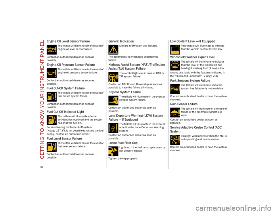
Loose Fuel Filler Cap
Lights up if the fuel tank cap is open or
not properly closed.
Tighten the cap properly.
Low Coolant Level — If Equipped
This telltale will illuminate to indicate
that the vehicle coolant level is low.
Windshield Washer Liquid Level
The telltale will illuminate to indicate
that the level of the windshield and
headlight washing fluid (if any) is low.
Always use liquid with the features indicated in
the “Fluids And Lubricants”
Ú
page 206.
Park Sensors System Failure
The telltale will illuminate when the
system has failed or is not available.
Contact an authorized dealer to have the system
checked.
Rain Sensor Failure
The telltale will illuminate in the case of
failure of the automatic windshield
wiper.
Contact an authorized dealer as soon as
possible.
Service Adaptive Cruise Control (ACC)
System
This light will illuminate when the ACC is
not operating and needs service.
Contact an authorized dealer to have the system
checked.
23_GU_OM_EN_USC_t.book Page 82
Page 131 of 268
129
When enabled in the radio settings, active
guidelines are overlaid on the image to illustrate
the width of the vehicle and its projected back up
path based on the steering wheel position. A
dashed center line overlay indicates the center of
the vehicle to assist in rear parking maneuvers or
trailer hitch alignment. Different colored zones
indicate the distance to the rear of the vehicle.
The following table shows the approximate
distances for each zone:
Messages On The Display
If the liftgate is opened, the camera will not detect
any obstacle behind the vehicle. The display will
show a dedicated warning message.
Make sure the liftgate is closed by pushing next to
the lock until it clicks.Important Notes
Ice, snow or mud on the surface of the camera
may reduce its sensitivity. It is important to
keep the camera surface clean, and free from
debris.
When parking, be aware of obstacles that may
be above or below the camera range.
REFUELING THE VEHICLE
Before refueling, make sure that the fuel type is
correct
Ú
page 249.
Also, stop the engine before refueling.
NOTE:
An inefficient catalytic converter leads to
harmful exhaust emissions, thus contributing to
air pollution.
REFUELING CAPACITY
To ensure that you fill the tank completely, top off
twice after the first click of the fuel nozzle.
Further top-off could cause faults in the fuel
feeding system.
AreaDistance From The
Rear Of The Vehicle
Red 0–11.8 inches
(0–30 cm)
Yellow 11.8 inches to 3.3 feet
(30 cm–1 m)
Green 3.3 feet or more
(1 m or more)
WARNING!
Drivers must be careful when backing up even
when using the Rear Back Up Camera. Always
check carefully behind your vehicle, and be
sure to check for pedestrians, animals, other
vehicles, obstructions, or blind spots before
backing up. You are responsible for the safety
of your surroundings and must continue to pay
attention while backing up. Failure to do so
can result in serious injury or death.
CAUTION!
To avoid vehicle damage, Rear Back Up
Camera should only be used as a parking aid.
The Rear Back Up Camera is unable to view
every obstacle or object in your drive path.
To avoid vehicle damage, the vehicle must
be driven slowly when using the Rear Back
Up Camera to be able to stop in time when an
obstacle is seen. It is recommended that the
driver look frequently over his/her shoulder
when using the Rear Back Up Camera.
CAUTION!
Never introduce leaded fuel to the tank,
even in small amounts in an emergency, as
this would damage the catalytic converter
beyond repair.
23_GU_OM_EN_USC_t.book Page 129
Page 132 of 268
STARTING AND OPERATING
130
REFUELING PROCEDURE
The fuel filler door is unlocked when the central
door locking system is unlocked. It is automat-
ically locked when the central locking system is
applied.
Opening The Fuel Filler Door
To refuel proceed as follows:
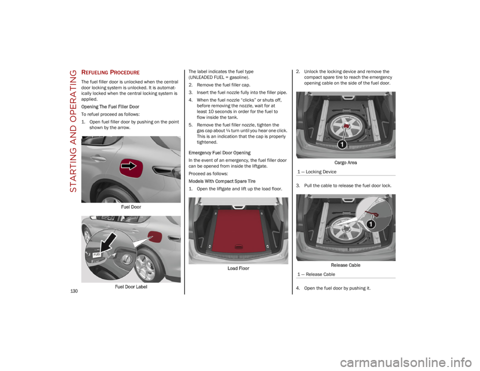
1. Open fuel filler door by pushing on the point shown by the arrow.
Fuel Door
Fuel Door Label The label indicates the fuel type
(UNLEADED FUEL = gasoline).
2. Remove the fuel filler cap.
3. Insert the fuel nozzle fully into the filler pipe.
4. When the fuel nozzle “clicks” or shuts off,
before removing the nozzle, wait for at
least 10 seconds in order for the fuel to
flow inside the tank.
5. Remove the fuel filler nozzle, tighten the gas cap about ¼ turn until you hear one click.
This is an indication that the cap is properly
tightened.
Emergency Fuel Door Opening
In the event of an emergency, the fuel filler door
can be opened from inside the liftgate.
Proceed as follows:
Models With Compact Spare Tire
1. Open the liftgate and lift up the load floor.
Load Floor 2. Unlock the locking device and remove the
compact spare tire to reach the emergency
opening cable on the side of the fuel door.
Cargo Area
3. Pull the cable to release the fuel door lock.
Release Cable
4. Open the fuel door by pushing it.
1 — Locking Device
1 — Release Cable
23_GU_OM_EN_USC_t.book Page 130
Page 134 of 268
STARTING AND OPERATING
132
VEHICLE LOADING
CERTIFICATION LABEL
As required by National Highway Traffic Safety
Administration regulations, your vehicle has a
certification label affixed to the driver's side door
or pillar.
This label contains the month and year of
manufacture, Gross Vehicle Weight Rating
(GVWR), Gross Axle Weight Rating (GAWR) front
and rear, and Vehicle Identification Number
(VIN). A Month-Day-Hour (MDH) number is
included on this label and indicates the Month,
Day and Hour of manufacture. The bar code that
appears on the bottom of the label is your VIN.
Gross Vehicle Weight Rating (GVWR)
The GVWR is the total permissible weight of your
vehicle including driver, passengers, vehicle,
options and cargo. The label also specifies
maximum capacities of front and rear axle
systems (GAWR). Total load must be limited so
GVWR and front and rear GAWR are not
exceeded.
Payload
The payload of a vehicle is defined as the
allowable load weight a truck can carry, including
the weight of the driver, all passengers, options
and cargo.
Gross Axle Weight Rating (GAWR)
The GAWR is the maximum permissible load on
the front and rear axles. The load must be
distributed in the cargo area so that the GAWR of
each axle is not exceeded.
Each axle GAWR is determined by the
components in the system with the lowest load
carrying capacity (axle, springs, tires or wheels).
Heavier axles or suspension components
sometimes specified by purchasers for increased
durability do not necessarily increase the
vehicle's GVWR.
Tire Size
The tire size on the Vehicle Certification Label
represents the actual tire size on your vehicle.
Replacement tires must be equal to the load
capacity of this tire size.
Rim Size
This is the rim size that is appropriate for the
tire size listed.
Inflation Pressure
This is the cold tire inflation pressure for your
vehicle for all loading conditions up to full GAWR.
Curb Weight
The curb weight of a vehicle is defined as the total
weight of the vehicle with all fluids, including
vehicle fuel, at full capacity conditions, and with
no occupants or cargo loaded into the vehicle.
The front and rear curb weight values are
determined by weighing your vehicle on a
commercial scale before any occupants or
cargo are added.
Loading
The actual total weight and the weight of the front
and rear of your vehicle at the ground can best be
determined by weighing it when it is loaded and
ready for operation.
The entire vehicle should first be weighed on a
commercial scale to ensure that the GVWR has
not been exceeded. The weight on the front and
rear of the vehicle should then be determined
separately to be sure that the load is properly
distributed over the front and rear axle. Weighing
the vehicle may show that the GAWR of either the
front or rear axles has been exceeded but the
total load is within the specified GVWR. If so,
weight must be shifted from front to rear or rear
to front as appropriate until the specified weight
limitations are met. Store the heavier items down
low and be sure that the weight is distributed
equally. Stow all loose items securely before
driving.
Improper weight distributions can have an
adverse effect on the way your vehicle steers and
handles and the way the brakes operate.
WARNING!
Do not load your vehicle any heavier than the
GVWR or the maximum front and rear GAWR. If
you do, parts on your vehicle can break, or it
can change the way your vehicle handles. This
could cause you to lose control. Overloading
can shorten the life of your vehicle.
23_GU_OM_EN_USC_t.book Page 132
Page 141 of 268

139
DRIVING STYLE
Starting
Do not warm up the engine at low or high revs
when the vehicle is stationary; this causes the
engine to warm up more slowly, thereby
increasing fuel consumption and emissions. It is
therefore advisable to drive off immediately,
slowly, avoiding high speeds: by doing this the
engine will warm up more quickly.
Unnecessary Actions
Avoid revving up when starting at traffic lights or
before stopping the engine. This action is
unnecessary and causes increased fuel
consumption and pollution.
Gear Selection
Use a high gear when traffic and road conditions
allow it. Using a low gear for faster acceleration
will increase fuel consumption. Improper use of a
high gear increases consumption, emissions and
engine wear.
Maximum Speed
Fuel consumption considerably increases as
speed increases. Maintain a constant speed,
avoiding unnecessary braking and acceleration,
which cost in terms of both fuel consumption and
emissions.
Acceleration
Accelerating violently severely affects
consumption and emissions: acceleration should
be gradual and should not exceed the maximum
torque.
CONDITIONS OF USE
Cold Starting
Short trips and frequent cold starts will not allow
the engine to reach optimum operating
temperature. This results in a significant increase
in consumption levels (from +15 to +30% in
city driving) and emissions.
Traffic And Road Conditions
High fuel consumption is caused by heavy traffic,
for instance when traveling in traffic with frequent
use of low gears or in cities with many traffic
lights. Winding mountain roads and rough road
surfaces also adversely affect consumption.
Stops In Traffic
During prolonged stops (e.g. railway crossings),
turn off the engine.
PERFORMANCE — QUADRIFOGLIO
This vehicle is equipped with an engine capable
of delivering exceptionally fast acceleration and
speed:
Peak power: 505 HP at 6,500 RPM.
Peak torque: 443 ft-lb at 2,500–5,000 RPM.
Top speed: 176 mph (283 km/h).
Acceleration from 0 to 60 mph (0 to 100 km/h):
3.6 seconds.
For safe driving, it is essential, particularly during
the first days of use, to get to know the car by
driving carefully and gradually discovering its
performance.
Driving On Race Tracks
Before driving on a track using a racing style, it is
necessary to:
Attend a race track driving course.
Check the liquid levels in the engine
compartment
Ú
page 199.
Have the car inspected at an authorized
dealer.
Remember that the car was not designed to be
driven exclusively on the race track and that this
use increases stress and component wear.
NOTE:
Quadrifoglio front brakes are equipped with
Non-Asbestos Organic (NAO) type pads. These
pads are NOT suitable for high thermal loads
(for example track use).
23_GU_OM_EN_USC_t.book Page 139
Page 143 of 268
141
(Continued)
DYNAMIC STEERING TORQUE (DST)
S
YSTEM
DST uses the integration of the Electronic
Stability Control (ESC) system with the electric
power steering to increase the safety level of the
whole vehicle.
In critical situations (e.g. braking on surfaces with
different grip conditions), the ESC system
influences the steering through the DST function
to implement an additional torque contribution
on the steering wheel in order to suggest the
most correct maneuver to the driver.
The coordinated action of the brakes and steering
increases the safety and control of the vehicle.
NOTE:
The DST feature is only meant to help the driver
realize the correct course of action through small
torques on the steering wheel, which means the
effectiveness of the DST feature is highly depen -
dent on the driver’s sensitivity and overall reac -
tion to the applied torque. It is very important to
realize that this feature will not steer the vehicle,
meaning the driver is still responsible for steering
the vehicle.
DRIVE TRAIN CONTROL (DTC) SYSTEM
Some models of this vehicle are equipped with an
All-Wheel Drive (AWD) system, which offers an
optimal drive for countless driving conditions and
road surfaces. The system reduces tire slipping to
a minimum, automatically redistributing the
torque to the front and rear wheels as needed. To maximize fuel savings, the vehicle with AWD
automatically passes to Rear-Wheel Drive (RWD)
when the road and environmental conditions are
such that they wouldn't cause the tires to slip.
When the road and environmental conditions
require better traction, the vehicle automatically
switches to AWD mode.
NOTE:
There may be a brief delay in shifting to
AWD mode after a tire slipping event occurs.
If the system failure symbol switches on, after
starting the engine or while driving, it means
that the AWD system is not working properly. If
the warning message activates frequently, it is
recommended to carry out the maintenance
operations.
ELECTRONIC STABILITY CONTROL (ESC)
S
YSTEM
The ESC system improves the directional control
and stability of the vehicle in various driving
conditions.
The ESC system corrects the vehicle’s understeer
and oversteer, distributing the brake force on the
appropriate wheels. The torque supplied by the
engine can also be reduced in order to maintain
control of the vehicle.
The ESC system uses sensors installed on the
vehicle to determine the path that the driver
intends to follow and compares it with the
vehicle’s effective path. When the real path
deviates from the desired path, the ESC system
intervenes to counter the vehicle’s oversteer or
understeer.
Oversteer occurs when the vehicle is turning
more than it should according to the angle of
the steering wheel.
Understeer occurs when the vehicle is turning
less than it should according to the angle of the
steering wheel.
System Intervention
The intervention of the system is indicated by the
flashing of the ESC Warning Light on the
instrument panel, to inform the driver that the
vehicle stability and grip are critical.
WARNING!
Electronic Stability Control (ESC) cannot
prevent the natural laws of physics from
acting on the vehicle, nor can it increase the
traction afforded by prevailing road
conditions. ESC cannot prevent accidents,
including those resulting from excessive
speed in turns, driving on very slippery
surfaces, or hydroplaning. ESC also cannot
prevent accidents resulting from loss of
vehicle control due to inappropriate driver
input for the conditions. Only a safe,
attentive, and skillful driver can prevent
accidents. The capabilities of an ESC
equipped vehicle must never be exploited in
a reckless or dangerous manner which could
jeopardize the user’s safety or the safety of
others.
23_GU_OM_EN_USC_t.book Page 141
Page 232 of 268
SERVICING AND MAINTENANCE
230
TIRES — GENERAL INFORMATION
Tire Pressure
Proper tire inflation pressure is essential to the
safe and satisfactory operation of your vehicle.
Four primary areas are affected by improper
tire pressure:
Safety
Fuel Economy
Tread Wear
Ride Comfort and Vehicle Stability
Safety Both underinflation and overinflation affect the
stability of the vehicle and can produce a feeling
of sluggish response or over responsiveness in
the steering.
NOTE:
Unequal tire pressures from side to side may
cause erratic and unpredictable steering
response.
Unequal tire pressure from side to side may
cause the vehicle to drift left or right.
Fuel Economy
Underinflated tires will increase tire rolling
resistance resulting in higher fuel consumption.
Tread Wear
Improper cold tire inflation pressures can cause
abnormal wear patterns and reduced tread life,
resulting in the need for earlier tire replacement.
Ride Comfort And Vehicle Stability
Proper tire inflation contributes to a comfortable
ride. Overinflation produces a jarring and
uncomfortable ride.
Tire Inflation Pressures
The proper cold tire inflation pressure is listed on
the driver's side B-pillar or rear edge of the
driver's side door.
At least once a month:
Check and adjust tire pressure with a good
quality pocket-type pressure gauge. Do not
make a visual judgement when determining
proper inflation. Tires may look properly
inflated even when they are underinflated.
Inspect tires for signs of tire wear or visible
damage. Inflation pressures specified on the placard are
always “cold tire inflation pressure”. Cold tire
inflation pressure is defined as the tire pressure
after the vehicle has not been driven for at least
three hours, or driven less than 1 mile (1.6 km)
after sitting for a minimum of three hours. The
cold tire inflation pressure must not exceed the
maximum inflation pressure molded into the tire
sidewall.
Check tire pressures more often if subject to a
wide range of outdoor temperatures, as tire
pressures vary with temperature changes.
Tire pressures change by approximately 1 psi
(7 kPa) per 12°F (7°C) of air temperature
change. Keep this in mind when checking tire
pressure inside a garage, especially in the Winter.
Example: If garage temperature = 68°F (20°C)
and the outside temperature = 32°F (0°C) then
the cold tire inflation pressure should be
increased by 3 psi (21 kPa), which equals 1 psi
(7 kPa) for every 12°F (7°C) for this outside
temperature condition.
Tire pressure may increase from 2 to 6 psi
(13 to 40 kPa) during operation. DO NOT reduce
this normal pressure build up or your tire
pressure will be too low.
WARNING!
Improperly inflated tires are dangerous and
can cause collisions.
Underinflation increases tire flexing and can
result in overheating and tire failure.
Overinflation reduces a tire's ability to
cushion shock. Objects on the road and
chuckholes can cause damage that result in
tire failure.
Overinflated or underinflated tires can affect
vehicle handling and can fail suddenly,
resulting in loss of vehicle control.
Unequal tire pressures can cause steering
problems. You could lose control of your
vehicle.
Unequal tire pressures from one side of the
vehicle to the other can cause the vehicle to
drift to the right or left.
Always drive with each tire inflated to the
recommended cold tire inflation pressure.
CAUTION!
After inspecting or adjusting the tire pressure,
always reinstall the valve stem cap. This will
prevent moisture and dirt from entering the
valve stem, which could damage the valve
stem.
23_GU_OM_EN_USC_t.book Page 230